ROS2 LiDAR SLAM AMR
This project develops an Autonomous Mobile Robot (AMR) for indoor logistics-style navigation using LiDAR-based SLAM and ROS2. Unlike line-following IR robots or camera-only systems sensitive to lighting, LiDAR provides real-time 360° ranging that works in the dark and supports dynamic map building.
RPLidar Raspberry Pi Nav2 — Autonomous Mobile Robot SLAM. Canonical URL: https://www.projectsatbangalore.com/SLAM/lidar-based-slam-navigation-for-mobile-robots/
Reference architecture aligned with: Salihu et al., “SLAM-Based Indoor Navigation with LiDAR and ROS2 for Autonomous Mobile Robot,” Ife Journal of Technology (2025).
Tools & Stack
Hardware Architecture
Base station PC + onboard robot linked over WiFi (ROS2 DDS). On the robot:
- Raspberry Pi 4 — high-level control,
rplidar_node, serial bridge - Arduino Nano — PID wheel velocity, encoder interrupts, PWM to motor driver
- 2D LiDAR (e.g. RPLidar A1) — 360° scans, ~6–12 m range class
- 12V DC gear motors with magnetic encoders + L298N dual H-bridge
- LiPo / 12V battery pack; common ground between logic and power domains
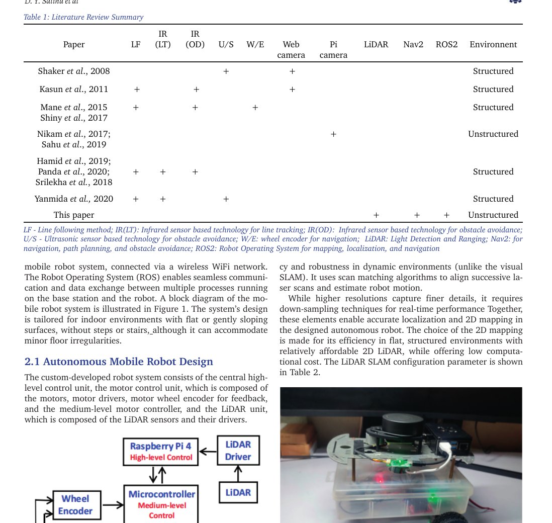
Block diagram and hardware setup (paper Figures 1–2 style).
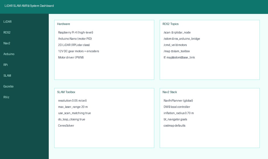
System dashboard: hardware, topics, SLAM toolbox, Nav2.
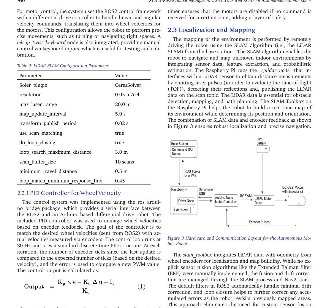
Hardware and communication layout (RPi, Arduino, LiDAR, motors).
Circuit / Wiring Overview
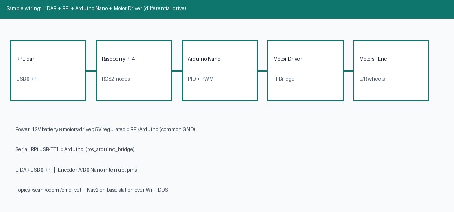
Sample signal path: LiDAR → RPi → Arduino PID → motor driver → wheels + encoders.
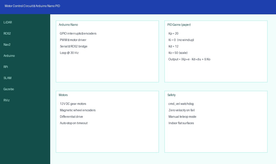
PID motor control panel — gains from reference implementation (Kp=20, Ki=0, Kd=12, Ko=50).
Typical connections
- LiDAR USB → Raspberry Pi
- Arduino Nano USB-serial → Pi (
ros_arduino_bridge) - Encoder A/B channels → Nano interrupt-capable pins
- Nano PWM + DIR → L298N IN/EN pins
- L298N OUT → left/right motors; 12V battery → driver VM; 5V logic shared GND
SLAM Toolbox Configuration (Reference)
- Solver: CeresSolver · resolution 0.05 m/cell · max laser range 20 m
- map_update_interval 5 s · transform publish period 0.02 s
- use_scan_matching true · do_loop_closing true
- loop_search_maximum_distance 3.0 m · scan_buffer_size 10
- minimum_travel_distance 0.5 m · loop_match minimum response fine 0.45
Nav2: NavfnPlanner (global), DWB local controller, default costmap inflation radius ≈ 0.70 m. Mapping can be done with teleop_twist_keyboard; goals via RViz /navigate_to_pose.

ROS2 node architecture: onboard sensor/motor nodes vs base-station slam_toolbox + Nav2.
Sample Circuit Code — Arduino PID (sketch)
Illustrative structure matching the paper’s discrete PID (loop ~30 Hz). Tune gains on your chassis.
// Arduino Nano — differential drive PID (illustrative)
// Encoder ticks → velocity error → PWM via Kp,Kd,Ko

volatile long leftTicks = 0, rightTicks = 0;
const int LEFT_A = 2, RIGHT_A = 3;   // interrupt pins
const int PWM_L = 5, PWM_R = 6;
const int DIR_L = 7, DIR_R = 8;

float Kp = 20, Kd = 12, Ki = 0, Ko = 50;
float I_L = 0, I_R = 0;
float prevVelL = 0, prevVelR = 0;
float targetL = 0, targetR = 0; // ticks per frame from ROS

void leftISR()  { leftTicks++; }
void rightISR() { rightTicks++; }

void setup() {
  pinMode(PWM_L, OUTPUT); pinMode(PWM_R, OUTPUT);
  pinMode(DIR_L, OUTPUT); pinMode(DIR_R, OUTPUT);
  attachInterrupt(digitalPinToInterrupt(LEFT_A), leftISR, RISING);
  attachInterrupt(digitalPinToInterrupt(RIGHT_A), rightISR, RISING);
  Serial.begin(115200); // ros_arduino_bridge protocol
}

void pidStep() {
  long dL = leftTicks; leftTicks = 0;
  long dR = rightTicks; rightTicks = 0;
  float eL = targetL - dL;
  float eR = targetR - dR;
  float dVelL = dL - prevVelL; prevVelL = dL;
  float dVelR = dR - prevVelR; prevVelR = dR;
  // anti-windup: only integrate if not saturated
  float outL = (Kp * eL - Kd * dVelL + I_L) / Ko;
  float outR = (Kp * eR - Kd * dVelR + I_R) / Ko;
  outL = constrain(outL, -255, 255);
  outR = constrain(outR, -255, 255);
  drive(PWM_L, DIR_L, outL);
  drive(PWM_R, DIR_R, outR);
}

void drive(int pwmPin, int dirPin, float u) {
  digitalWrite(dirPin, u >= 0 ? HIGH : LOW);
  analogWrite(pwmPin, (int)abs(u));
}

void loop() {
  // Parse cmd_vel targets from serial bridge → targetL/R
  pidStep();
  delay(33); // ~30 Hz
}
Python / ROS2 launch sketch (base station)
# illustrative launch order (shell / ROS2)
# On robot (RPi):
ros2 run rplidar_ros rplidar_node
ros2 run ros_arduino_python arduino_node   # publishes /odom, subs /cmd_vel

# On base station:
ros2 launch slam_toolbox online_async_launch.py
# drive with teleop while mapping, then:
ros2 run nav2_map_server map_saver_cli -f ~/maps/room
ros2 launch nav2_bringup bringup_launch.py map:=~/maps/room.yaml
# set 2D Nav Goal in RViz → /navigate_to_pose
Simulation & Real-World Results (Paper)
- Gazebo building model → occupancy map in RViz; goal navigation without collision
- Real room ≈ 4.8 × 3 m, robot footprint ≈ 0.3 × 0.3 m, static desks/chairs
- Successful path P → Q → R around obstacles on generated map
- Angular drift higher in narrow corridors than open space (odometry limits)
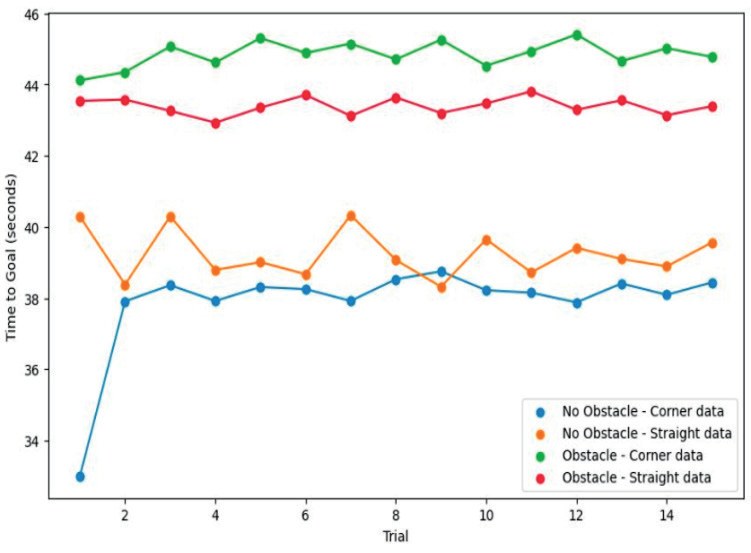
- Time-to-goal increases with distance and obstacles; trials consistent overall
- CPU on host ~90–95% during full Nav2 operation — plan compute budget carefully
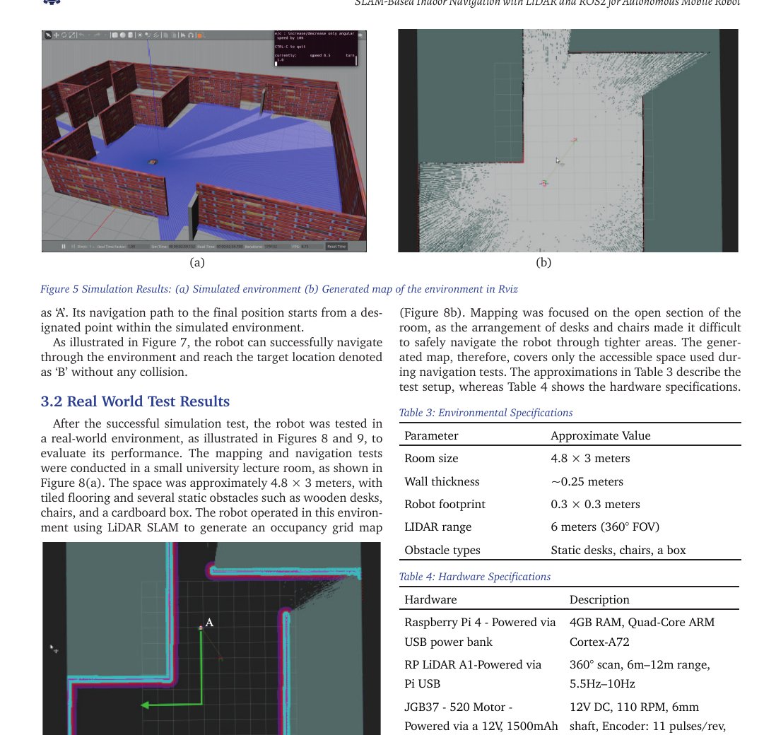
Simulation environment and generated RViz map.
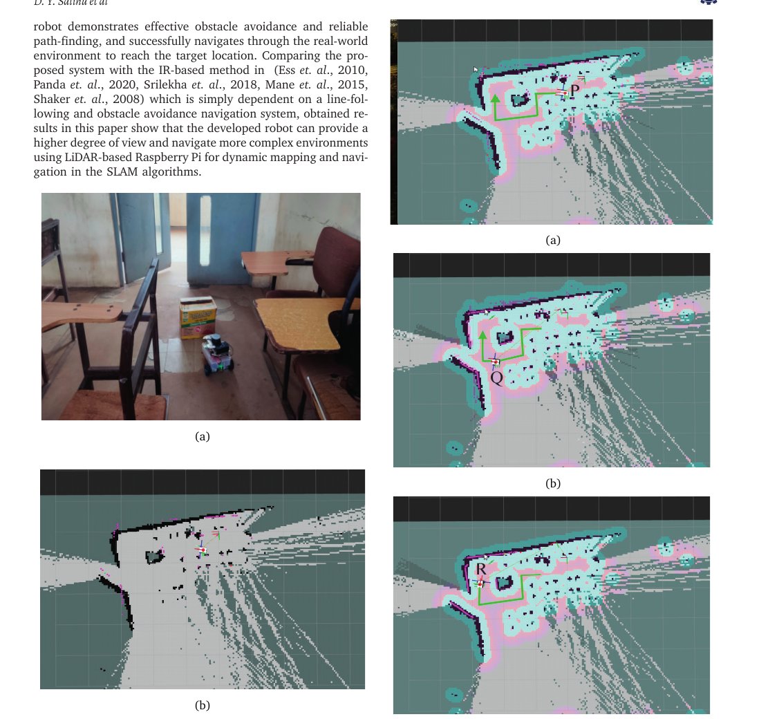
Real-world motion and occupancy map of lecture-room test.
RViz positions: start, intermediate, goal on LiDAR map.
Suggested Student Project Scope
- Assemble differential-drive chassis with encoders + LiDAR + RPi + Nano
- Bring up
/scanand/odom; verify TF tree - Map a room with slam_toolbox + teleop; save map
- Run Nav2 to multiple goals; log time-to-goal and collisions
- Optional: tune PID on different surfaces; compare open vs cluttered paths
- Report + PPT: architecture, wiring, launch files, RViz screenshots, limitations (stairs, glass, dynamic people)
Why Choose Us?
Bangalore robotics lab support for ROS2 SLAM AMRs.
Full Stack
LiDAR, ROS2, Nav2, Arduino PID and Gazebo/RViz workflow.
Paper-Aligned
Hardware list, SLAM parameters and test metrics from published AMR work.
Code Starters
Arduino PID sketch and ROS2 launch order for student labs.
Report & Viva
University-format documentation and viva Q&A on SLAM vs line-following.
FAQ
SLAM Robotics Lab — Bangalore
LiDAR, ROS2 and autonomous navigation project support.
360°
Map
Planner
PID
Pi 4
RViz
Drive
Support