ROS Gmapping AMCL move_base
This project implements SLAM and autonomous navigation in ROS for a robot with variable-diameter wheels (water-bomb / origami-inspired multi-link design). Fixed kinematic models fail when radius and wheelbase change; a parameterized kinematics + encoder–IMU fusion pipeline feeds reliable /odom into Gmapping and move_base.
Variable Diameter Wheel Robot SLAM — Origami Robot ROS Navigation. URL: https://www.projectsatbangalore.com/SLAM/slam-based-autonomous-navigation-robot-using-ros/
Reference: Zhao, Zhang & Shang, “Research of origami robot ROS-based SLAM and autonomous navigation,” Research Square preprint (2023), DOI: 10.21203/rs.3.rs-2703022/v1.
Tools Used
Water-Bomb Wheel & Parameterized Kinematics
The water-bomb origami unit folds so that pushing the end face increases wheel radius. Multi-link reinforcement improves load capacity. Equivalent circular diameter from octagonal contact:
d = 8 D sin(π/8) / π
Differential-drive style relations map body velocity \(v,\omega\) to left/right wheel rates; when diameter changes, track width \(w\) also changes — parameterized by actuator extension \(L\).
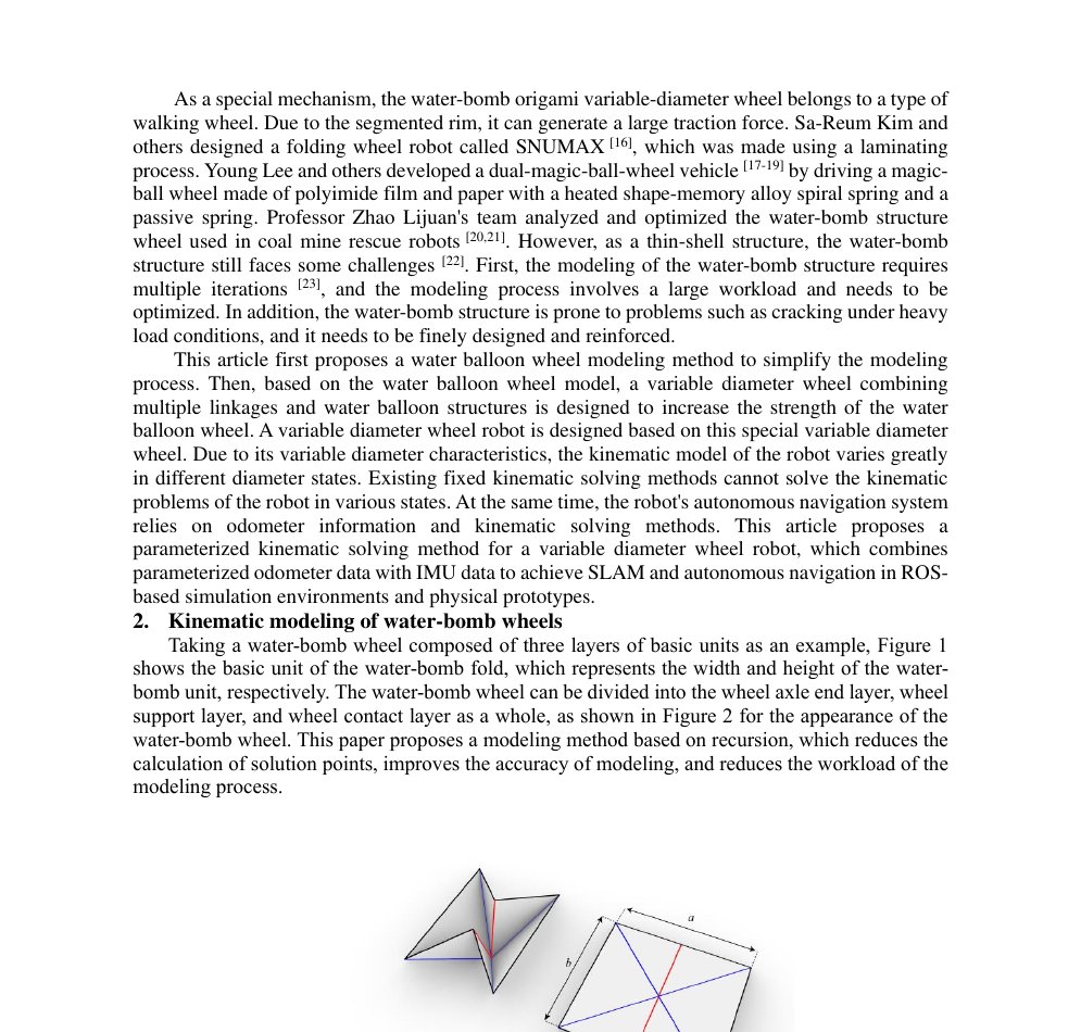
Water-bomb basic unit and wheel appearance (paper Figures 1–2 style).
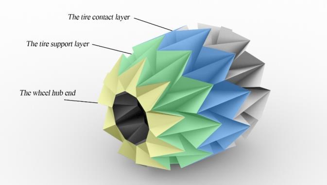
Hub / support / contact layers of the variable-diameter wheel.
Circuit & Data Flow
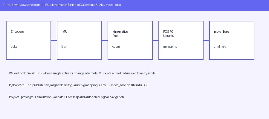
Encoders + IMU → parameterized kinematics → ROS /odom → Gmapping / move_base.
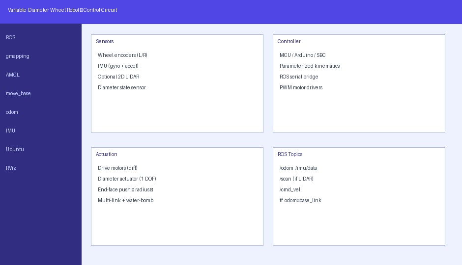
Sensors, controller, actuation and ROS topics for the variable-wheel platform.
Typical hardware: Hall encoders on drive motors, MPU6050 IMU, diameter actuator (push rod), optional LiDAR for Gmapping, ROS PC on Ubuntu.
ROS Ubuntu Stack
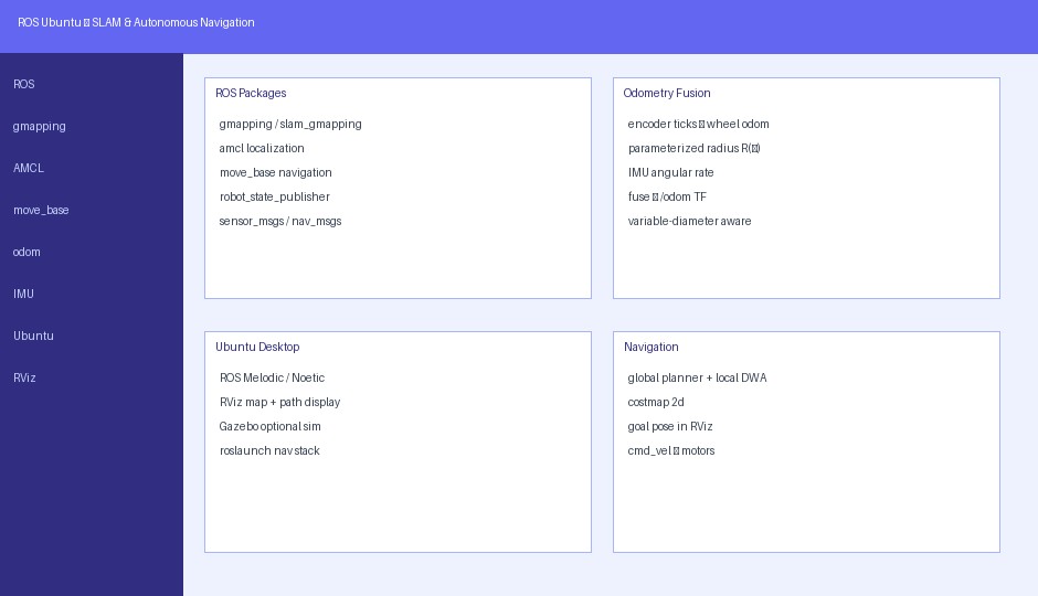
ROS packages: gmapping, AMCL, move_base, odometry fusion on Ubuntu.
- Mapping: Gmapping with fused odometry input
- Localization: AMCL on saved map
- Navigation: move_base (global + local planners, costmaps)
- Visualization: RViz paths and costmaps; Gazebo for ~1000 m² indoor sim
Without parameterized odometry, maps show misalignment; with it, obstacle edges stay clear (paper prototype comparison).
Sample Code — Parameterized Odometry (Python sketch)
# Illustrative ROS1 node: publish nav_msgs/Odometry from encoders + radius state
import rospy, math
from nav_msgs.msg import Odometry
from geometry_msgs.msg import Quaternion
from tf.transformations import quaternion_from_euler

class ParamOdom:
    def __init__(self):
        self.x = self.y = self.th = 0.0
        self.n_sum = 1000          # encoder ticks per wheel rev
        self.D = 0.20              # diagonal of octagon [m] — update from diameter sensor
        self.w = 0.35              # track width [m] — also functions of L
        self.pub = rospy.Publisher('/odom', Odometry, queue_size=10)
        # subscribe encoder deltas and IMU yaw rate as needed

    def d_equiv(self):
        return 8 * self.D * math.sin(math.pi / 8) / math.pi

    def step(self, dn_l, dn_r):
        dl = math.pi * self.d_equiv() / self.n_sum
        ds = 0.5 * (dn_l + dn_r) * dl
        dth = (dn_r - dn_l) * dl / self.w
        self.x += ds * math.cos(self.th)
        self.y += ds * math.sin(self.th)
        self.th += dth
        # TODO: fuse with IMU yaw (complementary / simple KF as in paper)
        o = Odometry()
        o.header.stamp = rospy.Time.now()
        o.header.frame_id = 'odom'
        o.child_frame_id = 'base_link'
        o.pose.pose.position.x = self.x
        o.pose.pose.position.y = self.y
        q = quaternion_from_euler(0, 0, self.th)
        o.pose.pose.orientation = Quaternion(*q)
        self.pub.publish(o)

# Launch order (Ubuntu ROS):
# roscore
# rosrun your_pkg param_odom_node
# roslaunch gmapping ...
# rosrun map_server map_saver -f map
# roslaunch amcl ...  +  move_base
Arduino — encoder pulse count (snippet)
// Count ticks; send deltas over serial to ROS bridge each 10 ms
volatile long leftTicks = 0, rightTicks = 0;
void leftISR()  { leftTicks++; }
void rightISR() { rightTicks++; }
void setup() {
  attachInterrupt(digitalPinToInterrupt(2), leftISR, RISING);
  attachInterrupt(digitalPinToInterrupt(3), rightISR, RISING);
  Serial.begin(115200);
}
void loop() {
  static unsigned long t0 = 0;
  if (millis() - t0 >= 10) {
    noInterrupts();
    long dl = leftTicks, dr = rightTicks;
    leftTicks = rightTicks = 0;
    interrupts();
    Serial.print(dl); Serial.print(','); Serial.println(dr);
    t0 = millis();
  }
}
Simulation & Prototype Results (Paper)
- Gazebo indoor world (~1000 m²) with fixed obstacles; URDF/Xacro robot model
- Gmapping maps with flat walls when using fused parameterized odometry
- move_base sequential goals with shortest paths and obstacle avoidance in RViz
- Physical maps without parametric odometry: clear misalignment
- With parametric odometry: sharp obstacle edges; landmark sizes closer to ground truth
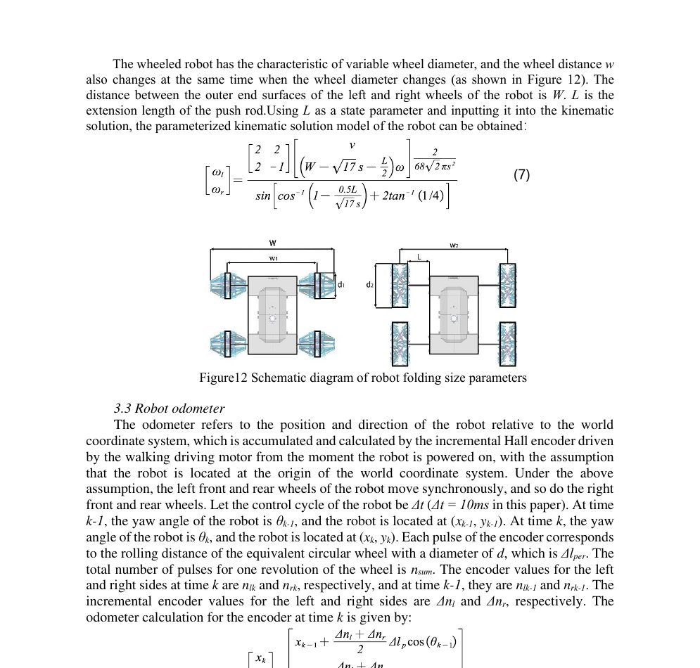
Simulation / mapping section from the reference paper.
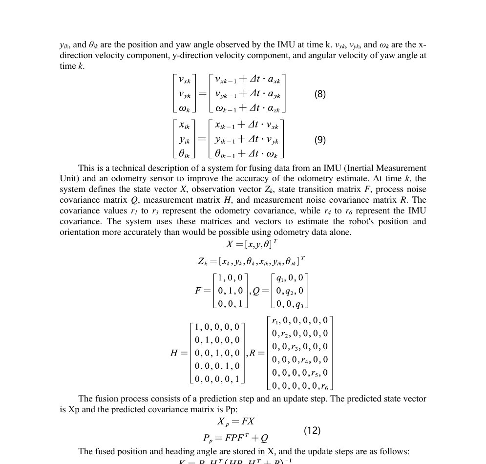
Prototype mapping comparison and path-planning discussion.
Suggested Student Project Scope
- Differential-drive chassis (fixed or variable radius) + encoders + MPU6050
- Publish parameterized
/odom; verify TF odom→base_link - Gmapping a room; save map; run AMCL + move_base goals
- Compare maps with vs without correct wheel radius in the model
- Optional: simple diameter actuator and update \(d,w\) online
- Report: kinematics derivation, launch files, RViz/Gazebo screenshots, error table
Why Choose Us?
ROS Navigation Stack
Gmapping, AMCL, move_base and RViz workflow for final-year labs.
Variable Wheel Insight
Why fixed odometry fails and how parameterization + IMU fusion helps.
Code Starters
Python odometry publisher and Arduino encoder sketch.
Report & Viva
University-format documentation aligned with published ROS SLAM work.
FAQ
ROS SLAM Lab — Bangalore
Map
Localize
Nav
Fusion
Diameter
RViz
ROS
Support