Artificial Magnetic Conductor Antenna Project Topics
An Artificial Magnetic Conductor (AMC) is a periodic metallic structure printed on a grounded dielectric substrate that exhibits a reflection phase of 0° (unlike a perfect electric conductor which reflects at 180°) within a defined frequency band. This property makes AMC surfaces ideal as ground planes for low-profile antennas, eliminating the destructive interference that normally prevents horizontal dipoles and patch antennas from being mounted directly on metal surfaces.
AMC and Electromagnetic Band-Gap (EBG) structures are among the most active research themes in 2026 IEEE Transactions on Antennas & Propagation, IEEE AWPL and IEEE Access — covering wearable body-centric antennas, 5G/mmWave arrays, MIMO decoupling, reflectarrays, reconfigurable surfaces and metasurface lenses. Projects are simulated in HFSS, CST Microwave Studio, COMSOL Multiphysics and FEKO with full parametric studies, S-parameter validation and radiation pattern analysis.
AMC Antenna Specialisations We Cover
- AMC-backed low-profile microstrip patch antenna
- Mushroom-type and Jerusalem-cross EBG structures
- Wearable AMC antenna for WBAN & healthcare
- SAR reduction using AMC in body-worn devices
- MIMO antenna with AMC-based mutual coupling reduction
- 5G/mmWave AMC-assisted slot and dipole arrays
- Dual-band & triple-band AMC antenna for IoT/ISM
- Reconfigurable AMC (PIN diode / varactor tuning)
- Circularly polarised AMC patch antenna
- Textile AMC antenna for soldier / athlete monitoring
- Reflectarray with phase-agile AMC unit cells
- Metasurface-based antenna gain enhancement
- Ultra-thin AMC for conformal aircraft structures
- ML-assisted AMC unit-cell optimisation
AMC Patch
Low-profile AMC-backed patches with 0° reflection phase, high gain and reduced back-lobe.
EBG Structures
Mushroom, Jerusalem-cross and spiral EBG for surface wave suppression.
Wearable AMC
Textile and flexible AMC ground planes for WBAN, healthcare and athlete monitoring.
MIMO + AMC
AMC decoupling structures to reduce mutual coupling and improve isolation in MIMO.
5G / mmWave
Sub-6 GHz and mmWave AMC-backed arrays for 5G NR beam-forming.
Metasurface
Phase-gradient metasurfaces for beam-steering, focusing and holographic radiation.
Artificial Magnetic Conductor AMC
Industry-standard full-wave EM simulators and supporting tools used to design, optimise and validate all AMC antenna projects.
Project Overview & Technical Details
Abstract, simulation tools, fabrication dimensions and expected metrics for Artificial Magnetic Conductor Antenna.
Abstract
The Artificial Magnetic Conductor Antenna project focuses on the electromagnetic design and performance analysis of an antenna structure intended for its target wireless application. The study considers the antenna geometry, substrate or dielectric environment, conducting elements, excitation method, and surrounding boundaries so that the proposed configuration can be evaluated under realistic operating conditions.
The design process begins with suitable antenna dimensions and material parameters derived from the intended operating requirements. The intended operating frequency range is considered during the initial design and tuning. Key geometric parameters can be varied to study their influence on impedance matching, bandwidth, radiation behaviour, efficiency, and gain.
Full-wave electromagnetic simulation is used to examine the behaviour of the proposed Artificial Magnetic Conductor Antenna before fabrication. CST Studio Suite and Ansys HFSS are suitable for this type of antenna investigation because they support detailed electromagnetic field analysis and extraction of parameters such as S-parameters, resonant response, radiation patterns, gain, directivity, and field distributions.
During optimization, parameters such as feed position, element dimensions, spacing, substrate properties, and other project-specific geometric features can be adjusted to obtain the required response. Simulation results can be compared across design iterations to identify a practical configuration while reducing unnecessary fabrication trials and helping validate the expected antenna characteristics.
The completed study provides a structured basis for antenna fabrication and experimental verification. The simulated results can be used to prepare performance plots and design documentation, followed by measurements such as return loss, impedance response, radiation pattern, gain, or other application-specific characteristics. This approach supports systematic evaluation of the Artificial Magnetic Conductor Antenna for academic research, prototype development, and wireless communication applications.
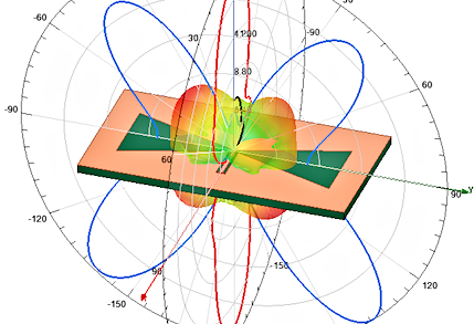
Simulation Tools Used
HFSS (Floquet ports), CST, FEKO, COMSOL RF; MATLAB phase extraction
Typical workflow: geometry → boundary conditions → parametric sweep → S-parameter & far-field post-processing → optimization.
Operating Frequency
2.4 / 5.8 GHz ISM, sub-6 5G, or custom HIS band
Antenna Dimensions (Typical)
Unit cell typically 0.1–0.2 λ0; overall AMC panel sized to antenna footprint; height ≪ λ0 for low-profile benefit
Feed Network
Host antenna feed (probe/microstrip); AMC is passive reflector/ground
Fabrication Details
Multi-layer PCB with vias (mushroom AMC) or planar interdigital/patch AMC cells on FR-4/Rogers
Key Performance Metrics
Reflection phase bandwidth, in-phase band, antenna gain improvement, back-lobe reduction, isolation
Deliverables for Students
Simulation project files (HFSS/CST), dimensioned drawings, S11 / Smith / pattern plots, comparison table (sim vs target), university-format report, PPT and viva Q&A support from Bangalore.
Contact us for full simulation setup, fabrication guidance, university-format report, PPT and viva Q&A.
FAQ — Artificial Magnetic Conductor Antenna Projects
AMC Antenna Project Lab — Bangalore
Inside our Antenna & Electromagnetics project lab — HFSS, CST Microwave Studio, COMSOL and FEKO workstations, Anechoic chamber access coordination, VNA measurement desks, and dedicated mentoring rooms for BE, MTech and PhD ECE & ECom scholars.
3D FEM Simulation
Studio
SAR Analysis
MoM Simulation
Design
Decoupling
Array Design
AMC Optimisation
Preparation
Sessions