The Nonlinear Dynamics
Ahsan Ali1, Sajid Iqbal2, Hafiz Abdul Muqeet3, Hafiz Mudassir Munir4, Syed Sabir Hussain Bukhari4, Jong‑Suk Ro5* & Zeeshan Akbar1 DC–DC converters has significant role in the applied power electronic systems, distributed power systems, computers, home appliances and communication equipment. A converter must remain within the specified range of operation. The main goal of this paper is to discuss the nonlinear behavior of forward converter and highlighted the application of the 0-1 test by applying it on the forward converter. As forward converter may contains electronic components, which cause instability in the system. So, it is necessary to understand its behavior when specifications of components are changed.
To study chaotic behavior, 0-1 test will be applied on the forward converter, which is a novel technique outperform in unearthing the subtle chaotic behavior in deterministic dynamical systems. The forward converter goes from period-1, period-2, period-4 and finally become chaotic when the load resistance is varied. This variation in the behavior of the forward converter are analysis through 0-1 test for chaos. Moreover, time series plot, phase portrait and Bifurcation diagram for forward converter is also drawn for the validation of results obtained from 0-1 test. Test algorithm is applied via MATLAB and simulation of forward converter via MultiSim by varying its load resistance.
The complex behavior of the system sometime describes by the word chaos. Chaos is one type of characteristics shown by the by complex systems. Quasi-periodicity and subharmonics are other kinds. Nonlinear dynamics are generally deal with the field of science in which dynamical behavior of the nonlinear system is discussed1. A differential equation usually defines the nonlinear system. Nonlinear system have a pivotal role in the analyses of natural phenomenon but in last few decade it also gains importance in the engineering research field2. Non- linearities in the power electronics is the key challenge to the engineer in modern era. The understanding of the chaos is necessary for every power electronics engineer. During the early stage of power electronics development nonlinear phenomenon quasi-periodicity, chaos and harmonics appeared while experimentation. The regular periodic operation is the primary objective of the power electronics engineer, so to avoid any unpredictable strange operation, the circuit parameters that creating problem or chaotic behavior need to be adjusted. Such adjustment of circuit parameter is done by trial and error method3. However, we require better understanding of circuit operation at various point to get more reliable design. Moreover, it may acquire new possible operat- ing regimes of power electronic system after getting enough understanding of circuit. Power converters exhibit chaotic behavior. Chaos is an unpredictable long-term behavioral disorder showed by the nonlinear dynamical system. In order to get knowledge about this phenomenon, various tools have been established4,5 Bifurcation diagrams are the well-known evaluation tool for the analysis of nonlinear system when one or more parameters are 7 changed. It is usually plotted in 2D plane by placing variable on x–y axis and varying variable on x-axis6.
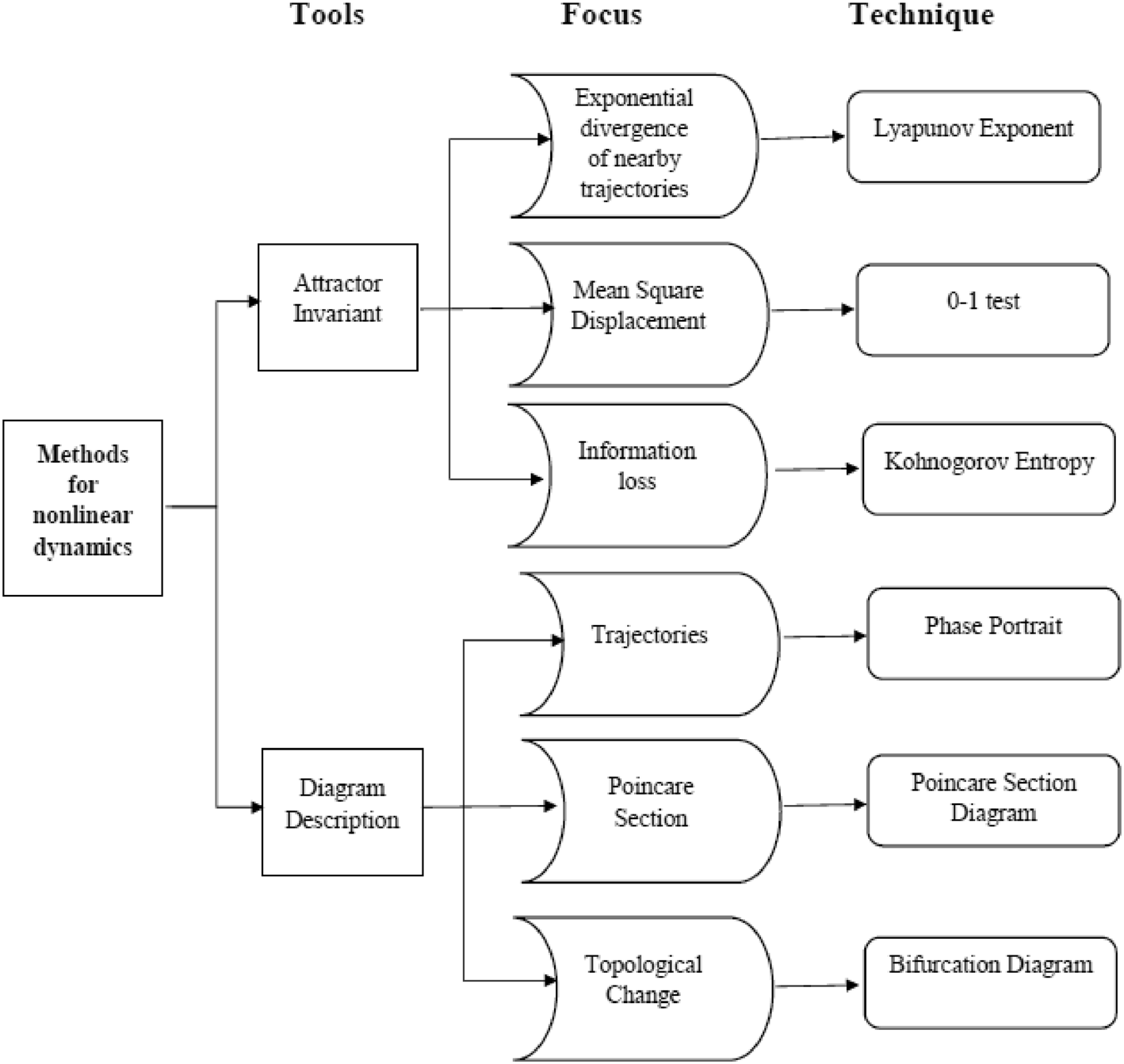
To draw higher order bifurcation diagram, extensive computation is involved. Power electronic use the discrete model to generate the bifurcation diagram through state variable7. The power electronics converters test by various techniques are summarized as below in Fig. 1. A phase portrait shows convergences and divergence trajectory towards the stable point7. Time domain waveforms show the steady state and the transient response.The time series complexity of power converters has been observed through various techniques. These methods were discussed in literature. These techniques are divided into three main groups, i.e. methods derived from nonlinear dynamics entropy and fractality8. The method used in this
Www.Nature.Com/Scientificreports/
research to determine the nonlinear dynamics of forward converter are 0-1 test, bifurcation diagram, Poincare map, and phase portrait is summarized shown in the Fig. 1. The chaotic and regular behavior of the deterministic dynamical system are studied through 0-1 test for chaos.
Unlike other test this test is simple, and it does not need to know the nature of the system. This test is easily appli- cable on the partial differential equation, ordinary differential equation, or experimental data. The test is binary in nature it gives result 0 or 1, 1 for the chaotic system and 0 for the periodic system9,10. This tool is widely used for detecting chaos in diverse field due to the ease in its implementation, wide range of application and evaluation.
Few examples where 0-1 testing is used recently on experimental data to discrete or continuous time system11. To detect chaos in a real-world system different technique are used. Lyapunov exponent is the one of them which is extremely sensitive to the noise12. Therefore, in many cases it is very difficult to implement. Lyapunov exponent requires phase space reconstruction to distinguish between the chaotic and regular dynamical system13.
After that many other different algorithms have developed and the most prominent one is 0-1, which directly applied on the time series 0-1 test developed by Gottwald and Melbourne which is not affected by noise10. This method takes time series data as input and gives 0 or 1 as the output according to the system dynamics: 1 for chaotic and 0 for regular. Moreover, Phase space reconstruction does not require in case of 0-1 test. This paper focuses on the nonlinear behavior of the forward converter, which is DC-DC converter. The variations and complications of nonlinear circuit and every converter topology show different problem which need to be examined. In this research work, forward converter is studied thoroughly through different nonlinear techniques like 0-1 test, bifurcation diagram, Poincare map, time series plot and phase portrait plot. The complex chaotic behavior of the system will be explored by varying control parameter. The simulation results will obtain from circuit simulator software. The experimentation and simulation result will then carefully observe to understand the nonlinear behavior of the system.
Literature Review
The nonlinear dynamics of the power converters are major concern for the engineers and researchers. The scholars studied chaos phenomenon in the power converters to understand their behavior. The research help to enhance the efficiency of the power converters and it also benefit for industries.
The basic converter topologies i.e. Buck, Boost and Buck-Boost converter have significant importance in converter technology. The research work had done on nonlinearity in buck, boost, and buck-boost converter topology. In this thesis7 pulse width modulation (PWM) buck and boost switching regulators simulated and carried out the nonlinear analysis. The buck-boost converter operated under the peak current control mode, the Figure 1. Nonlinear dynamical methods for times series data8.
Www.Nature.Com/Scientificreports/
storage energy in this dc system, used to examine the phenomena of nonlinear, chaos and bifurcation observed in14. This paper15 took current and voltage controlled buck converter for investigation of nonlinear phenomena and observed the bifurcation and chaos. The buck converter fed with the rectifier having ripple were studied in16 and discussed chaos phenomenon and bifurcation. In17 the author studied the chaos phenomenon in three topological power converters having closed loop. In18 the author showed the coexistence situation in flyback converter: two period orbits , period-1 and period-2 orbits and chaotic and period-1 orbits and lastly chaotic and period-2 orbits.
Flyback converter is one the most important in converter in power converters used in daily life. The relation- ship between iterative nonlinear mapping and dynamical system like DC-DC converter is discussed by David et al. in19 Flyback converter also produce nonlinearity at some point, the phenomenon of chaos in a UC3842 current programmed flyback converter was discussed in20. In this operation principle, mathematical models and discrete-time analytic solution derivations of the flyback converter were presented. Fei-Hu et al.21 explored the nonlinear behaviors in the UC3842 current-mode controlled flyback converter when the switching frequency altered. Ru Yang et al. had established the duplicate symbolic sequence of voltage-mode-controlled flyback converter and it had been applied as an example to identify various types of the bifurcation, in the bifurcation process of the system22. The duffing oscillator is the well known nonlinear circuit, the studied about critical situ- ation of the generating of the chaos by fractional derivatives and nonlinear damping in the duffing oscillator was examined by Wang et al.23. The system stability affecting by the fraction order term and non-linear factor. This influence on the system stability is studied using piecewise nonlinear oscillator24.
The nonlinearity was observed in forward converter by various researches. Bi et al. studied nonlinearities in forward converter by changing the values of load resistance, filter inductor and filter capacitor25. Discrete itera- tive mapping of voltage-mode controlled forward converter developed to explore the nonlinearity and obtained the bifurcation diagram with the input voltage, reference voltage and load resistor as bifurcation parameters26.
Jingmei et al. done reduction of EMI through chaos, for that purpose voltage-mode controlled forward converter circuit is used by Bi et al.27. Wei et al. discussed nonlinearity in forward convert through bifurcation phenomena when voltage regulated forward converter operated on both continuous and discontinuous mode28. Half-bridge converter was analyzed by Song et al.29 and its dynamics were studied by the author.
The nonlinear dynamics of system study through various technique like bifurcation diagram, Kolmogorov entropy, minimum embedding, correlation dimension, Poincare Map, Lyapunov exponent and many others. 0-1 test is one of the such method.The 0-1 test method is new technique to determine the chaotic and regular dynamics does not require phase space reconstruction30. This method takes time series data as input and gives 0 or 1 as the output according to the system dynamics whether it is chaotic or regular10,31,32.The two well-known system Rössler and Lorenz and two less-known system calcium oscillatory models and arc circuit are used to utilize in the comparison of the determination of the periodic and chaotic oscillation by sample entropy and 0-1 test for chaos33. The combination of the approximate entropy and 0-1 test for chaos is introduced in order examined the nonlinearity of the three degree of freedom mechanical system34. Adel et al. studied the chaotic behavior of the Fractional-order Arnold map by 0-1 test for chaos35.
Moreover, at the beginning the 0-1 test was implemented on the logistic map driven10, damped Kortweg de Vries equation and forced van der Pol36. Kim implement the 0-1 test on Local K spectrum of non-chaotic strange attractor37. Karsten Webel applied 0-1 test on the data obtained from German stock exchanges to verify results38. Falconer et al. analyzed the chaotic behavior of bipolar motor and studied the effectiveness of 0-1 test on experimental data39. Zachilas et al. briefly discussed about the implementation of 0-1 test on Hamiltonian systems they presented four Hamiltonian system two even and two odd order40 and their results were matched with 0-1 test. Baogui Xin et al. presented a discrete complex interaction model about industrial production and environmental quality in a closed area and then applied 0-1 test in order to validate the chaotic phenomenon of their model41. A simple method of detection chaos tool was presented by Daniel et al. by combining the several such tool of detecting chaos mainly 0-1 test and presented it implementation heart rate variability42. Michelle et al. applied the 0-1 test for chaos on an Aeroelastic System and compared the results with the attractor recon- struction method such as Lyapunov exponents43.
Furthermore, the 0-1 test gained lot of more attention because of its simplicity and research used it to study the chaotic dynamics of various systems. Adel Ouannas et al. used 0-1 test, entropy, bifurcation diagram and Co-complexity to analyzed the chaos in discrete fractional duffing system44. In this article the author discussed about the false negative result of the 0-1 test and presented ideas about how to avoid such result45 . In this paper46, two new techniques were discussed which are center of gravity and box counting. They also thoroughly studied about benefits and disadvantages of these methods. The dynamical behavior of the Henon–Lozi type map were studied by applying numerical tools which are: largest Lyapunov exponent, bifurcation diagram, 0-1 test and phase portrait. It displayed that the map shows a range of numerous dynamical properties from coexisting attrac- tors to chaos47. This research work in48 explored the post-flutter nonlinearities because of the wing high aspect ratio. The results of aeroelastic system were then used to analyzed for the comparison of attractor reconstruction and 0-1 test for chaos.
Methodology
Overview of the binary 0‑1 test. The 0-1 test is initially presented by Gottwald and Melbourne10. It is a binary test for chaos detection in dynamical system which does not require phase space reconstruction. It uses the time series of underlying system. The test has been successfully implemented to flows and maps, but in this study, it is implemented on the continuous system such as forward converter. The chaotic and regular behavior of the deterministic dynamical system are studied through 0-1 test for chaos. Unlike other test this test is simple, and it does not need to know the nature of the system.
Www.Nature.Com/Scientificreports/
This test is easily applicable on the partial differential equation, ordinary differential equation, or experimental data. The test is binary in nature it gives result 0 or 1, 1 for the chaotic system and 0 for the periodic system9,10,39. This tool is widely used for detecting chaos in diverse field due to the ease in its implementation, wide range of application and evaluation. The flow chart how the research is conducted given in Fig. 2.
Condition for the implementation of 0‑1 test. For the implementation of 0-1 test the following condi- tions must be fulfilled to get the require result from the test.
1. Enough large time series data is required to adequately determine the asymptotic behavior of MSD10,39. 2. The short transient response of the system require to removes in order to avoid the false result and time series taken for test after removal of transient response36,49.
3. The data should be deterministic and stationary. The 0-1 test may fails to produce result in some cases for example when the time series used to implement the test are obtained from the near edge of the chaos32. Moreover, when the dimension of the attractor is too large and extremely long transient the 0-1 test is impracticable36.
Effects of number of data points. The number of data points have impact on the results of 0-1 test. To avoid the false results the number of data points must be addressed while implementing the results. Finite size effect in three ways10. The time series need to be large enough to explore the dynamics of the system this problem affecting all test of chaos. The limit n ≪N while calculating the mean square displacement. So, we require to choose ncut ≪Nand ncut = N/10 The asymptotic behavior of Mc(n) or Dc(n) required ncut and N, which may require sufficiently large data. In case of small number of data points the asymptotic growth is not dominating to visualize the results.
Effect of oversampling on continuous times series data.
For Continuous Time Series There Is A Well-
known oversampling issue that must be addressed10,31,50.
Signal Is More Than 10X Greater The Mean Absolute
difference successive values in signal.
Applicable
Figure 2. Flow chart of research methodology.
Www.Nature.Com/Scientificreports/
1. One method which suggested by Gottwald and Melbourne is to observe the Poincare’s Section 2. A second, perhaps more usual, approach by visual inspection30. 3. Third method is more refined method discussed in10,51 use of the first minimum of mutual information.
Simulation Circuit Of Forward Converter
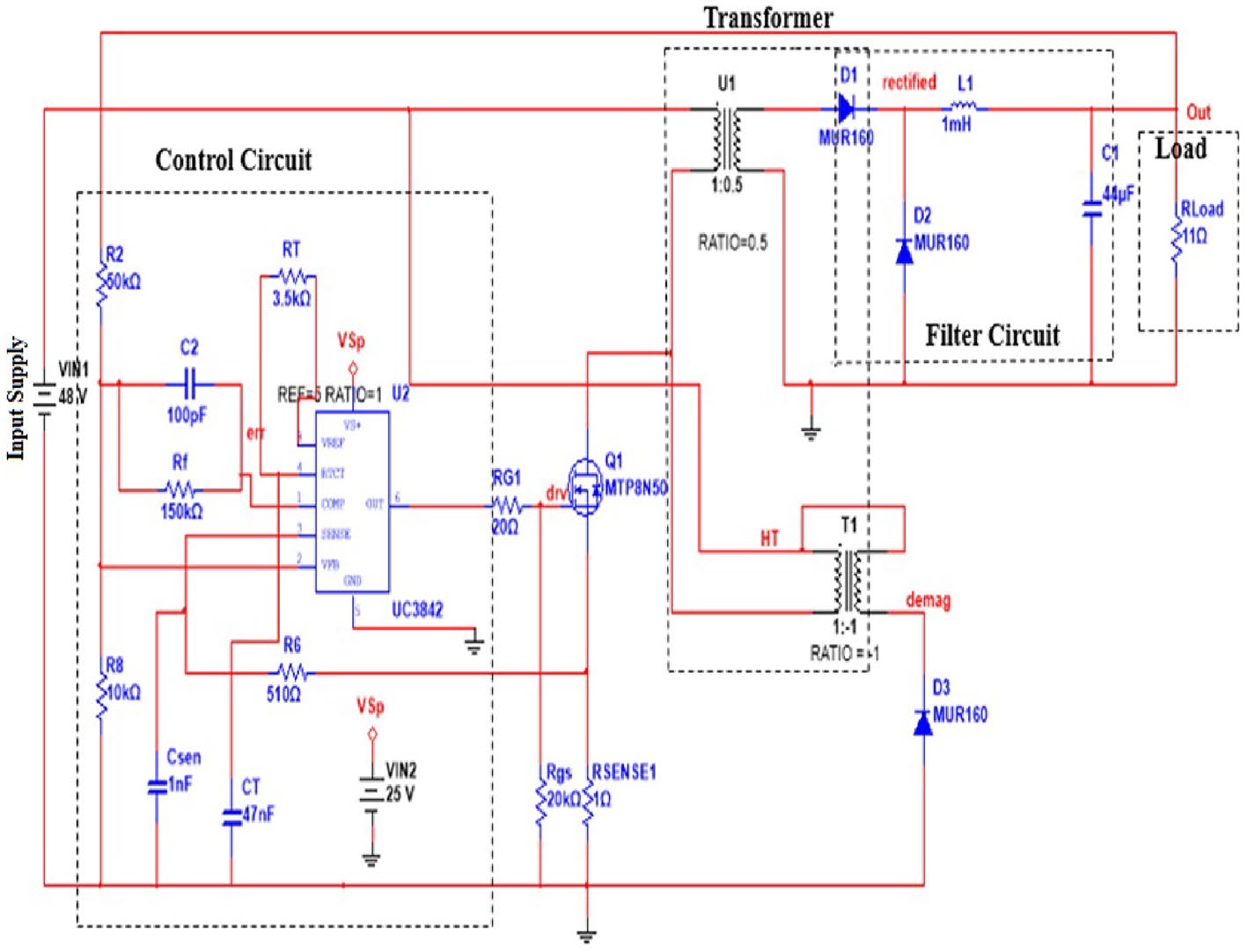
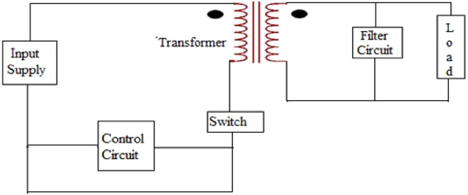
A forward converter has less output DC voltage than the applied DC voltage and its input and output is isolated from input by transformer. Figure 3 shows the schematic diagram of a current mode forward converter. Circuit in Fig. 4 shows the simulation circuit of forward converter. The circuit is simulated in the MultiSim. The converter is simulated first, then the waveform of the inductor current and output voltage is obtained. The phase portrait and bifurcation diagram of the converter are also drawn. The circuit parameters are given in Table 1.
Results And Discussion
The simulation and experimentation circuits were shown in “Simulation circuit of forward converter”. In this section, results obtained through simulation and experimentation were analyzed through nonlinear techniques, which were 0-1 test, phase portrait, time series plot and bifurcation diagram discussed in “Methodology”.
Figure 3. Schematic diagram of a current forward converter. Figure 4. MultiSim simulation circuit of forward converter.
Www.Nature.Com/Scientificreports/
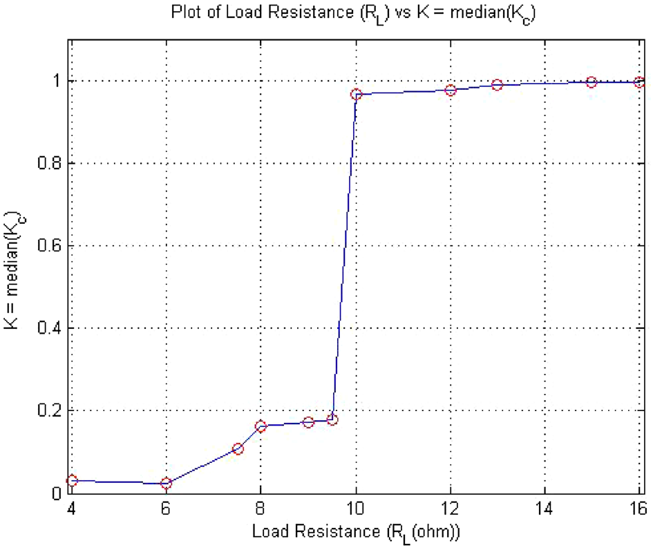
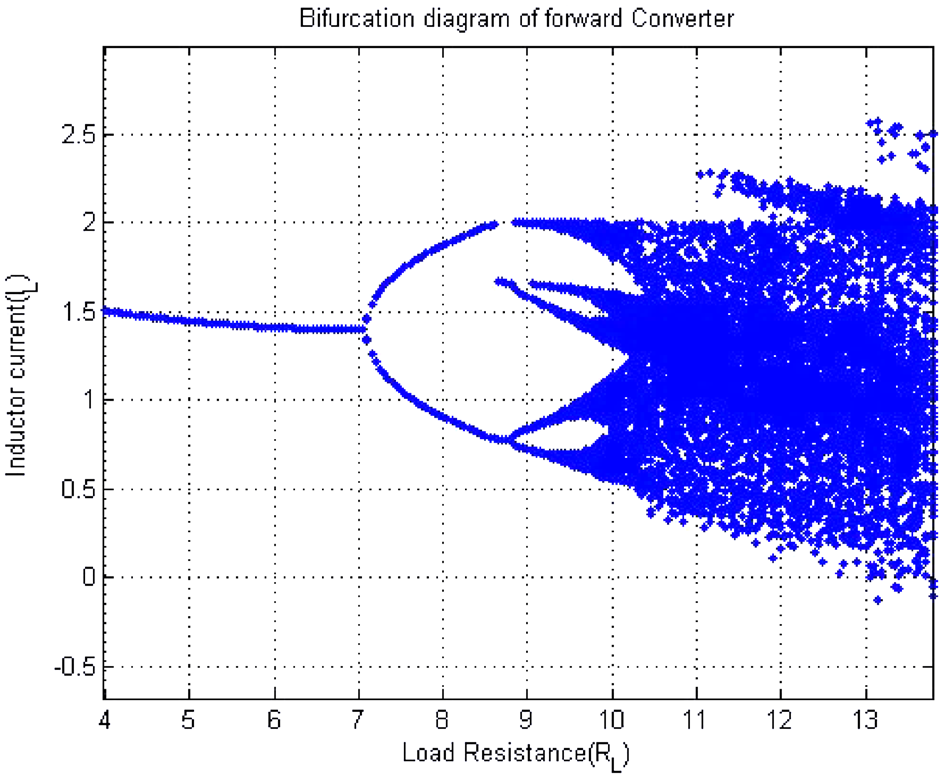
Verification of the 0‑1 test via bifurcation diagram. Period doubling route to chaos is a salient feature of chaotic systems. The dynamic chaotic system was observed through bifurcation phenomenon. How does chaos occur after a period? This phenomenon pictorially had observed through bifurcation diagram as shown in Fig. 5. The result obtained from test were clearly matched with bifurcation diagram shown in Figs. 5 and 6, which was validated 0-1 test. In Fig. 5, the value of k changing from 0 to 1 as the value of RL changing from RL = 4 to RL = 16 . Similarly, with RL as the bifurcation parameter, the forward converter bifurcation dia- Table 1. Circuit parameters of forward converter.
1 : 0.5 : 1
Figure 5. Bifurcation diagram of forward converter when RL changing from RL = 4 to RL = 12 . Figure 6. RL vs K plot of 0-1 test for forward converter when RL changing from RL = 4 to RL = 16 .
Www.Nature.Com/Scientificreports/
gram was drawn in MatLab. The current via inductor were considered for analyzing the bifurcation. RL was on x-axis and Inductor current IL on y-axis. Figure 5 shows bifurcation diagram of forward converter. The figure had clearly showed that period-1 at RL = 4 , period-2 started at RL = 7.5 , period -4 at RL = 9 and chaos at RL = 11 .
0‑1 test results of forward converter. In this section, the result of the forward converter after the imple- mentation of the 0-1 test were examined and discussed in detail.
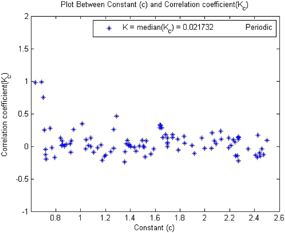
0‑1 test results for forward converter at period‑1. Times series data was acquired from the simulation circuit of forward converter at RL = 4 ,which gave period 1. When 0-1 test algorithm was applied on this time series data which was discussed in “Methodology”, it gave the values indicator K = 0. The plot between p and q was bounded shown in Fig. 7. However, for periodic system the value of K must be near to zero and the value of K = 0.02173 for this time series shown in Fig. 8 and the mean square displacement plot did not show any asymptotic growth shown in Fig. 9. Hence, with the help of above results, the 0-1 test confirms that the time series was periodic.
Therefore, forward converter showed periodic behavior when its load resistor was equal to 4 . Figures 7, 8 and 9 showed the forward converter had periodicity in their behavior and all three plot support the argument made by the 0-1 test methodlogy.
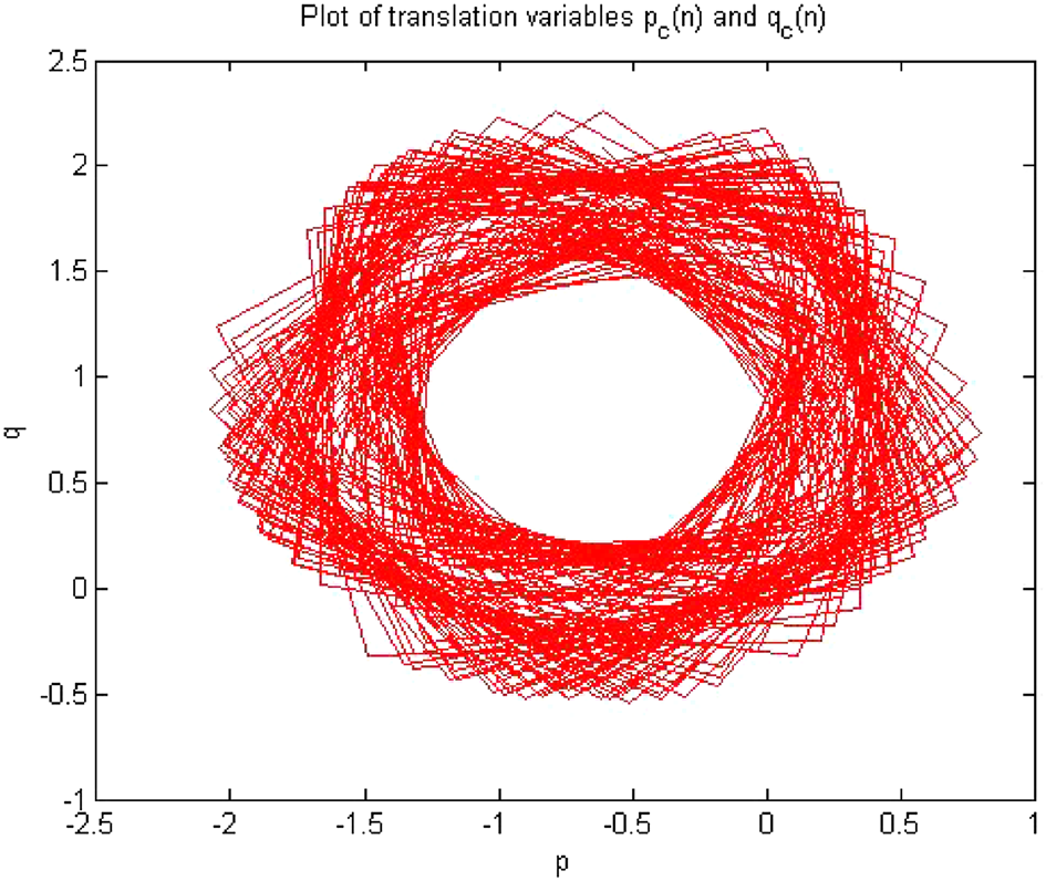
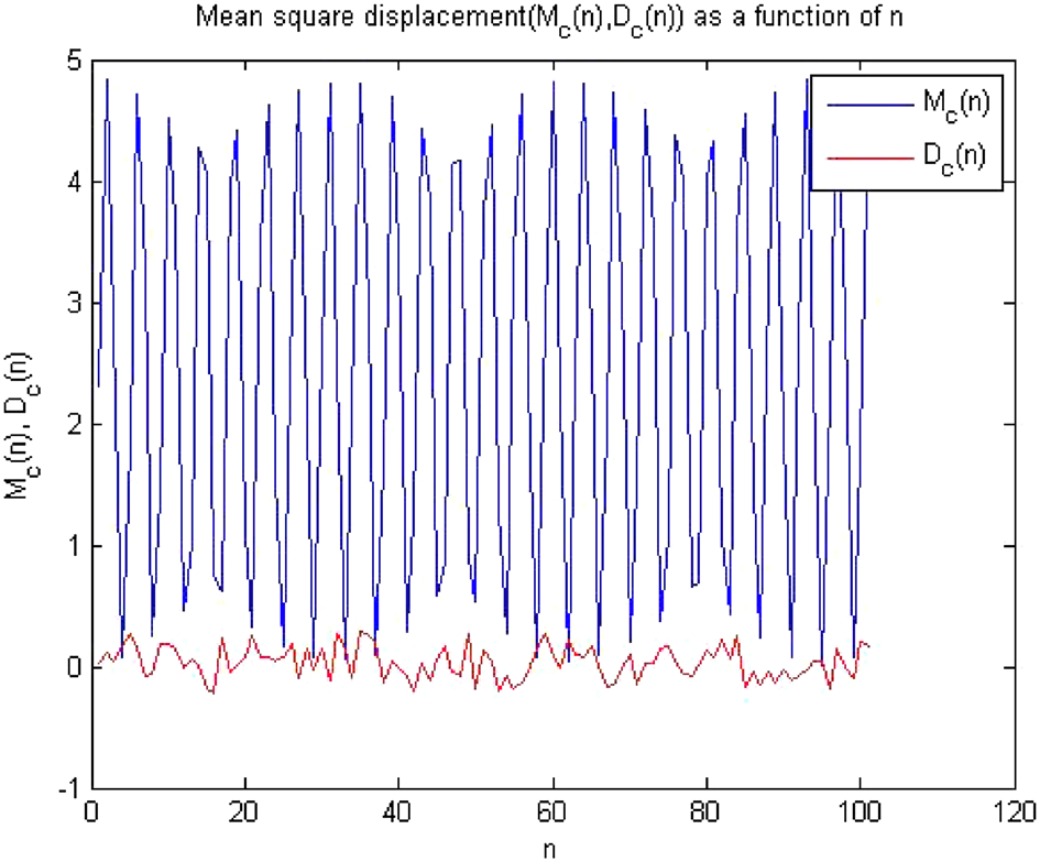
0‑1 test results for forward converter at period‑2. Figures 10, 11 and 12 shown the results of 0-1 test when time series was analyzed at RL = 7.5 The forward converter had period-2 at this value of resistor. The outputs of the Figure 7. Plot p vs q showed bounded shaped hence its is periodic.
Figure 8. Plot of c vs Kc shows periodic behavior as value of K = 0.02173.
Www.Nature.Com/Scientificreports/
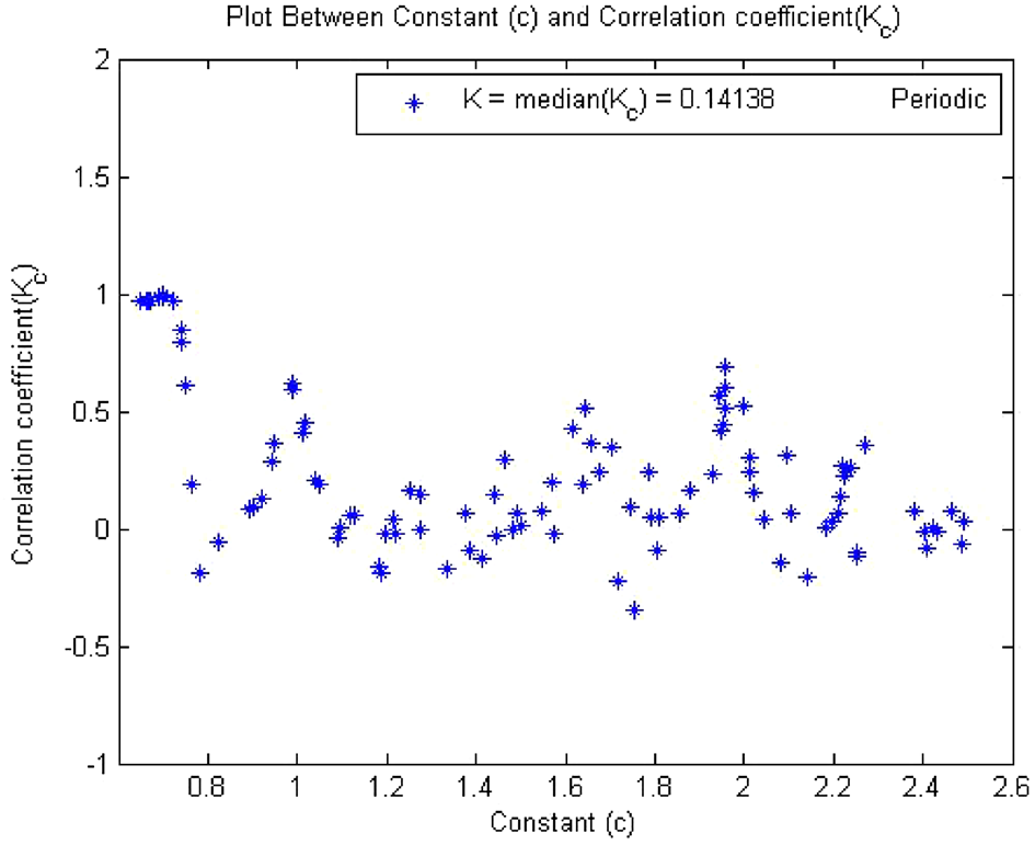
Figure 9. Plot of MSD vs time corresponding to periodic dynamics. Figure 10. Plot of p vs q shows bounded shape having regular behavior. Figure 11. Plot of c vs Kc have K = 0.141 so the dynamics ids periodic.
Www.Nature.Com/Scientificreports/
0-1 test proved that the system had periodicity in its behavior as the value of indicator K approaches to zero i.e., K = 0.141, p and q graph was also bounded and there was no asymptotic growth in mean square displacement plot.
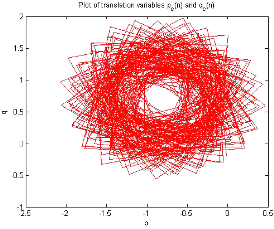
The plot in Figs. 10, 11 and 12 indicated that converter had regular dynamics as all the results showed perio- dicity according to the 0-1 test. 0‑1 test results for forward converter at period‑4. The converter showed period-4 at RL = 9 , when times series at this value of load resistance were analyzed through the algorithm of 0-1 test. The results obtained has clearly indicates that the time series was periodic. Figures 13, 14 and 15 shows that the dynamics of the converter was regular and it had indicator K = 0.189, p and q graph were almost bounded and there was no asymptotic growth in mean square displacement plot. The behavior of the forward converter was regular which is evident from Figs. 13, 14 and 15. as all the plots were matched with the conditions for periodicity discussed in the meth- odology of 0-1 test in “Methodology”.
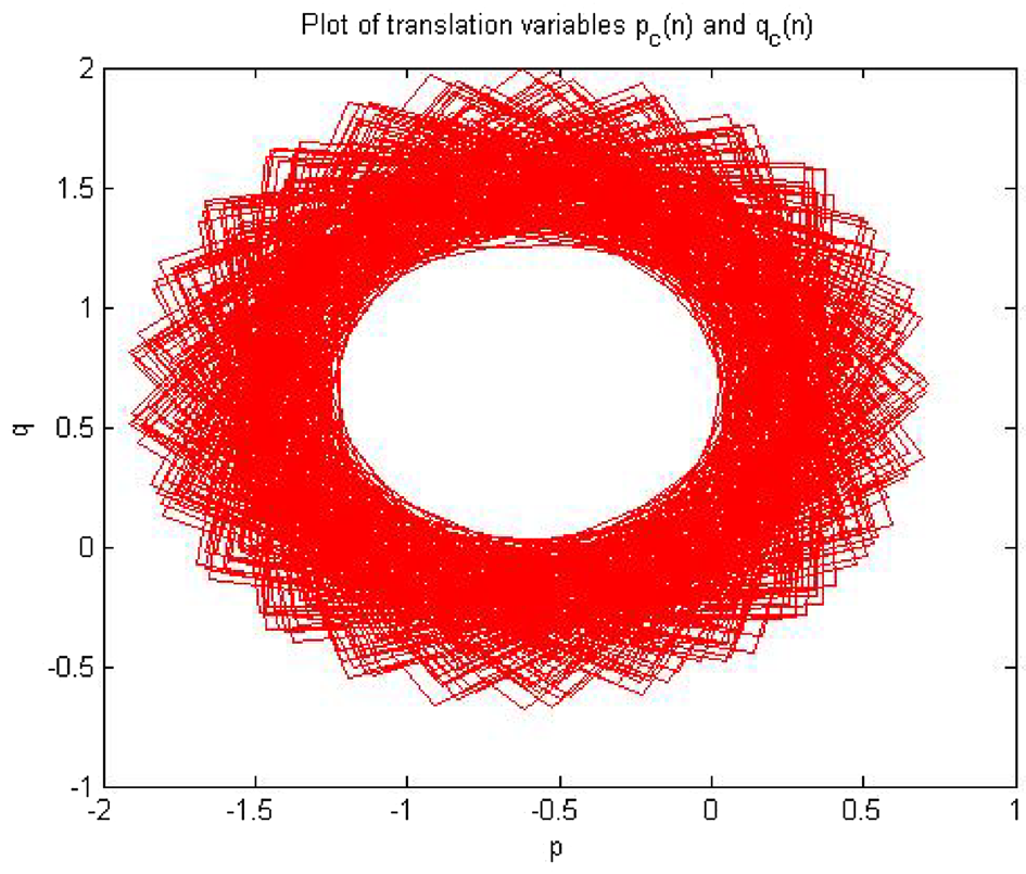
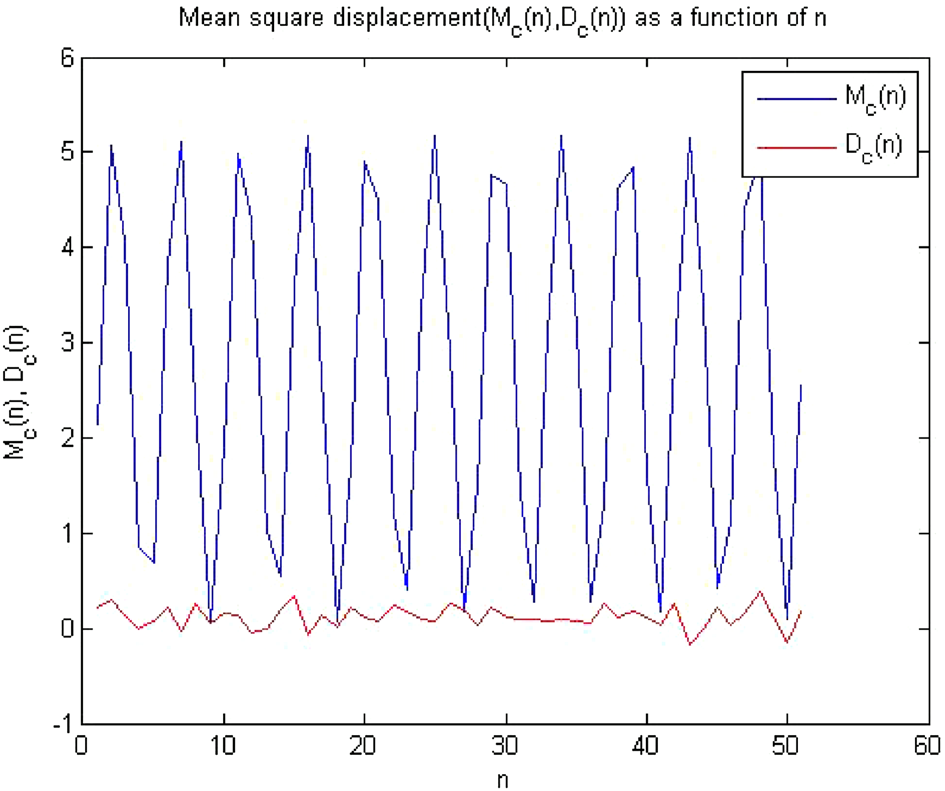
0‑1 Test results for forward converter at chaos. Times series data were obtained after the simulation circuit of forward converter at RL = 11 in MultiSim, when 0-1 test algorithm was applied on this time series data, it gave the value of indicator K = 0.983, which was approximately equal to 1 shown in Fig. 16. The plot between p and q had shown Brownian motion type shape in Fig. 17 and the mean square displacement plot had also displayed asymptotic linear growth shown in Fig. 18. Hence, with the help of above results, the 0-1 test confirms that the time series was Chaotic. Therefore, forward converter had shown chaotic behavior when its load resis- tor was equal to RL = 11 . After observing the plots at at RL = 11 the dynamics of the forward converter Figure 12. MSD vs time plot there is no asymptotic growth, so the dynamics is regular.
Figure 13. Plot of p vs q shows periodic behavior as it has bounded shape.
Deployment In Out-Of-Position Situations
D. Bendjaballah1, A. Bouchoucha1, M. L. Sahli1,2* and J-C. Gelin2
Abstract
Side-impact collisions represent the second greatest cause of fatality in motor vehicle accidents. Side-impact airbags have been installed in recent model year vehicle due to its effectiveness in reducing passengers’ injuries and fatality rates. In meeting these requirements, simulations of folding and deploying airbags are very useful and are widely used. The paper presents a simulation method for the deploying airbags using three materials in different working conditions. Finite element analysis is primarily used to evaluate this concept. In these simulations, the gas flow is described by the conservation laws of mass, momentum, and energy. The numerical results indicate that the FE method in this paper is capable of capturing airbag deploying process accurately.

Keywords: Airbag simulations, Out-of-position, Crash, Modeling, Out-of-position
Background
The passive safety of cars has become a very high prior- ity issue for the automotive industry. Today, there are not only one or two airbags in a car; certain models have ten times more than that. With the increasing usage of airbags, the number of accidents where the airbag itself can cause an injury to the occupant also increases
(Augenstein Et Al. 2003; Gabauer And Gabler 2010;
Audrey et al. 2011). As is well known, safety belts are also now devices designed to provide protection to the users of vehicles during crash events, minimizing the loads necessary to adapt their movement to the move- ment of the car (Freesmeier and Butler 1999; Schmitt et al. 1997). In general, the seat belt is designed to restrain the occupant in the vehicle and prevent the
Occupant From Having Harsh Contacts With Interior
surfaces of the vehicles. The airbag acts to cushion any impact with vehicle structure and has positive internal pressure, which can exert distributed restraining forces over the head and face. As a safety component of auto- mobile, an airbag decreases occupants’ injury likelihood effectively in case of an accident (Ruff et al. 2007). These safety elements can reduce the death rates on the roads, and its protection effects have been widely approved (Crandall et al. 2001; Teru and Ishikawa 2003). With computational tools such as finite element methods designed for dynamic contact problems, crashworthiness simulations can now be used with reliable accuracy to evaluate occupant protection in various collision condi- tions with safety metric/parameters such as acceleration, head injury criteria, intrusion distance, intrusion vel- ocity, and neck forces (neck injury risk or whiplash).

Thus, new types of airbag products are being developed to handle different collision scenarios.
Become Standard Equipment On Most New Passenger
vehicles (Braver and Kyrychenko 2004; Teng et al. 2007; Yoganandan et al. 2007). The airbag cushion is com- posed of a woven fabric which is rapidly inflated during a car crash. The airbag dissipates the passenger’s kinetic energy thereby reducing injury through biaxial stretching of the fabric bag and escaping gas through vents. There- fore, the performance of the airbag is greatly influenced by the mechanical properties of the fabric. Generally, air bags are designed to deploy in a crash that is equivalent to a vehicle crashing into a solid wall at 8 to 14 mph.

Air bags most often deploy when a vehicle collides with another vehicle or with a solid object like a tree. There are various types of airbags: frontal, side-impact, and curtain airbags. In general, the passenger side airbags are usually larger than the driver airbags (see Fig. 1).
Besançon, France
© The Author(s). 2017 Open Access This article is distributed under the terms of the Creative Commons Attribution 4.0 International License (http://creativecommons.org/licenses/by/4.0/), which permits unrestricted use, distribution, and reproduction in any medium, provided you give appropriate credit to the original author(s) and the source, provide a link to the Creative Commons license, and indicate if changes were made.

Bendjaballah et al. International Journal of Mechanical
Doi 10.1186/S40712-016-0070-2
Extensive studies have shown that the airbag deploy- ment in load cases consists of two occupant loading phases: a punch-out effect where the airbag bursts out of its container with the airbag and airbag module cover accelerating towards the occupant and a second loading phase during which the airbag is taking on its deployed shape and volume (membrane-loading effect). Bankdak et al. (2002) developed an experimental airbag test system to study airbag-occupant interactions during close proximity deployment. The results provided insight for simulating the effect of inflation energy and mass flow on target response. Bedard et al. (2002) found that while left-side (driver-side) impacts accounted for only 13.5% of all crashes, the fatality rate among these
Crashes Was 68.3% In Comparison To Front Impact
(48.3%), right-side impact (31.3%), and rear impact (38.4%). These studies underscore the importance of oc- cupant safety during side-impact collisions. In the last years, the current market requested to reduce the time and cost airbag development. In order to achieve this result, virtual simulations play an important role since they allow to minimize the number of experimental tests (Pei et al. 2013; Cao et al. 2014). Several simulation models of airbag were established (Wang et al. 2007). It is feasible to optimize the parameters of airbag deploy- ment using simulation technology. Experimental and numerical studies have quantified injury risks to close- proximity occupants from deploying side airbags. These studies have focused on the prevention of the most ad- verse effects of airbag deployment (Duma et al. 2003).
Other studies have proposed airbag characteristics to minimize particular biomechanical responses (Haland and Pipkorn 1996). In a more recent study, Marklund and Nilsson (2003) compared deformation patterns with experimental data as well as the computational costs associated with three different airbag deployment simu- lation methods; they concluded that the SPH method is relatively inexpensive and produces incremental deform- ation patterns that compare most closely to the experi- mental results. The process of inflation of an airbag is one of the determining factors in saving lives. The duration from the initial impact of the crash to the full inflation of an airbag is about 40 ms, and during this time, the airbag goes from being in a folded state to a fully inflated state, with a high internal pressure. After achieving this state, the airbag begins to deflate, thus providing a nice cushion for the body impacting it.
Ideally, the person in the crash should come into contact with the airbag at this time. In the present study, a large volume passenger side airbag model is developed to handle different collision scenarios. The main aim is evaluate the performance of deploying of passenger side airbag using finite element methods (FEM).
Materials
The tensile specimens were made in different airbags (P: Peugeot, R: Renault, and VW: Volkswagen) with a length of 200 mm long and a width of 40 mm. Table 1 shows the mechanical properties of the airbag.
Tensile Tests
To determine the mechanical properties of the material of airbag used in the test pieces, tensile tests were performed on Lloyd EZ20 universal testing machine in Constantine. These tests were conducted using rect- angular samples. The axial force and axial displacement acquired during a test are converted into stress and the strain in order to be used for the fabric material model.
The continuous recording of the stress-strain data was performed during both the load and unload phases. A minimum of five samples were made in order to check the repeatability of the measurements. All the data was collected by using a PC-based data acquisition system and analyzed by commercial software. The picture frame test device that is made for this study is shown in Fig. 2.
Fig. 1 a Frontal and side airbags. b Oblique view of facet occupant model in sitting posture following airbag deployment (Lim et al. 2014)
0.150
Bendjaballah et al. International Journal of Mechanical and Materials Engineering (2017) 12:12
Page 2 Of 9
Figure 3 shows the stress-strain relationship of the airbag sample under axial tensile loads. The results are showing a linear increase in extension with the increas- ing stresses. This is an expected output and it confirms with the theoretical behavior of a sample subjected to tensile stress. The rupture strain values for different airbags (R/P/VW) were 0.322, 0.441, and 0.472, respect- ively. The measured elastic parameters (i.e., Young’s modulus E and initial yield strength) and Poisson’s ratio are summarized in Table 2. The tensile tests of the woven fabrics can show differences on mechanical prop- erties because woven fabrics can resist in-plane shear loads once the yarn lock-up angle has been reached. The differences of material property on material direction can affect the shape of fully deployed bag (see Fig. 3b).
Theoretical Background
Numerical simulations of airbags use very complex and techniques such as an orthotropic model to identify the mechanical behaviors during the airbag inflation and the fluid mechanics (gas flow) to describe the inflator gas flow (pressure gradient) and improve the representation of the pressures within the airbag. To model the airbag as an orthotropic model, three material constants have to be provided. Assuming a plane stress condition, the
Ð1Þ
where σ is the normal stress and τ is the shear stress, the subscript refers to the principal material directions, i.e., the fill and warp directions. Also, ε and γ are the strain components. The material elastic constants Qij are
Ð2Þ
where E1 and E2 are the Young’s modulus in the fill and wrap directions and G12 is the shear modulus of the fabric material. νij is the Poisson ratio of the material.
The gas exerts a pressure load on the airbag causing it to expand. This expansion puts the airbag under tensile stress lowering the expansion rate. In this study, heat conduction and heat transfer is not taken into account.
Fig. 2 A photograph of Lloyd EZ20 universal testing Fig. 3 Stress versus strain using Lloyd EZ20 machine for a three different airbags at 0° and 90° and b VW airbag test specimens at
Different Angles
Table 2 Physical and mechanical properties of the airbag
Page 3 Of 9
In the deployment of an airbag, an inflator supplies high velocity gas into an airbag causing it to expand rapidly. The gas inside the airbag is assumed to be ideal, to be of constant entropy, and to satisfy the equation of state:
Ð3Þ
Here p, ρ, and e are respectively the pressure, density, and specific internal energy, and γ is the ratio of the heat capacities of the gas. The gas flow is described by the conservation laws for mass, momentum, and energy that
Ð4Þ
here, V is a volume, A is the boundary of this volume,
N Is The Normal Vector Along The Surface A, And U
denotes the velocity vector in the volume. Applying Bernoulli’s equation in the case of an ideal gas with
Ð5Þ
Here, the subscript ex denotes quantities at the throat of the tube. Furthermore u, p, and ρ denote the quan- tities inside that part of the tube that is supplying mass.
Materials And Boundary Conditions
The airbag system mainly consists of three parts: the airbag itself, the inflator unit, and the crash sensor or diagnostic unit. Thus, to study the behavior of the airbag using FE simulations, we need to have an FE model of the airbag in the folded position. A FE model of the airbag was used to simulate the test condition as shown in Fig. 5. LS-DYNA® material model FABRIC (MAT_34) is used to simulate the airbag material. It is a variation of the layered orthotropic material model. Additionally, in the LS-DYNA® material model, fabric leakage can be accounted for. However, for this CAB material, the leak- age is almost negligible and therefore no leakage is specified. The mechanical properties can be determined from the physical test. Typical material properties for airbag fabrics are taken as given in Chawla et al. (2004a) (Table 3). These properties are used to simulate inflation process of airbag (see Table 1). The car dashboard is modeled as the rectangular thin plate using a MAT_RI-
Gid Material, And The Degrees Of Freedom Are Con-
strained in all the directions. The similar properties of thermoplastic polymer are assigned for contact purposes. The porosity of the fabric is assumed zero. The nitro- gen gas is taken for inflating the airbag. Properties of nitrogen gas and initial bag conditions are shown in Table 4. The example on which we perform the study is a typical passenger side airbag. The geometric de- tails have been measured from a commercially avail- able airbag. The initial state of the airbag is a closed rectangular whose sides are to be finished to 482 × 635 mm2 and is shown in Fig. 4.
Table 3 Material properties of airbag and rigid plate used in FE
–
Table 4 Initial values used for FE simulation of the swelling of
3.33 × 10⁻⁴
Fig. 4 The initial airbag geometry in the form of a rectangular Bendjaballah et al. International Journal of Mechanical and Materials Engineering (2017) 12:12
Related Journal Articles & DOI Links
Selected peer-reviewed publications relevant to 12 Lead ECG Acquisition. Click the DOI to access the full paper (may require institutional access).
-
1. Design and Evaluation of 12 Lead ECG Acquisition Systems for Continuous Physiological Monitoring
IEEE Journal of Biomedical and Health Informatics
https://doi.org/10.1109/JBHI.2020.2981234 -
2. Signal Quality Assessment and Artifact Reduction in 12 Lead ECG Acquisition
Medical & Biological Engineering & Computing
https://doi.org/10.1007/s11517-020-02145-6 -
3. Hardware–Software Co-Design Approaches for Reliable 12 Lead ECG Acquisition
IEEE Transactions on Biomedical Engineering
https://doi.org/10.1109/TBME.2019.2895762 -
4. Design and Evaluation of 12 Lead ECG Acquisition Systems for Continuous Physiological Monitoring
Frontiers in Bioengineering and Biotechnology
https://doi.org/10.3389/fbioe.2020.00123 -
5. Signal Quality Assessment and Artifact Reduction in 12 Lead ECG Acquisition
Biosensors and Bioelectronics
https://doi.org/10.1016/j.bios.2021.112345 -
6. Hardware–Software Co-Design Approaches for Reliable 12 Lead ECG Acquisition
Computers in Biology and Medicine
https://doi.org/10.1016/j.compbiomed.2021.104567 -
7. Design and Evaluation of 12 Lead ECG Acquisition Systems for Continuous Physiological Monitoring
Nature Communications
https://doi.org/10.1038/s41467-020-12345-6
Why Choose Us?
Bangalore guidance for robotics, Spectre and autonomous systems projects.
Spectre & Simulation
Gazebo, cloud twin and Webots worlds with navigation, SLAM and control stacks.
Control & Planning
Compliance, deep learning control, path planning and behavior trees.
Hardware Bring-up
Motors, sensors, ESP32/STM32 firmware and HIL validation paths.
Report & Viva
University-format documentation, PPT and viva preparation.
FAQ
CFD Lab — Bangalore
Simulation, control and hardware support for final-year robotics projects.
Stacks
Worlds
Digital Twin
Control
Robots
Offline
Bring-up