Sys-
tem is proposed to perform simultaneous 16-channel
(Fnirs)
measurements. Architecture-optimized analog frontend integrated circuits (Texas Instruments ADS1299 and ADS8688A) were used to simultaneously achieve 24-bit EEG resolution and reliable latency-less (<0.85 µs) bio-optical measurements. Sup- pression of the noise and crosstalk generated by the digital circuit components and flashing NIR light sources was maximized through linear regulator-based fully isolated circuit design. Gel-less EEG measurements were enabled by using spring-loaded dry electrodes. Several evaluations were carried out by conducting an EEG phantom test and an arterial occlusion experiment. An alpha rhythm detection test (eye-closing task) and a mental arithmetic experiment (cumulative subtraction task) were conducted to determine whether the system is applicable to human subject studies.

The evaluation results show that the proposed system is sufficiently capable of detecting microvoltage EEG signals and hemodynamic responses. The results of the studies on human subjects enabled us to verify that the proposed system is able to detect task-related EEG spectral features such as eye-closed event-related synchronization and mental-arithmetic event-related desynchronization in the alpha and beta rhythm ranges. An analysis of the fNIRS measurements with an arithmetic operation task also re- vealed a decreasing trend in oxyhemoglobin concentration.
Index Terms—Electroencephalogram (EEG), functional near-infrared spectroscopy (fNIRS), hybrid brain–computer interface, multimodal analysis, portable instrument, simul- taneous measurement.
Manuscript received April 12, 2018; revised July 19, 2018; accepted August 10, 2018. Date of publication August 27, 2018; date of cur- rent version March 19, 2019. This work was supported by the National Research Foundation of Korea (NRF) funded by the Korean govern- ment (MISP) under Grants [NRF-2018R1A2A1A19018665] and [NRF- 20151A2A1A05001826], and by the Brain Research Program through the NRF funded by the Ministry of Science, ICT & Future Planning under Grant [NRF-2016M3C7A1905475]. (Corresponding author: Heung-No
Lee.)
trical Engineering and Computer Science, Gwangju Institute of Sci- ence and Technology, Gwangju 61005, South Korea (e-mail: future- versity of Science and Technology.
ing, Institute of Integrated Technology, Gwangju Institute of Science and Technology. Digital Object Identifier 10.1109/TBME.2018.2866550
T
HE brain–computer interface (BCI) , was originally developed to assist severely disabled people who cannot control their peripheral nerves and muscles, due to neurological and neuromuscular disorders such as amyotrophic lateral sclerosis, brainstem strokes, and spinal cord injuries. This technology is now advancing to provide a new communication channel that facilitates human-machine interaction. Presently, a number of new techniques based on wearable devices and the Internet of Things (IoT) are being applied to BCIs related to the fields of healthcare, telemedicine, and clinical care . Current BCI technology, however, faces several challenges, such as its limited number of controllable functional-brain signals , the need for recalibration of the signal processing algorithms, and uncontrollability for a non-negligible proportion of the users, referred to as “BCI-illiteracy” .
Multimodal analysis of brain activities—the so-called hybrid BCI , which can be implemented by simultaneously acquir- ing and analyzing two or more brain signals, has been pro- posed as an alternative BCI technique capable of overcoming the above challenges. Two or more complementary neurological signals can be combined and shared to maximize the amount of exploitable information, thereby enhancing the robustness of control accuracy in real-world applications.
Hybrid BCI systems could be established by the fusion of two or more modalities amongst various brain imaging techniques, such as electroencephalogram (EEG), magnetoencephalogram (MEG), functional magnetic resonance imaging (fMRI), and functional near-infrared spectroscopy (fNIRS). Among these modalities, the disadvantages of MEG- and fMRI-based tech- niques is the need to install the machines in confined areas and the fact that they can only be used for short runtimes because of their high cost, large size, and the need for ex- pert operators . Contrary to this, EEG- and fNIRS-based brain-monitoring systems are electromechanically simple, mak- ing them easy to design for lightweight, compact and low-cost systems. EEG/fNIRS-combined hybrid systems could easily be built as portable or wearable devices and utilized in more dy- namic applications, such as driver drowsiness detection and seizure monitoring in epileptic patients .
An EEG is the electrical potential produced by the sum of the synchronous activation from the dendritic branches of a large number of neurons. Because EEG recording can be achieved noninvasively through the electrodes placed on the scalp and its
1056
time resolution is relatively high in the millisecond range, it is widely used as an electrophysiological recording modality . On the other hand, fNIRS measures the changes in the local con- centration of oxygenated and deoxygenated hemoglobin in the cerebral cortex region by utilizing low-energy optical radiation from light sources of two different wavelengths in the near- infrared range (700–1000 nm). Although this technique demon- strates a slower response compared to EEG, it enables an inves- tigation of metabolic and microcirculatory neuronal activation regardless of the electrically synchronized activation of neurons . The simultaneous acquisition of EEG and fNIRS mea- surements could provide more comprehensive neurodynamic information regarding the accessible neuronal metabolism and neuroelectric activities. As such, several researchers have re- cently developed EEG–fNIRS hybrid systems for use in various applications .
A review of the available literature related to hybrid BCI sys- tems indicates that a combination of individual EEG and fNIRS systems has been used in various experimental accomplishments regarding motor imageries –, visual and auditory stim- ulations and mental workloads , . In such a setup, fully synchronized operation of the entire system is difficult, because each individual system contains its own controller that is operated at a predefined clock speed. Therefore, the mea- surements acquired from two systems may not be completely synchronized in the absence of a precise simultaneous con- trol mechanism. Attempts to address this concern have resulted in the design of customized EEG–fNIRS hybrid acquisition instruments.
One of the first attempts to this end has been started with the design of a probe for simultaneous measurements of EEG and fNIRS data . Lareau et al. and Sawan et al. have proposed a similar hybrid system that was capable of acquir- ing multi-channel EEG and fNIRS measurements. However, it was difficult to use it as an out-of-lab device because of its large size (16 × 13 × 8.2 cm3). In 2013, a field-programmable gate array (FPGA) and an EEG application-specific integrated circuit (ASIC) based compact, and advanced bimodal acqui- sition system was developed by Safaie et al. . Recently, Luhmann et al. developed a miniaturized modular hybrid system, wherein one module was capable of simultaneously monitoring four channels of bio-electrical and bio-optical mea- surements. However, these reported studies still have several limitations related to practical usability in daily-life monitor- ing. The conductive gel of conventional wet electrodes leads to user irritation and easily degrades the signal quality as it becomes dry, making long-term monitoring difficult. Efficient suppression of the crosstalk and noise characteristics in a mixed- signal system is another key challenge in designing a hybrid instrument.
This paper proposes a dry electrode-based portable hy- brid brain monitoring (HBM) system that provides simulta- neous monitoring of fully synchronized 16-channel EEG and 8-channel fNIRS. Aiming at a use of out-of-lab and clinical applications, the performance and availability of the instrument have been improved by integrating the following advanced fea-
For Easy To Put On, Non-Degraded Eeg Quality, And
significant reduction in wearing time to less than 10 min-
Utes (Refer To Section Ii-C);
2) Architecture-optimized frontend design for sufficient res- olution EEG and timing-secured errorless bio-optical measurement, i.e., delta-sigma (Δ-Σ) architecture ADC- based 24-bit EEG resolution and successive approxi- mation register (SAR) architecture ADC-based latency- less (<0.85 μs) bio-optical measurements (refer to
Section Ii-A);
3) Linear regulator-based fully-isolated circuit design for maximization of noise and crosstalk suppression (refer to
Structure
(named as EEGCAP) to meet various experimental sce- narios (refer to Section III-B-1)). Several evaluation tests were performed to verify the hybrid data acquisition performance. The acquisition of EEG measure- ments using the dry electrodes was evaluated by performing an EEG phantom test. An arterial occlusion experiment was performed to verify the hemodynamic responses of the fNIRS measurements. Finally, human subject studies including an al- pha rhythm detection test and an experiment to assess mental arithmetic operation were performed to verify the practical ca- pabilities for EEG and fNIRS feature measurements.
The remainder of the paper is organized as follows: Section II and III provide detailed descriptions of the design methods and the implementation of the proposed system, respectively. The evaluation of the EEG/fNIRS measurements and human subject studies, including an alpha rhythm detection test and a mental arithmetic operation experiment, are presented in Section IV.
Section V summarizes several results, including system imple- mentation, acquisition capability evaluation, and offline anal- ysis of human subject studies. The contributions of this study are discussed in Chapter VI in comparison with previous stud- ies. Finally, concluding remarks with a summary of the system design and experimental results are given in Section VII.
Ii. System Design
This section describes the key design methods for implement- ing the proposed HBM system, namely architecture-optimized frontend design, linear regulator-based fully-isolated circuit de- sign, and dry electrode-based gel-less EEG acquisition.
A. Architecture-Optimized Frontend Design
Physiological signals, such as EEG and fNIRS, possess small amplitudes and are highly susceptible to various types of noise. For this reason, the use of complicated signal-conditioning cir- cuits becomes necessary to achieve high-precision measure- ments. State-of-the-art integrated analog frontend (AFE) inte- grated circuits (ICs) combined with high-resolution analog-to- digital converters (ADCs), signal-conditioning circuits, and as- sociated built-in circuits and their design benefits were reported . The integrated functions of these ICs assist to reduce the number of discrete components required in the design of a data LEE et al.: DRY ELECTRODE-BASED FULLY ISOLATED EEG/FNIRS HYBRID BRAIN-MONITORING SYSTEM
1057
acquisition system, enabling miniaturized and low-cost designs with reliable performance. The proposed design employs the ADS1299 AFE IC (Texas Instruments, USA) for EEG measurements. It was in- tegrated with 8-channel, 24-bit resolution Δ-Σ ADCs, pro- grammable gain amplifiers (PGAs), and other built-in periph- erals. A sufficiently small step size of the least significant bit (LSB) (0.022 μV at a 24 PGA gain) and low peak-to-peak noise performance (0.98 μV at a 250-SPS sampling rate and a 24 PGA gain) enables precise detection of EEG signals in the μV range. The integrated 8-channel ADCs allow simultaneous sam- pling of multiple input measurements, thus no sampling skew and glitch noise exist in the converted data without the need for sample-and-hold circuits.
Although the ADS1299 was used for EEG measurements in previous studies , this is the first time the ADS8688A (Texas Instruments, USA) was used for the acquisition of bio- optical measurements. This device is a 16-bit successive SAR ADC-based AFE integrated with numerous built-in functions such as 8-channel input multiplexer, PGAs, and second-order low-pass filters.
Compared to the Δ-Σ architecture employed in ADS1299, the SAR ADC architecture can provide the precise delay- less measurement required for bio-optical acquisition. The delta sigma architecture is advantageous for acquiring high-resolution measurements exceeding 20 bits; however, its operating mech- anism requires the use of a digital decimation filter for noise- shaped representation of oversampled data, thereby resulting in conversion latency known as the settling time . This latency represents the delay between the beginning of the input signal conversion and the end time at which fully settled output data are available. In the case of the ADS1299, this latency reaches 16 ms at a sampling rate of 250 SPS. Unlike delta-sigma ADCs, the SAR ADC architecture does not require the conversion la- tency because it repeatedly performs a zero-latency task, which compares the reference voltage and input measurements through a sample-and-hold circuit, a comparator, and a DAC. This zero- latency feature, which produces digitized data within 0.85 μs in case of the ADS8688A, leads to reliable delay-less measure- ment. Because the bio-optical measurement requires on-time acquisition within predefined timing bins (4 ms) when the NIR light source is in an active state, this delay-less characteristic is essential for accurate acquisition of bio-optical measurements.
Therefore, the ADS8688A, instead of the ADS1299, which is Δ-Σ architecture ADC-based AFE IC, is employed for the bio- optical measurement.
B. Linear Regulator-Based Fully-Isolated Circuit Design In mixed-signal systems in which analog and digital com- ponents are integrated into a single circuit, the crosstalk noise generated in digital circuits could be coupled to neighboring ana- log circuits via stray capacitances . In the proposed HBM system, a periodical switching operation of the NIR light source is necessary to acquire bio-optical measurements. The oscillat- ing noise in the digital circuits is unavoidable because of the instantaneously high current flow in the driving circuit of the light source. Without careful consideration of the crosstalk, this noise may appear on the analog circuits associated with the AFE ICs and can easily distort the small EEG and bio-optical amplitudes.
The crosstalk rejection capability was maximized by imple- menting a fully isolated circuit design technique, such as a circuit design with separate ground planes and an isolated digital inter- face, in the power and control circuits of the proposed system.
The design of the power supply circuit included the use of a dedicated lithium-polymer battery and an isolated DC–DC con- verter (DCP020509, Texas Instruments, USA) to separate the ground for the data acquisition circuits and the digital control circuit. This design results in a total of three completely sepa- rated ground planes. Since independent return current paths are created on each ground plane and these paths are completely isolated from each other, the switching noise generated in the control circuit cannot reach the data acquisition areas. There- fore, the EEG and fNIRS acquisition circuits are able to maintain flat and stable ground potentials. Two digital isolators (Silicon Labs Si8662) are also used for the isolated interface of the EEG and fNIRS acquisition circuits. Many advanced features, such as high data throughput, low propagation delay, and noise robust- ness of the isolator IC serve to provide a reliable and uncoupled data path in the digital interface.
The linear regulator-based power supply circuits were care- fully designed by using a number of decoupling capacitors and ferrite beads to provide low-noise DC power to the data ac- quisition circuits. The linear regulators provide several advan- tages compared to DC-DC converters, such as highly regulated output voltage, low noise spectral density, and a high power supply rejection ratio (PSRR), thereby making them ideally suited for noise-sensitive applications. In addition to these low- noise power supply circuits, an optimized printed-circuit-board (PCB) layout and advanced circuit-design techniques, such as grounding, signal routing, and decoupling , were applied to maintain stable and regulated DC voltages and build a low- impedance return current path.
C. Dry Electrode-Based Gel-Less Eeg Acquisition
Conventionally, disc-shaped Ag/AgCl electrodes have been employed in EEG measurements. These electrodes require the use of conductive gels and hair preparation during installation in order to reduce the electrical impedance to an acceptable level. These procedures are time consuming and cause irritation in most subjects, because conductive gels are sticky. Moreover, these electrodes are not suitable for long-term and ambulatory applications, because conductive gels dry over time and their adhesion is easily lost during motional vibrations. Therefore, the signal quality of the wet electrodes may be continuously degraded in ongoing experiments, thus the use of wet electrodes is to be limited in experiments requiring more than 30 minutes.
To overcome these problems, dry electrodes, which do not re- quire conductive gels, are used in the proposed system. These electrodes comprise spring-loaded probes that maintain a con- stant pressure on the surface of the uneven scalp regardless of its movement. Consequently, these electrodes are capable of more
1058
Fig. 1. Simplified schematic of the proposed HBM system. Solid and dotted arrows indicate the flow of digital logic signals and analog mea- surements, respectively. Likewise, the shaded and transparent regions indicate the digital and analog circuits, respectively. The boundary be- tween the analog and digital circuits is isolated by a digital isolator and DC–DC converter. The dedicated EEG acquisition circuits is also iso- lated from the main board circuits.
stable EEG measurements even in out-of-lab environments. The dry-electrode structure is described in detail in Section III-B-1).
A. Instrumentation
1) Data Acquisition Circuit: Fig. 1 depicts a schematic of the proposed system excluding the power supply circuits. The system comprises two boards—the main board and slave board.
The main board is capable of performing 8-channel bio-optical measurements, and 4-channel dual-wavelength LED emissions. The slave board was designed to perform 16-channel EEG mea- surements. The two boards were connected using the Molex board-to-board connector, and all components were controlled by the STM32L475 low-power microcontroller (STMicroelec- tronics, USA) installed on the main board.
The following procedure was used to perform bio-optical measurements on the main board. Common-mode electromag- netic and radio-frequency interference noise is first filtered out from raw bio-optical measurements using a simple RC low- pass filter in the input stage. Inside the embedded ADS8688A AFE IC, the acquired bio-optical signal is amplified by the in- tegrated PGA to pre-programmed input ranges (±0.64 V) and subsequently filtered by an anti-aliasing low-pass filter with a 15-kHz cutoff frequency. Because the actual sampling rate of the bio-optical measurement reaches 20 kHz to obtain an av- eraged measurement from quick repeated samples, the built-in anti-aliasing filter is required for aliasing rejection. The filtered signal is then fed to the ADC driver and multiplexer circuits, and is finally sampled by a 16-bit SAR ADC. According to this Fig. 2.
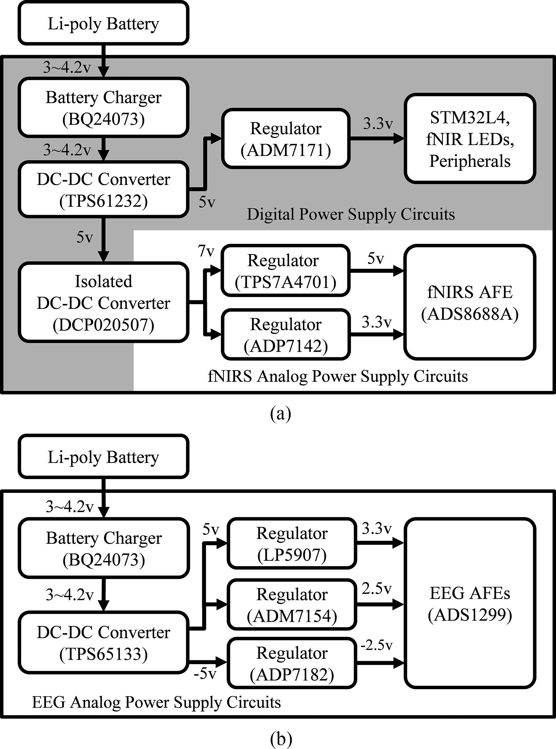
Schematics of power-supply circuit for (a) main board, and (b) slave board. Two lithium-polymer batteries supply power to the main board and the slave board, respectively. In the main board, the isolated DC–DC converter separates the ground planes for the main control cir- cuit (shaded digital power supply section) and the isolated NIRS acqui- sition circuit (fNIRS analog power supply section).
procedure, 8-channel bio-optical data can be finally obtained at a 5-SPS sampling rate. The following procedure was also used to perform EEG mea- surements on the slave board. The EEG measurements acquired by the dry electrodes are filtered by the onboard input filter stage.
X2Y type capacitors were employed in this filter stage to facilitate higher attenuation of electromagnetic and radio- frequency noise, while reducing onboard space requirements.
Inside the ADS1299 AFE IC, the filtered EEG measurements are amplified by a built-in low noise PGA with a 24 gain setting and digitized by a dedicated ADC for each channel over every sampling period (4 ms). The sampled EEG data are then trans- mitted to the microcontroller (MCU) via an SPI bus. With two ADS1299s in a daisy-chained configuration that allows multiple ICs to be controlled simultaneously using a single shared bus, 16-channel EEG measurements can be obtained at a 250-SPS sampling rate.
2) Power Supply Circuit: Fig. 2 depicts a schematic of the power-supply circuits of the proposed HBM system. The proposed system is powered by two lithium-polymer batteries—one each for the main and slave boards—which can be charged via the onboard battery management IC (Texas Instruments BQ24073) through a USB port. As the battery LEE et al.: DRY ELECTRODE-BASED FULLY ISOLATED EEG/FNIRS HYBRID BRAIN-MONITORING SYSTEM
1059
Fig. 3. Schematic of the MOSFET-based NIR LED driving circuit employed in the proposed HBM system. This circuit was combined with a DAC, analog multiplexer, and OPAMP-based buffering circuit to flexibly control the emission intensity of the four LEDs. By implementing two copies of this circuit, the proposed system can control up to eight LED emissions.
voltage decreases over time, boost and dual-output DC–DC converters (Texas Instruments TPS61232, TPS65133) are used to stabilize these output voltages. An isolated DC–DC converter (Texas Instruments DCP020507) is employed to supply fully isolated power for the fNIRS acquisition circuits on the main board. In the final stage of the power-supply circuits, low-noise DC voltage is lastly delivered to the AFE ICs, MCU, and other peripherals through six low-noise linear regulators (Analog
Devices—Adm7154, Adp7182, Adp 7142, And Adm7171;
Texas Instruments—TPS7A4701 and LP5907). 3) MOSFET-Based LED Driving Circuit: Fig. 3 illustrates the schematic of the MOSFET-based LED driving circuit. Be- cause the number of NIR light sources required may vary de- pending on the configuration of the probe set layout and the experimental paradigm, a programmable control function for multi-channel emission is required for the LED driving cir- cuitry. A calibration function for radiant intensity is also neces- sary because the NIR LED may exhibit radiant power mismatch even for the same current consumption. Thus, a programmable LED driving circuit was designed to flexibly control the radiant intensity of multi-channel NIR LEDs by combining a digital-to- analog converter (DAC), an analog multiplexer and MOSFET drivers. In operation, the MCU regulates the gate voltage of the MOSFET driver by controlling the output voltage of the built-in digital-to-analog converter (DAC) of the MCU. The regulated gate voltage is buffered with an OPAMP and then fed to the analog multiplexer (Analog Device ADG729) for con- trolling multi-LED emissions. The multiplexed gate voltage is lastly supplied to the N-channel MOSFET driver to modulate the LED current flow. This design provides flexibility to control as many as eight NIR LED emissions with fine-tuned radiant intensity in the proposed system. In the human subject studies described in this paper, the radiant intensity for all NIR LEDs was manually adjusted to 10 mW using an optical power meter and DAC output voltage control.
B. Sensors
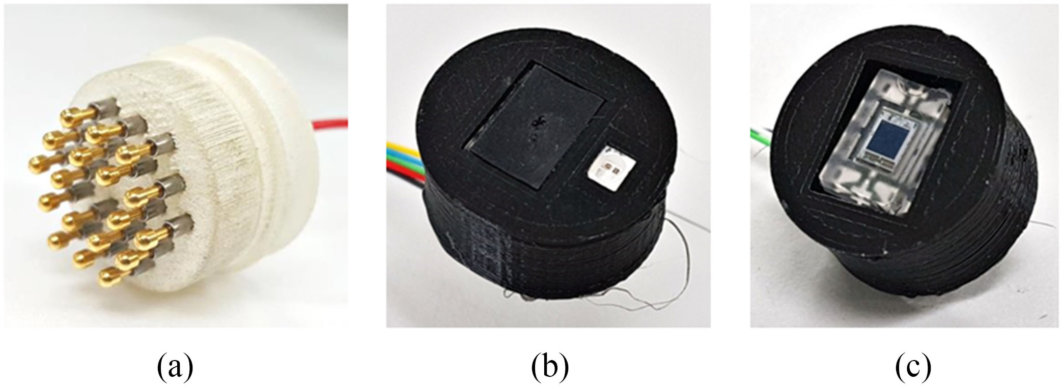
Customized sensor units were designed for the EEG and bio-optical measurements to enhance the usability and re- Fig. 4.
(a) Dry electrode for EEG measurement, (b) dual wavelength LED-based NIR light source unit, and (c) silicon photodiode-based NIR detector unit for bio-optical measurement.
configurability of the proposed system. The sensor units comprise 16-channel dry electrodes, 2-channel NIR LEDs, and 6-channel photodiodes.
Customizable
EEGCAP: The Fig. 4(a) depicts a prototype of the dry electrode for the EEG measurements, which comprises spring-loaded probes, a PCB, and a housing. The electrode unit, which is designed to remain in contact with the subject’s scalp, acquires EEG potentials via the 18 spring-loaded probes (Leeno Indus- trial Inc., SK100R). Each probe comprises four components— the (1) plunger, (2) barrel, (3) spring, and (4) probe receptacles.
The plunger is combined with a barrel and spring to consti- tute the spring-loaded structure. Each spring can withstand up to 54 g of pressure in its maximally compressed state. This enables each probe to maintain a suitable contact pressure on the uneven surface of the scalp. In terms of electrical specifi- cations, the resistance of each probe is less than 50 mΩ, which is sufficiently low for conducting bioelectrical measurements.
All probes are electrically connected to each other via the PCB embedded in the electrode housing and are thereby linked to a single electrode wire. The entire electrode assembly is enclosed by the 3D-printed plastic housing.
A helmet-like bracket (named the EEGCAP) was designed using flexible rubber materials to hold the dry electrodes in po- sition in accordance with 10–20 systems. The mesh-type EEG- CAP structure was equipped with as many as 58 holes to allow electrodes to be positioned on the scalp. Each electrode was
1060
Fig. 5. Installation layout of NIR LEDs (L1 and L2) and photodiodes (PD1–PD6) for acquisition of the bio-optical measurements. To investi- gate hemodynamic changes at the frontal lobes, the light source and detector units are attached using a transparent double-sided tape. This layout produces 8-channel hemodynamic responses from the 1-to-8 bio- optical channels marked in blue color.
firmly engaged in the hole via an interlocking frame structure, and able to continuously push against the subject’s scalp to maintain a constant pressure. This customizable structure could make a number of configuration choices available in terms of the electrode-positioning layout depending on the experimental paradigm.
2) NIR Light Source and Detector Units: Dual wavelength (730 and 850 nm) AlGaAs LEDs (Opto ENG OE-MV7385-P) were used for the NIR light source unit depicted in Fig. 4(b).
Two LEDs packaged in a miniaturized plastic leaded chip car- rier (PLCC) were soldered onto a light source PCB and covered by 3D printed materials. The spectral spread of the emitted ra- diation (Δλ = 30–40 nm) was broader compared to that of monochromatic laser diodes (Δλࣈ1 nm). However, the inco- herent and un-collimated characteristics of the LED light source achieve sufficient tissue penetration to enable the investigation of local hemodynamic changes. Owing to its suppressed heating and low risk of retinal damage, it can be used in direct contact with the human scalp .
The NIR detector unit depicted in Fig. 4(c) was based on a silicon photodiode device (Texas Instruments OPT101) inte- grated with an on-chip trans-impedance amplifier. Because the device exhibits high spectral sensitivity in the infrared spectrum (>0.5 A/W in the 730–850 nm wavelength), it is optimized for use in NIR detection applications. Owing to the built-in trans-impedance amplifier circuitry composed of an operational amplifier and an internal feedback network, the photodiodes pro- vide direct voltage output with a sufficiently wide bandwidth (14 kHz) which is linearly proportional to the detected light inten- sity. The photodiode is soldered onto a detector PCB along with decoupling capacitors, and housed inside a 3D-printed-casing.
Fig. 5 illustrates the positioning layout for NIR LEDs and photodiodes for placement on the subject’s forehead. The lay- out configuration occupies a 9 cm × 3 cm area with two NIR LEDs and six photodiodes, and the distance between the light source and the detector unit was set at 2.7 cm. In operations us- ing this layout, the NIR LEDs flicker alternately in accordance with the pre-programmed LED switching sequence and only the photodiodes surrounding the turned-on LED are instantaneously activated. Each hemodynamic response is measured in the area between the pair of light sources and the detector unit and this area is defined as a bio-optical channel. To achieve the maximum number of bio-optical channels in the restricted forehead space, measurements for bio-optical channels 3 through 6 located be- tween NIR LEDs L1 and L2 are all required. By exploiting a TDM-based channel-sharing scheme where one photodiode can provide multiple independent measurements in non-overlapped timing periods, the four independent measurements for these centrally located bio-optical channels can be provided from photodiodes PD3 and PD4; i.e., photodiode PD3 can provide measurements for the 3rd and 5th bio-optical channels and pho- todiode PD4 can provide measurements for the 4th and 6th optical channels in the same manner. Therefore, this channel sharing operation enables the proposed sensor layout to acquire 8-channel bio-optical measurements with only six photodiodes.
C. System Operation And Hybrid Data Acquisition
The ADC basically converts analog input signals into digi- tized signals with consistent intervals based on an internal or external reference clock. However, the clock may have its own tolerance and frequency drift characteristics. In heterogeneous data-acquisition systems employing two or more ADCs to pro- duce a fully synchronized data stream, the clock tolerance of individual ADCs makes accurate synchronization difficult to achieve. This problem can be solved by using a reference sys- tem clock to which all ADCs could be universally referred.
Complete synchronization is achieved between the EEG and bio-optical measurements by using the data-ready signals (re- ferred to as DRDY in the datasheet) generated by the ADS1299 AFE IC as the reference system clock. The DRDY signal rep- resents the transition of a falling edge when the digitized EEG data stream becomes valid. It, therefore, generates a pulse signal of the same period as the sampling rate of EEG acquisition. By synchronizing the emission control of NIR LEDs and data acqui- sition of ADS8688A with the DRDY pulse cycle, the complete synchronization between EEG and bio-optical measurements can be preserved regardless of the occurrence of small timing errors in the reference clock of each AFE.
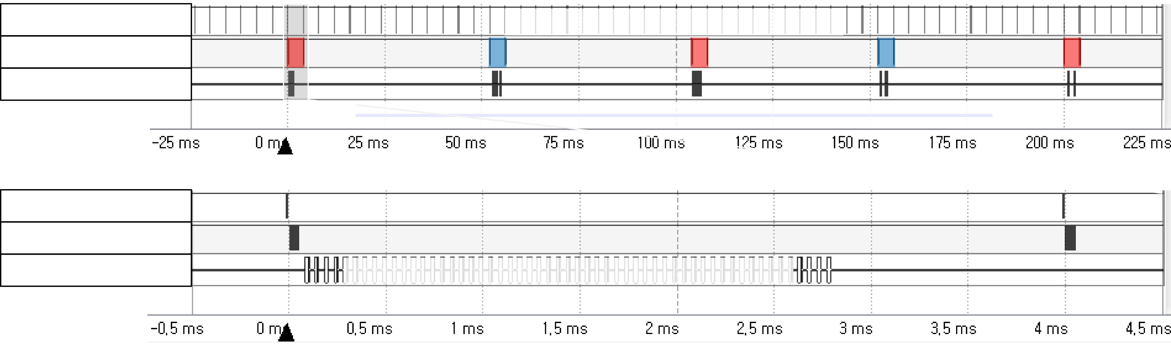
Fig. 6 depicts a single period of simultaneous EEG and bio- optical acquisition captured from the logic analyzer screen. Once ADS1299 begins to acquire EEG measurements at a pre- programmed sampling rate (250 SPS), the DRDY pulses begin to be generated with the same sampling period (4 ms) as EEG data generation. In accordance with the generation of the DRDY pulse, NIR radiation of dual wavelengths (730 and 850 nm) is al- ternately switched in the order—L1 (730 nm)–L2 (730 nm)–L1 (850 nm)–L2 (850 nm)—over the course of 50 EEG acquisition cycles (200 ms). Each time the NIR LED is turned on by the mul- tiplexer switching, the radiation lasts for 4 ms, during which time the ADS8688A acquires NIR light intensities from the set of ac- tivated photodiodes surrounding the turned-on LED; i.e., when the L1–730 nm or L1–850 nm states are active, measurements from the photodiodes PD1–PD4 are sampled. This also applies to the two L2 states and sampling of photodiodes PD3–PD6. To LEE et al.: DRY ELECTRODE-BASED FULLY ISOLATED EEG/FNIRS HYBRID BRAIN-MONITORING SYSTEM
1061
Fig. 6. Logic analyzer view of one period of simultaneous EEG and NIRS acquisition and magnified view of the upper gray region (−0.5–4.5 ms). According to the DRDY pulse generated by the ADS1299, 16-channel EEG measurements are acquired, and the NIR light sources L1 and L2 are alternately activated for 4 ms. During NIR irradiation for 4 ms, each of the 4-channel photodiodes surrounding the light source measured the light intensity 14 times and averaged it. A total of 16-channel of bio-optical measurements are obtained over a 200-ms period, which is converted into 8-channels of fNIRS data during the fNIRS decoding process.
obtain stable measurements with minimized background noise, the light intensity measurement of each bio-optical channel is repeatedly acquired 14 times with a 50–μs interval and subse- quently averaged. During the 4-ms period of LED radiation, a total of 56 optical measurements are then sequentially obtained within 2.8 ms from the four photodiodes surrounding the turned- on LED. While the four LEDs are flashing sequentially within a 200-ms period, a total of 16 bio-optical measurements can be obtained through a time-division multiplexing operation.
The aforementioned sequence allows fully synchronized 16-channel EEG and 16-channel bio-optical measurements to be acquired every 4 ms ( = 250 SPS) and 200 ms ( = 5 SPS), re- spectively. The acquired measurements are then packetized and successively transmitted to the host device via the SPBT3.0 DP2 Bluetooth module (STMicroelectronics, USA) with a header and timing information. The host device decodes the packets of EEG and bio-optical data using MATLAB 2014a (MathWorks, USA). Using the Modified Beer-Lambert Law , in the decoding process, the 8-channel fNIRS data, including concen- tration changes in the oxy- (ΔHbO), deoxy- (ΔHbR), and total hemoglobin (ΔHbT), are also converted from the 16-channel bio-optical data.
The MCU system was programmed to perform the following
Operations:
1) Peripheral initialization—establishment of peripheral in- terfaces (SPI interface, general purpose input/output ports, and interrupt routine) and setting up registers of
All Afe Ics;
2) Launching the data-retrieval loop upon detection of the
Start Trigger;
3) Acquisition of EEG data from ADS1299, when a DRDY
Pulse Is Generated;
4) Control of NIR LED emission in accordance with the
Led Switching Schedule And Drdy Trigger;
5) Acquisition of bio-optical data of the predefined photo- diode sets from ADS8688A in accordance with the LED
Control Sequence;
6) Packetization of acquired EEG and bio-optical data along with header and timing indication and subsequent transmission of data packets to the host device via the
Bluetooth Module;
7) Repeating steps 3 through 6 until the stop trigger is detected.
A. Evaluation Of Eeg And Fnirs Acquisition
1) EEG Phantom Experiment using Dry Electrodes: The proposed HBM system employs dry electrodes for EEG ac- quisition instead of the conventional wet electrodes for wide applicability and enhanced usability. Therefore, it is necessary to verify the acquisition capability of the dry electrodes at the level of micro-voltage amplitudes. In the proposed system, the fNIRS and EEG acquisition circuits operate simultaneously.
Thus, EEG signal acquisition is subjected to interference from the electrical switching noise generated by the NIR LEDs and this effect must be examined. For this purpose, we devised an EEG phantom experiment.
First, EEG-like voltage signals were generated. Raw EEG data samples of 60-s duration were taken from the C3 channel of a BCI competition 3-IVa dataset (motor imagery task, down- sampled to 250 Hz) . These EEG data samples were then inputted to an arbitrary waveform generator (Keysight 33220A) for reproduction of a EEG voltage waveform. The reproduced voltage waveform was then passed through a voltage divider circuit (of 10000:1 ratio) to create a microvolt-level EEG signal.
This voltage waveform was finally fed to the EEG phantom. Second, an EEG phantom was created using a conductive rubber pad (10 cm × 12 cm × 5 mm, 100 Ω/cm) to simulate a real human scalp. An NIR LED unit is placed at the center of the rubber pad. Then, one dry and one wet electrode (with conduc- tive gel) were attached around the LED unit on the rubber pad to emulate the NIR interference during EEG signal measurement.
The two electrodes and the NIR LED unit were connected the EEG input port and NIR LED driving port of the HBM, re- spectively. The EEG reference input of the HBM system was connected to the ground potential of the waveform generator.
Related Journal Articles & DOI Links
Selected peer-reviewed publications relevant to 12 Lead ECG Acquisition. Click the DOI to access the full paper (may require institutional access).
-
1. Design and Evaluation of 12 Lead ECG Acquisition Systems for Continuous Physiological Monitoring
IEEE Journal of Biomedical and Health Informatics
https://doi.org/10.1109/JBHI.2020.2981234 -
2. Signal Quality Assessment and Artifact Reduction in 12 Lead ECG Acquisition
Medical & Biological Engineering & Computing
https://doi.org/10.1007/s11517-020-02145-6 -
3. Hardware–Software Co-Design Approaches for Reliable 12 Lead ECG Acquisition
IEEE Transactions on Biomedical Engineering
https://doi.org/10.1109/TBME.2019.2895762 -
4. Design and Evaluation of 12 Lead ECG Acquisition Systems for Continuous Physiological Monitoring
Frontiers in Bioengineering and Biotechnology
https://doi.org/10.3389/fbioe.2020.00123 -
5. Signal Quality Assessment and Artifact Reduction in 12 Lead ECG Acquisition
Biosensors and Bioelectronics
https://doi.org/10.1016/j.bios.2021.112345 -
6. Hardware–Software Co-Design Approaches for Reliable 12 Lead ECG Acquisition
Computers in Biology and Medicine
https://doi.org/10.1016/j.compbiomed.2021.104567 -
7. Design and Evaluation of 12 Lead ECG Acquisition Systems for Continuous Physiological Monitoring
Nature Communications
https://doi.org/10.1038/s41467-020-12345-6
Why Choose Us?
Bangalore guidance for robotics, Spectre and autonomous systems projects.
Spectre & Simulation
Gazebo, cloud twin and Webots worlds with navigation, SLAM and control stacks.
Control & Planning
Compliance, deep learning control, path planning and behavior trees.
Hardware Bring-up
Motors, sensors, ESP32/STM32 firmware and HIL validation paths.
Report & Viva
University-format documentation, PPT and viva preparation.
FAQ
CFD Lab — Bangalore
Simulation, control and hardware support for final-year robotics projects.
Stacks
Worlds
Digital Twin
Control
Robots
Offline
Bring-up