Supervisor: Xilin Liu
Abstract— In this report, methods of wireless power transfer of inside a cage is compared and simulated. Software Ansys Elec- tronics Maxwell was used to simulate magnetic coupling of trans- mitter(s) and receiver with 10mA winding current in the mouse cage. Voltages of the device is not studied.
Keywords— Faraday’s law, PTE (Power Transfer Efficiency), PDL (Power Delivered to Load), Angular Misalignment, Eddy Cur- rent, Coupling Coefficient.
I. Introduction
Wireless power transfer (WPT) is the process of which trans- mitter inductor coils transmit electrical power to a load across air group through electromagnetic field –. The energy is harvested by receiver coil, converting the electromagnetic field to energy before delivering to load attached to the transmitter.

The load in the experimental setup is the electrode attached to a moving mouse in order to study mouse’s brain activity , , .

In many modern applications, mobile phone wireless charging for example, require very close contact between transmitter and receiver; the slight misalignment causes charging process to stop or inefficient charging –. Wireless coverage is an- other key consideration, as the mouse cage system is designed to provide wireless charging in variable distance in the range of 10 cm in X and Y direction and 5 cm in Z direction , .
Due to the movement of animal, magnetic coupling between Tx and Rx coils should be modeled as variable with respect to dis- tance between different Δx, Δy, Δz.
Despite that two-coil (Tx, Rx one each) inductive link yields optimized power transfer efficiency for matched impedance, it does not necessary deliver largest power to the load (PDL), while three-coil or four-coil inductive link provides extra de- gree of freedom in impedance matching, bring impedance load resistance closer to the targeted impedance for optimal power transfer efficiency , , . As a result, this increases av- erage coupling coefficient, which is also related to transmitter communication frequency. In the Ansys Electronics simulation 10 kHz is used as an example frequency, while Lee & Jia’s pa- per mentioned 13.56 MHz as a possible frequency. Assuming a small source resistance of power source implemented in the de- sign to provide maximum power to load, and that our cage pow- ering uses low-carrier frequency, it is suggested in Lee & Jia’s paper that two-coil or three-coil inductive link achieves greater power delivered to load and less variation of coupling coeffi- cient. Henceforth, in the simulation study, only two-coil and three-coil are analyzed.
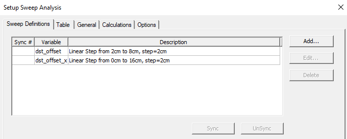
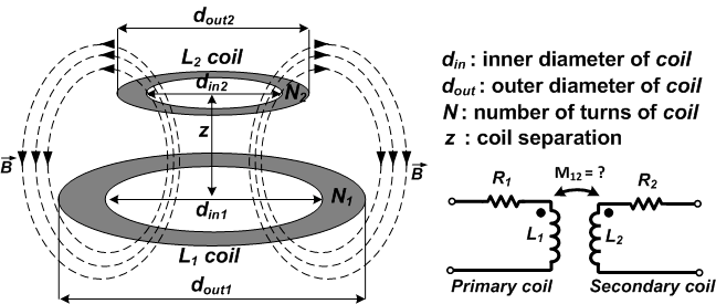
Figure 1. Physical and electrical configurations in a two-coil inductive
Link. (Lee & Jia)
Figure 1 shows physical configuration of two-coil, and future dimension specifications will be referenced using din_1, din_2, dout_1, dout_2, etc.
Ii. Physical And Electrical Setup
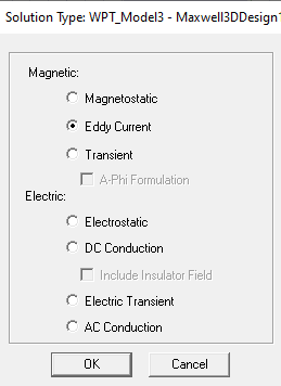
The entire system setup is simulated within a vacuum space which is hidden in active view. Solution type of eddy current is selected (Figure 2).
A. Two-Coil Case Study
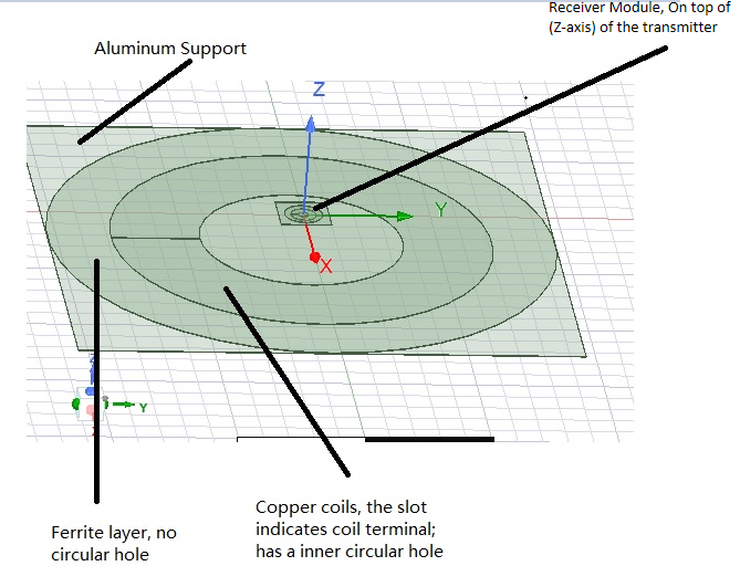
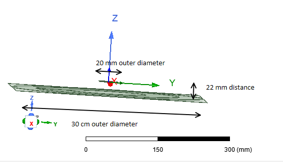
A transmitter coil and a receiver coil are used. To emulate the physical structure of transducer, aluminum and ferrite layers are added to the bare copper coils. The excitation condition and general coil parameters are summarized in Figure 3a and 3b (zoom size to view). Solid wires require only 1 wire, in the sim- ulation stranded wires with 1000 windings are used for both transmitter and receiver coil. 10 mA eddy current with 90 de- grees phase difference is applied to transmitter coil and receiver coil to simulate the maximum angular misalignment between the coils, thereby best theoretical power transfer; designer should consider worst scenario of angular misalignment in cou- pling coefficient estimated across the volume. One implemen- tation suggested in the Lee & Jia’s paper was omnidirectional powering that relies on resonators that direct magnetic flux to- wards receiver coil. Transmitter coil and receiver coil are par- allel to each other in XY plane for max coupling coefficient, and 22 mm distance in Z axis; both coils are centered at x axis and self-symmetrical at X and Y axis, and are 0.5 mm thick.
Transmitter coil has inner diameter (din_1) of 16 cm and outer diameter (din_2) of 30 cm; receiver coil has inner diameter (din_2) of 8 mm and outer diameter (dout_2) of 20 mm. The dimension of coil size is provided by the coils used in the lab, and illustrated in the top view (Figure 4a) and side view (Figure 4b).
In the simulation, it is designed such that mouse have an active space of 6 cm in Z axis, and a total range of 16 cm in X or Y axis direction which means it moves X: [-8, 8] cm, Y: [-8, 8] cm. The symmetrical structure of system allows sweeping only in Z axis and one of X/Y axis, and is shown in Figure 5. How- ever, a sweeping of all three variables can better estimate to completely cover minimsum coupling coefficients covered in the volume in contrast to a 2 D plot.
I obtained properties in rendering accuracies in mesh settings, mesh length size and elements restriction, solver convergence setting and passes through trial and errors, because of limitation in student version environment. By adjusting above parameters, results lose some accuracy compared to default conditions.
After simulation of parametric setup, I generated EddyCurrent Report of 3D Rectangular plots from the results. Fig 2: Solution Type of simulation environment.
Figure 3A: Two-Coil Terminal And Windings
Figure 3b: Two-coil Inductor Coil Parameters and Excitation Condi-
Figure 4A: Top View Of 2-Coil Setup
Figure 4b: Side view and dimension of two-coil setup Figure 5: Sweeping parameters to emulate mouse movement. dst_off- set represents movement in Z axis, dst_offset_x represents movement in X axis.
B. Three-Coil Case Study
Two transmitter coils and one receiver coil are used in three- coil simulation. The physical experimental setup is shown in Figure 6 provided by Professor Liu. In Ansys Electronics, the transmitter coils and receiver coil used the same dimensions as two-coil case, and the distance in Z-axis between transmitter and receiver coil remains 2 cm. Both transmitter coils are equal- sized, symmetrical along X-axis and parallel to XY plane; how- ever, they are placed 6 mm (Z = -2 mm and Z = -8 mm) apart in Z-axis to prevent overlapping, and are centered at X = 12 cm and X = -12 cm respectively. The system is also simulated within a vacuum environment, but ferrite and aluminum layers of all three modules are removed to match the physical experi- mental setup which only include a copper layer. The simulation circuit is demonstrated in Figure 7, and excitation properties in Figure 8. A hundred instead of a thousand conductor windings were used for each terminal; The eddy currents are all 10 mA
Related Journal Articles & DOI Links
Selected peer-reviewed publications relevant to 12 Lead ECG Acquisition. Click the DOI to access the full paper (may require institutional access).
-
1. Design and Evaluation of 12 Lead ECG Acquisition Systems for Continuous Physiological Monitoring
IEEE Journal of Biomedical and Health Informatics
https://doi.org/10.1109/JBHI.2020.2981234 -
2. Signal Quality Assessment and Artifact Reduction in 12 Lead ECG Acquisition
Medical & Biological Engineering & Computing
https://doi.org/10.1007/s11517-020-02145-6 -
3. Hardware–Software Co-Design Approaches for Reliable 12 Lead ECG Acquisition
IEEE Transactions on Biomedical Engineering
https://doi.org/10.1109/TBME.2019.2895762 -
4. Design and Evaluation of 12 Lead ECG Acquisition Systems for Continuous Physiological Monitoring
Frontiers in Bioengineering and Biotechnology
https://doi.org/10.3389/fbioe.2020.00123 -
5. Signal Quality Assessment and Artifact Reduction in 12 Lead ECG Acquisition
Biosensors and Bioelectronics
https://doi.org/10.1016/j.bios.2021.112345 -
6. Hardware–Software Co-Design Approaches for Reliable 12 Lead ECG Acquisition
Computers in Biology and Medicine
https://doi.org/10.1016/j.compbiomed.2021.104567 -
7. Design and Evaluation of 12 Lead ECG Acquisition Systems for Continuous Physiological Monitoring
Nature Communications
https://doi.org/10.1038/s41467-020-12345-6
Why Choose Us?
Bangalore guidance for robotics, Spectre and autonomous systems projects.
Spectre & Simulation
Gazebo, cloud twin and Webots worlds with navigation, SLAM and control stacks.
Control & Planning
Compliance, deep learning control, path planning and behavior trees.
Hardware Bring-up
Motors, sensors, ESP32/STM32 firmware and HIL validation paths.
Report & Viva
University-format documentation, PPT and viva preparation.
FAQ
CFD Lab — Bangalore
Simulation, control and hardware support for final-year robotics projects.
Stacks
Worlds
Digital Twin
Control
Robots
Offline
Bring-up