Dhrubo Ahmad
1, Jakob Bakall1, David Clausen1, Jerry Anderson1, Roberto Peralta1, Kirtana Sandepudi3, Alex Benedetto4, Ethan Yang2, Diya Basrai2,
1,7,8
Electrical stimulation of the neuromuscular system holds promise for both scientific and therapeutic biomedical applications. Supplying and maintaining the power necessary to drive stimulation chronically is a fundamental chal- lenge in these applications, especially when high voltages or currents are required. Wireless systems, in which energy is supplied through near field power transfer, could eliminate complications caused by battery packs or external connections, but currently do not provide the harvested power and voltages required for applications such as muscle stimulation. Here, we introduce a passive resonator optimized power transfer design that over- comes these limitations, enabling voltage compliances of ± 20 V and power over 300 mW at device volumes of 0.2 cm2, thereby improving power transfer 500% over previous systems. We show that this improved performance enables multichannel, biphasic, current-controlled operation at clinically relevant voltage and current ranges with digital control and telemetry in freely behaving animals. Preliminary chronic results indicate that implanted devices remain operational over 6 weeks in both intact and spinal cord injured rats and are capable of producing fine control of spinal and muscle stimulation.

Electrical stimulation of the central and peripheral nervous system is a highly successful approach for treating a wide range of clinical dis- orders in humans, such as restoration of hearing1, electroanalgesia2, or suppression of motor disorders such as Parkinson’s3. These approaches often use electrical stimulation to either replace lost electrical neural signals, as in cochlear implants, or to interrupt dysfunctional neural circuits, as in deep brain stimulation. However, there is a growing appreciation for potential applications using electrical stimulation not only to restore lost function, but also to retrain or rehabilitate residual
Or
neuromodulation4–6. The promise of such approaches is that a transient intervention involving continuous targeted electrical modulation might induce changes in neural function that accelerate rehabilitation6,7 or even deliver outcomes not possible with current approaches.

One fundamental challenge in these applications is supplying and maintaining the power necessary to source the currents and voltages
1234567890():,;
1234567890():,;
required to achieve therapeutic outcomes, especially in applications involving large currents and voltages over extended time periods. Many human applications use large batteries that must be periodically recharged or replaced, which can create barriers to adoption by patients8. In preclinical experiments in small animals such as rats and mice, this challenge is even more critical, since battery size is limited and frequent battery replacement will interfere with animals’ behavior.
Alternatively, power can be supplied in small animals through external cabled connections, but this approach increases risk of infection, causes the formation of scar tissue9, can displace implanted electrodes10, limits physical activities11 and is incompatible with mag- netic resonance imaging12,13. The use of either batteries or wired con- nections, therefore, makes it difficult to evaluate neuromodulation or rehabilitation strategies involving continuous, uninterrupted stimula- tion protocols lasting multiple days or weeks.
Wireless systems, in which stimulation energy is supplied through near-field power transfer, have the potential to overcome these lim- itations, enabling chronic applications without the need for batteries or external connections. However, the amount of power that can currently be harvested in these systems is limited, since the maximum power point voltage (i.e. the voltage at which most power can be harvested) depends on the inductance ratio and coupling between transmitter and receiver antennas14. This dependence results in a tra- deoff between the operational voltage of a device and its power har- vesting ability, making it difficult to engineer systems that can supply voltages and power in the desired range. There is therefore a critical need for technologies that can increase the amount of transferred power at the desired operational voltage suitable for chronic func- tional electrical stimulation.
There are additional challenges in applications for functional electrical stimulation using chronically implanted devices. Standard fabrication approaches for neural interface devices typically result in stiff, inflexible devices which limit body motion or cause discomfort which can affect functional outcomes15. The recent development of thin flexible circuits and soft, bio-compatible materials allows the fabrication of conformable interfaces for placement within the central and peripheral nervous systems. Importantly, this class of devices can also be powered and controlled wirelessly for fully implanted systems16–19. These flexible devices can be nearly imperceptible to the host due to the reduced micromotions minimizing tissue irritation15,20 and their increased bio-compatibility enables longer functional life- times, making them suitable for long-term applications.
Applications
involve complex stimulation protocols, delivered across multiple locations in the central and peripheral nervous system in precise temporal relationships and with highly regulated stimulation levels.
Current battery-free systems typically use passive, unregulated voltage control21 or relatively simple voltage programming16,22,23. Existing devices capable of delivering controlled currents with precise and versatile programming require application-specific integrated circuits (ASICs) that are expensive and do not provide a general platform that can be used across a wide range of applications24.
Additional challenges arise in applications targeting multiple areas that require very different currents or voltages; depending on the density of cell bodies and axons surrounding a stimulation elec- trode, the distance between cells and electrode as well as the electrical interface, required currents can widely vary25,26. For example, in the case of intraspinal stimulation, where the electrode is situated near many neurons and axons, functional currents can range from 0.5 µA27 to 15 µA28. Epidural spinal stimulation electrodes, which contact fewer cells than intraspinal stimulation but still contact a relatively high density of fibers, use current amplitudes typically ranging from 50 to 500 µA29–31. Muscle stimulation electrodes, which may contact and recruit even fewer highly branched axons, can require currents up to 4.5 mA in rats32–34. Furthermore, electrode impedances and their current amplitudes may require voltages from a few mV to tens of volts16,28,31. Devices are typically capable of delivering either low or high ranges of currents/voltages, but not both ranges simultaneously that allow for simultaneous electrical stimulation of multiple neuromus- cular sites and for multichannel abilities.
Here, we introduce fully implanted devices that overcome these challenges, providing a voltage range of up to ±20 V, current- controlled stimulation with a range of 40 μA to 4.7 mA, and indepen- dent control of 8 channels in a fully implantable package that is pow- ered at distance. This device represents the highest figure of merit for all categories (Supplementary Table 1)23,24,35–41, making it suitable for long term, uninterrupted functional electrical applications for pre- clinical investigations in freely moving small to medium animal sub- jects. The devices exploit a passive resonator scheme that substantially increases power harvesting capabilities at a designed voltage, making it possible to stimulate multiple areas of the nervous system simulta- neously, using the same implanted device. The circuit design incor- porates off-the-shelf components providing scalable manufacturing at a cost that enables single-use deployment which is critical for chronic implantation that make reuse impossible or difficult. The devices are fully implanted, powered and controlled wirelessly, and are fabricated from flexible electronics. The materials and mechanical design of the flexible substrate provides a platform that integrates components to conform with the surrounding soft tissue using a network of ridged islands and flexible interconnects. As a consequence, the devices have minimal impact on overall animal behavior and can remain operational for extended periods of at least 6 weeks. Further, the devices are able to deliver highly versatile, precisely controlled, and charge-balanced stimulation and are designed for scalable manufacturing that enables easily deployable one-time-use systems to deliver long-term stimula- tion. Taken together, these advances in device performance enable the development and evaluation of a range of complex chronic stimulation protocols for functional restoration that have previously been unat- tainable. We demonstrate the capabilities of this device in one bio- medical application: electrical stimulation of the spinal cord and muscles in freely behaving and spinal cord injured rats, showing that this device is capable of producing functional limb movements from spinal and muscle stimulation for over 6 weeks indicating good chronic stability and laying the foundation for further validation studies.
Wireless Fes Device Overview
In this work, wireless, battery-free designs and a monolithic device structure, are leveraged to create a soft, biocompatible, flexible device class that can be fully implanted in highly mobile areas of a rat, such as the back and hind leg. The systems offer a platform to deliver effective stimulation in freely moving subjects without affecting mobility or behavior, making them suitable for chronic experimental research.
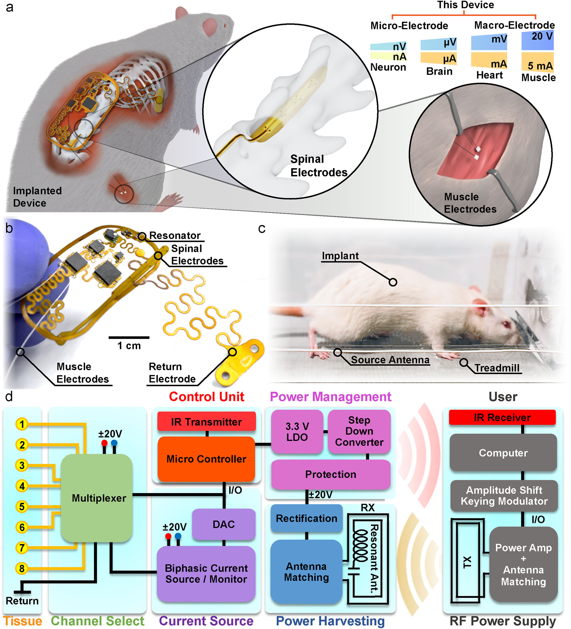
The system has immediate application to neuroprosthetics and neu- romodulation therapies relevant to a wide range of clinical applica- tions, including spinal cord injury (SCI). Figure 1a displays a rendering of a device implanted subcutaneously in the posterior lumbar region of a rat. The device has the capability for both spinal and muscular functional electrical stimulation (FES) using an eight-channel electrode arraypositioned over the spinal cord and two intramuscular electrodes in the biceps femoris posterior (Fig. 1a). This device can accommodate electrode designs for µA to mA of stimulation using both micro- electrodes ( < 200 µm) for precise stimulation of a group of neurons and macro-electrodes ( > 200 µm) for intramuscular stimulation. This multimodal stimulation capability enables a wide range of strategies for using electrical stimulation for the restoration or rehabilitation of motor function. We use a monopolar configuration with a common return electrode placed in the thorax, as is common in rehabilitation applications42. In order to maximize the mechanical flexibility of the
2
device and enable chronic stability, the integrated circuits (IC) in the device are placed in separate rigid islands and interconnected with strain-isolating serpentine traces43,44 (Fig. 1b; Supplementary Fig. 1; see detailed component description in Supplementary Fig. 2a, b). Self- similar serpentines utilize a fractal design with repetitive patterning of interconnected curvatures that evenly distribute internal strain within the flexible substrate. We utilize this patterning structure to connect the device body to the spinal electrodes and the return electrode, to improve strain isolation, to facilitate easy implantation of the elec- trodes, and to improve device lifetimes14,18. The 20 mm × 40 mm device platform consists of a monolithic, dual-sided, flexible circuit board (height: 100 µm) composed of two rolled annealed copper layers separated by a polyimide film, enabling scalable manufacturing with off-the-shelf components. This fully implanted, battery-free design, with its flexible mechanics and low displacement volume (0.2 cm3), minimizes the impact of the implanted device on animal appearance, spontaneous exploratory activity levels, and locomotor kinematics.
These features enable free-running experiments with continuous, modulated stimulation for therapeutic treatments, such as FES reha- bilitation during treadmill locomotion in animals with SCI (Fig. 1c).
Fig. 1 | Wireless battery-free functional electrical stimulation overview. a Rendering of implant in the small animal subject with rendered insets of electrode placement in the spinal cord and muscle. b Photograph image of the device.
c Photograph of the animal running on a treadmill. d Block diagram of electrical functionalities of the device.
3
The operating principle of the device, as shown in Fig. 1d, includes a system that delivers continuous wireless power to the implant using an instrumentalized cage and communicates using a custom ampli- tude shift keying (ASK) modulation of the radio frequency (RF) power.
In order to improve power harvesting efficiency at the voltages necessary for peripheral stimulation, the device features a co-planar antenna that combines a passive resonator and receiver, using con- cepts from strongly coupled magnetic resonant systems to improve coupling and lower voltage of the maximum power point45–48. This design dramatically increases usable delivered power to the device, enabling dual voltage supplies up to ±20 V to drive stable biphasic currents over a wide range of electrode designs.
The dualvoltage supply is achieved using a center-tapped antenna design with two single half-bridge rectifiers to create the positive and negative voltages with no external components and only minimally increased device footprint. The receiver antenna uses a center-tapped antenna to minimize circuit complexity while allowing for dual voltage supplies. A dual supply coupled with a precision current driver allows for a small circuit design (30 mm2) suitable for implantation while providing higher power efficiencies compared to designs using DC/DC converters to generate dual voltage supplies49. This is significantly smaller than traditional systems using a single supply to have the same biphasic stimulation response using a Howland current pump, H- bridge, and current monitor each requiring additional electrical traces and passive components ( > 50 mm2)50–52. A power management sys- tem incorporates voltage protection using Zener diodes and a step- down converter accompanied by a linear voltage regulator for stable operating voltages for the digital circuit. The low-power micro- controller allows the device to be programmed through ASK mod- ulation without additional hardware and with minimal additional power consumption by schemes developed in our previous work16 utilizing internal electrically erasable programmable read-only mem- ory (EEPROM). The microcontroller uses a serial interface to commu- nicate with an 8-bit digital-to-analog converter (DAC) and multiplexer in order to control stimulation parameters. This design enables the specification of arbitrary stimulation patterns, distributed across multiple channels, and at a wide range of currents and voltages.
Information about real-time device performance is digitally trans- mitted transdermally through infrared (IR) communication17. Infor- mation on supply voltage and voltage applied to the electrode can be used to evaluate fault conditions (electrode shorts or disconnects, device failure), and to ensure accurate delivery of desired stimulation.
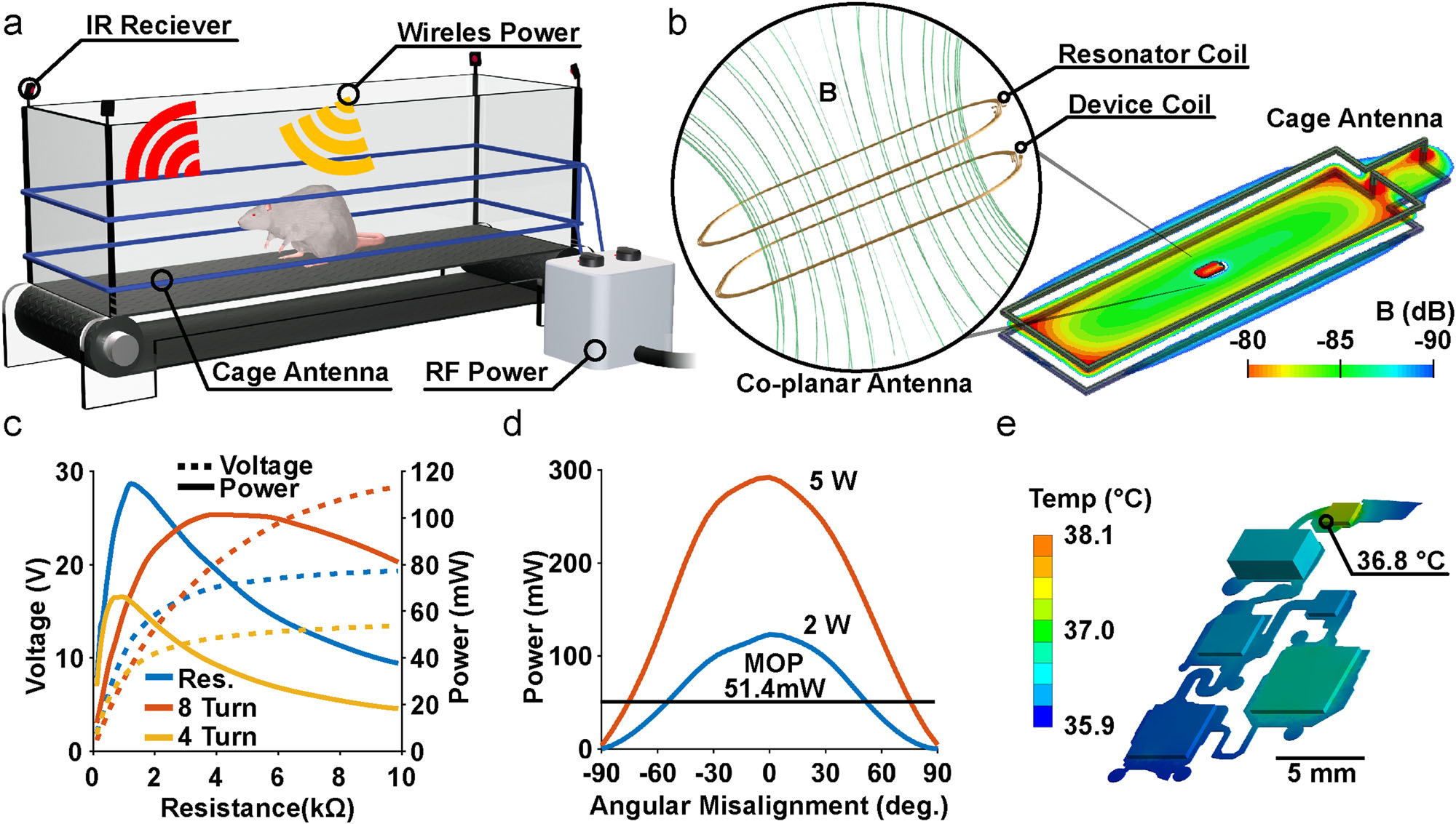
Additionally, electrode impedances can be computed for the evalua- tion of stability in chronic applications. Resonant antenna design and electrical characterization Wireless, battery-free platforms capable of delivering a wide range of currents and with high voltage compliances are critical for stimulation applications involving different excitable tissues. In the case of multi- modal FES, for example, currents and voltages can vary by orders of magnitude when activating peripheral nerve, epidural spinal cord, or intramuscular electrodes. Although high voltage compliances are necessary for these applications, they are challenging for traditional 2-antenna near field systems, since their operational voltage depends on the inductance ratio and coupling between transmitter and co- planar antennas which is limited, especially for small animals. In order to overcome these challenges, we introduce a design that imbeds a passive resonator directly on the implanted device, improving power transfer efficiency and enabling high voltage compliances. The monolithic integration removes the need for auxiliary circuit compo- nents such as resonators that are located elsewhere in the tissue. This design can also be easily implanted, enabling it to be used as a scalable platform for chronic applications. This design also requires only a small number of passive components, resulting in small device foot- prints and high efficiencies compared to active approaches such as maximum powerpoint tracking and management ICs. The device is optimized to operate in a treadmill enclosure (56 cm × 16 cm) with a 2-turn transmitter antenna with 4 cm spacing between the turns, and is optimized to match the range of vertical positions of the implanted device during normal behavior (Supplementary Fig. 3). Effective power transfer can be also be achieved with other transmitter antenna designs, for example using circular antennas in surgical settings during device implantation (Supplementary Fig. 4a–c)14,18. Figure 2a shows both the antenna setup used for wireless power transfer (WPT) and IR receivers located on the corners of the cage used to collect telemetry data from the implanted devices17.
The benefits of using a resonant 3-antenna system, with passive resonator co-located on the implanted device, over the conventional 2-antenna system are coupling enhancement, better misalignment insensitivity and better bandwidth53,54. Figure 2b and Supplementary Fig. 5a, b illustrate the simulated B-field of the 3-antenna system, in which the receiver antenna and the resonator are co-located on the top and bottom sides of the implant. The geometric parameters of the implant antenna (i.e., the width, the gap between adjacent turns, the dimension and shape of the antennas) are chosen to optimize trans- mission efficiency at 13.56 MHz (Supplementary Fig. 6a, b) while minimizing the size of the implant. Adding a resonator improves the coupling between the transmitter and receiver as shown in simulations (Supplementary Fig. 7a)54–57. A comparison between the transmission efficiency of the 3-antenna WPT and the conventional 2-antenna WPT shows that adding the resonator antenna increases the transmission efficiency from 12% to 37% (Supplementary Fig. 7b). Although similar transmission efficiencies can be achieved in traditional 2-antenna systems by increasing the number of turns in the receiving antenna (e.g., using 8-turns increases transmission efficiency to 30%) the higher inductance caused by the increased turns substantially increases the voltage at the maximum power point, as shown in Fig. 2c. Such high voltages are not practical in most highly miniaturized designs. It is therefore difficult in traditional 2-antenna designs to increase power transfer efficiency while maintaining desired voltage levels.
Providing continuous power delivery is challenging for explora- tory research in the large arenas necessary for complex behavioral testing or for evaluating behavior in larger animal models58. By increasing the efficiency of power casting, our design enables effective device performance over large areas, such as typical rat treadmill enclosures or home cages. The spatial distribution of harvested power within the treadmill enclosure exhibits a minimum of 120 mW in the center of the enclosure with maximum voltage compliance of ±20 V using a 2 kΩ resistor to match the operational load of the system during continuous operation while supplying the transmitter antenna 2 W of RF power (Supplementary Fig. 7c). The ability of this design to operate with low RF power makes setups substantially more energy efficient, a feature that is especially important for chronic applications.
If needed, power at the implant can be increased by increasing RF power of the transmitter up to a maximum safe specific absorption rate of <20 mW kg−1, which corresponds to an RF output power greater than the capabilities of the power amplifier (max 12 W) used in this work58. By increasing RF power to 6 W, up to 325 mW of power can be harvested in the center of the enclosure (Supplementary Fig. 7d), which is 5 times greater than the power consumption of comparable devices in the literature, providing a large operational margin to enable continuous and uninterrupted stimulation59. As a comparison, recently reported devices using a smaller transmitter antenna
Antenna
(3.5 cm × 2.5 cm; 8.75 cm2) were able to harvest 50 mW using 4 W of RF power in the transmitter59. The device described here uses a larger transmitter antenna (56 cm × 16 cm; 896 cm2) and similar receiver (4 cm × 2 cm; 8 cm2) as compared to receivers used in a previous work59 (3.5 cm × 2.5 cm; 8.75 cm2), however, this device is capable of har- vesting 250 mW using 4 W of RF power in comparison to 50 mW at 4 W
4
of RF power in that previous study59. This is an increase of more than 500% harvested power over previous designs (5.71 mW cm−2 to 31.25 mW cm−2), enabling effective power harvesting in large arenas59.
This performance is enabled by monolithically integrated passive resonator WPT introduced here that boosts power harvesting effi- ciencies with no increase to device footprint, requiring only an addi- tional copper layer for the resonant antenna. This extraordinary harvesting capability allows for more sophisticated behavioral para- digms in complex 3-dimensional behavioral arenas, such as elevated, or even submerged, mazes8,29. The increased power harvesting cap- ability also improves operational device stability during behaviors such as rearing, climbing, and preening, which often result in mis- alignment between antennae and a reduction of harvested power. The behavior that causes the greatest misalignment is rearing which represents 1% of total behavior time during light periods and 7% in dark periods60,61. To obtain an average of 51 mW using our design, sufficient for high-powered device operation, a 2 W RF power transmitter antenna can operate at an angle up to 54.4 deg; however, if higher misalignment tolerance is needed RF power can be increased to 5 W to enable stable operation up to ±75.3 deg as shown in Fig. 2d. Thus, with adjustments to the field power, our design can achieve substantial power transfer even for behaviors such as rearing which likely reflects the most severe case of misalignment. Additionally, devices implanted on the back of rats are subjected to bending. Physiological char- acterization describes a maximum possible bending radius of 3.4 cm (See below) which results in a reduction of power harvesting cap- abilities by ~20% as shown in Supplementary Fig. 8. These variations in device orientation and curvature can be compensated for by using additional RF power at the cost of increased energy consumption.
The average current consumption of the device on startup is 2.5 mA. During stimulation it averages 3.3 mA when supplied with ±20 V, as shown in Supplementary Fig. 7e and Supplementary Fig. 9a.
The low power consumption of the digital components of the device is due to an efficient step-down regulation of the voltage from 20 V to 3.3 V as well as the low (4 MHz) operating frequency of the micro- controller clock and sleep events that suspend peripheral functionality of the microcontroller, using concepts from previous works16,17. Low power consumption and high voltage compliance (Supplementary Fig. 9b) also enable continuous data streaming of telemetric infor- mation such as voltage compliance and electrode impedance as shown in Supplementary Fig. 7f to monitor electrode status and current delivery. Thermal load (Supplementary Fig. 10a) on the surrounding tissue is tested from 2 W to 6 W RF input power with benchtop experiments and validated with steady-state thermal simulation (Supplementary Fig. 10a–c) indicating a minimal increase in surface temperatures ( < 0.8 °C), well within safety requirements for implanted medical devices according to the American Association of Medical Instrumentation (Fig. 2e)62,63.
Stimulation Control And Delivery
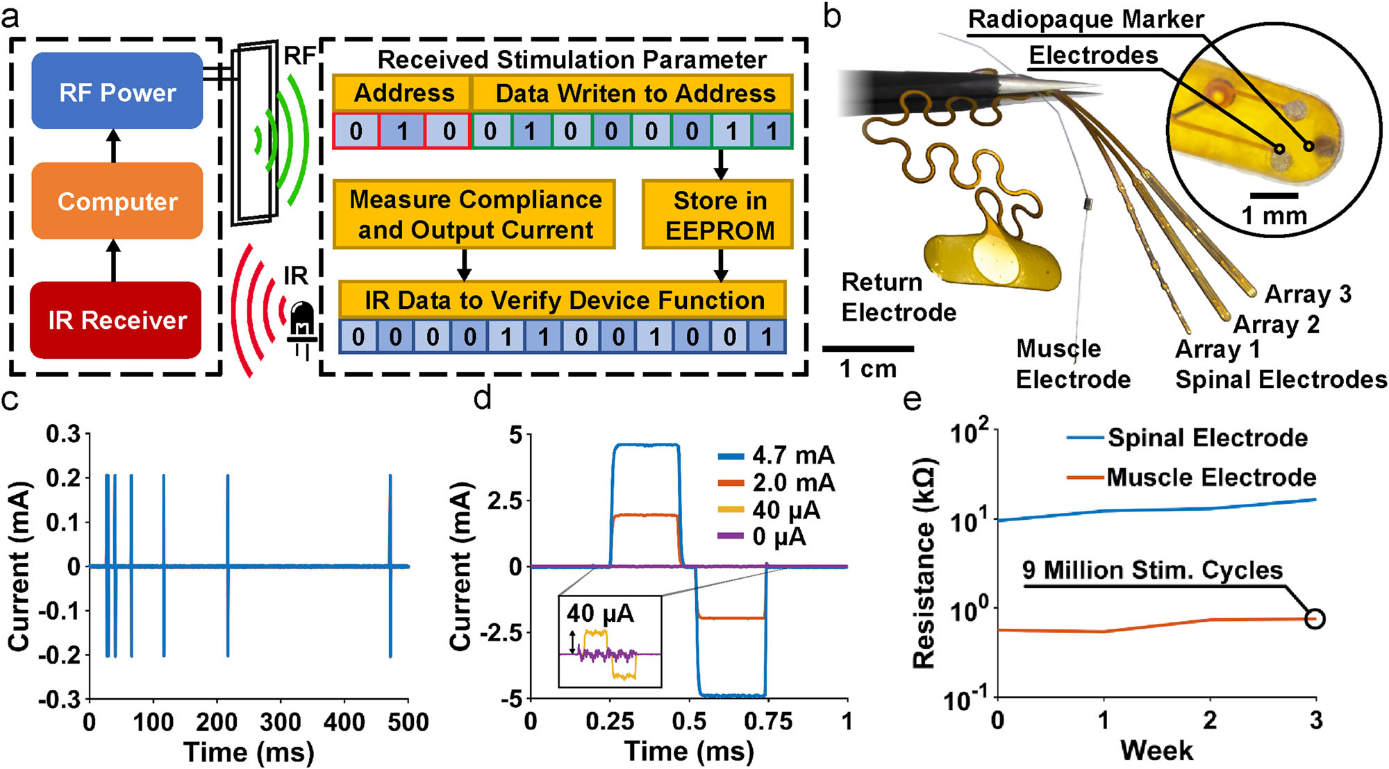
Combined RF ASK and IR modulation16–18, as developed in previous low power wireless systems, provides reliable two-way communication with the implants in a small footprint and with low power consumption as shown in Fig. 3a. The device is programmed via RF ASK by trans- mitting 3 bits for selection of a stimulation parameter (channel, amplitude, pulse width or period) followed by 8 bits to select the desired value. Information on stimulation parameters, voltage com-
Ir
communication. This digital communication enables a multifunctional platform which can be reconfigured with different electrode characteristics according to application requirements. Figure 3b shows a range of electrode variations in monopolar configuration, all using a large sur- face area return electrode to reduce return path stimulation effects.
The device is capable of controlling up to eight channels which can be distributed to a variety of peripheral and central nervous system Fig. 2 | Characterization of the antenna design and electrical device properties.
a Rendering of treadmill cage design with a dual loop transmitter antenna and infrared receivers. b Rendering of co-planar resonant antenna design showing the transmitter and receiver antenna coupling in Finite Element simulations of elec- tromagnetic field flux. c Corresponding power vs. load curve in the center of 56 cm × 16 cm arena with RF input power of 2 W for the 3-coil WPT and 2-coil WPT.
d Power harvesting capability vs. angular misalignments for both 2 W and 5 W of RF power. e Finite element simulations and measurements (displayed in numeric datapoint representing the hottest location measured) at steady state in saline solution when powered with 6 W of RF power.
5
substrates. In this work, the device delivers stimulation to both central (spinal epidural) and peripheral (intramuscular) electrodes. For spinal stimulation, micro-electrodes with 200 µm diameter are placed epi- durally on the spinal cord with a contact impedance of ~10 kΩ at 1 kHz as shown in Supplementary Fig. 11a, b. For muscle stimulation, braided stainless-steel wires coated with polytetrafluoroethylene with a crimped stainless-steel tube64,65 to increase contact surface area and reduce impedance ( ~ 500 Ω at 1 kHz Supplementary Fig. 11c, d) are used. Note that the core technology and fabrication processes of this device are based on modular designs that enable a high degree of flexibility of neural interfaces including commercially available solu- tions or custom electrodes. For example, electrode leads could, in principle, be used to stimulate intracortical electrodes or cuff elec- trodes on peripheral nerves. The scalable design of the monolithic device body enables free positioning of stimulation sites within the device footprint as shown in Supplementary Fig. 12a–c to target sites distributed across the rostrocaudal and mediolateral extent of the spinal cord. The onboard microcontroller enables complex stimula- tion protocols that might be used to improve functional outcomes; e.g., variable stimulus intervals used to reduce muscle fatigue66 as illustrated in Fig. 3c.
An 8-bit DAC sets the resolution of the current source which is capable of delivering up to ±24 mA. Setting the stimulation current range to ±4.7 mA allows for the balance of fine current control (40 µA) (Fig. 3d) with a dynamic range that is capable of both muscle and spinal stimulation. It should be noted that while high currents can be delivered to all channels, this may result in injury or animal discomfort in spinal cord applications; the primary intended use for high current stimulation is for muscle stimulation. For higher resolution, a lower dynamic range can be chosen by changing feedback resistors on the device; e.g., with a dynamic range of ±1.8 mA the resolution is 7 µA (Supplementary Fig. 14a). Currents are directed dynamically to each of the eight channels with the multi- plexer (40 µs switching latency), and stimulation parameters are controlled independently for each channel. Supplementary Fig. 13 and Supplementary Fig. 14b show an example in which each sti- mulation channel for both the muscle and spinal electrodes is wired to resistive loads (1 kΩ and 16.5 kΩ) that are similar to typical electrode impedance magnitudes, then tested in vitro with stimu- lation pulse durations between 100-1000 µs which are similar to typical durations used in FES applications67–69. In this example, the maximum current error is only ±12 µA (7 µA is due to the voltage error of the DAC and 5 µA due to the current driver) for a set current of 1 mA. This matches experimental data showing a maximum cur- rent error of ± 12 µA (Supplementary Fig. 15). This demonstrates the robustness of the analog front end. To deliver the programmed stimulation currents, especially in the case of high current applied through high impedance electrodes (Supplementary Fig. 14e), the device must be capable of operating with high voltage compliance.
The device features a maximum voltage compliance of ±20 V as shown in Supplementary Fig. 14c, d, and validated with a 10 kΩ load in the treadmill cage enclosure with an RF power of 5 W, observing variations of ±4 V across the enclosure volume (Supplementary Fig. 14d).
An important aspect of chronic stimulation in clinical applications is the need for biphasic stimulation capabilities with the option to deliver anodic or cathodic leading pulses70. Biphasic pulses allow for charge balancing, designed to reduce charge accumulation and irre- versible electrochemical processes at the electrode surface which can result in tissue damage or electrode degradation71,72. Charge balancing can also be achieved using a unidirectional current and a series capacitor73. However, this method requires a low output resistance and a correctly matched capacitor that depends on the electrode design.
This is why in the devices described here, biphasic stimulation was used for active charge balancing which enables versatile use with custom electrodes. This process is evaluated ex vivo by recording direct current through the stimulation electrode during chronic sti- mulation in saline solution and integrating current over time. The residual charge during 1.8 mA biphasic stimulation pulses at a fre- quency of 87 Hz is a maximum of 4.6 nC after 57 stimulation cycles Fig. 3 | Wireless communication, electrode design and characterization. a Block diagram of communication scheme. b Photograph of return, spinal and muscle electrodes. c Temporal control of stimulation patterns. d Amplitude control of biphasic stimulation. e Change in the impedance of the electrode, measured at 1 kHz, after continuous stimulation of over 9 million cycles.
6
(Supplementary Fig. 16a, b) which is within the limit of allowable residual charge before irreversible damage to either the tissue or electrode74.
The device can be used with a variety of electrode materials, impedances, and designs; in our experiments, we use both spinal epidural and intramuscular electrodes. Although electrode perfor- mance is distinct from the functionality of the device, we evaluate the chronic performance of the electrodes used in our current design by performing accelerated rate testing. We test spinal electrodes both within the water window of the electrode material (gold (<±1.2 V)) and above the water window at 1 kHz for 14 days at room temperature (Supplementary Fig. 17a, c, e). This reflects more than 1 billion stimu- lation pulses; given a typical FES stimulation rate of 50 Hz. Not accounting for in vivo physiological factors, this results in several months of real experimental time. Muscle electrodes, show no change in impedance and no obvious change in electrode appearance for stimulation applied within or above the water window (Supplementary Fig. 17b, d, f). This observation is expected given the large surface area and consequent low current density and material bulk. The smaller spinal electrodes, on the other hand, increase impedance by less than 15kΩ when operated within the water window, enabling chronic operation in small animal models. When spinal electrodes are driven outside of the water window, electrode impedances increase much more substantially (above ±1.4 V) and dissolution of the gold electrode coating results in electrode failure after 7 days corresponding to 5 months of real experimental time. These results are generally expected for the electrode sizes and materials used here and are independent of the overall performance of the device. Devices described implanted in this study generally remain functional for 4-6 weeks. Importantly, because of our system’s modular design, the sta- bility of the device is independent of the electrode materials or designs utilized (e.g., platinum vs. gold). Thus, electrodes that have better chronic performance can be easily implemented without requiring changes to the fabrication techniques or compromising electronic device performance16.
Stimulation using constant current mode (1 h sessions repeated 5 days a week for 16 weeks) using an accelerated lifetime test (9 million pulses at 1 mA at 1000 Hz at room temperature matching parameters used for spinal cord stimulation75) results in similar degradation (Fig. 3e) and compares to results from literature (Supplementary Fig. 18a–c)76.
Device Mechanics And Materials
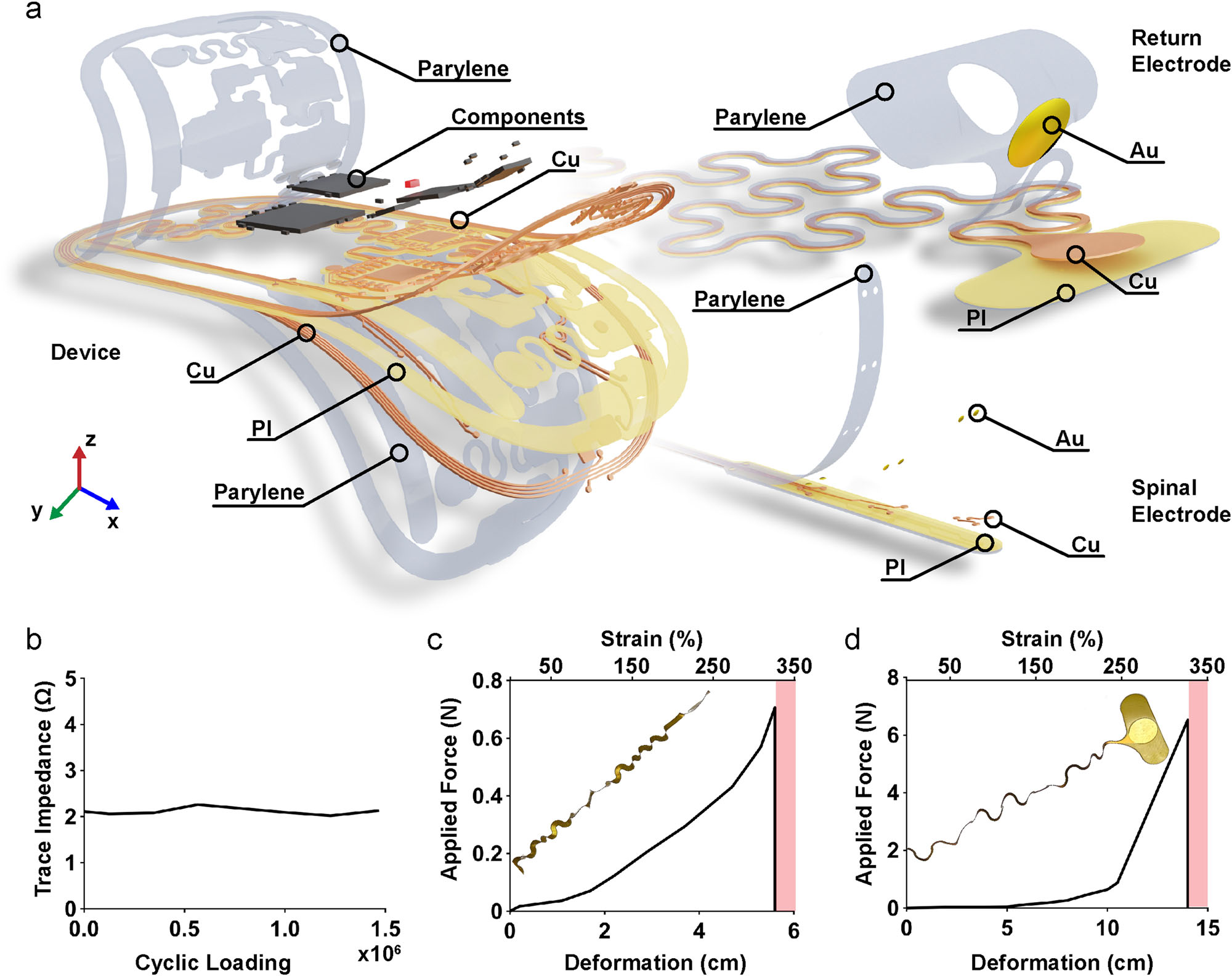
The materials used to fabricate the device and the design of its overall mechanics were chosen to maximize the stable long-term operation and reduce the impact on surrounding tissues. The device consists of a thin, dual-layer flexible circuit board with a polyimide (PI) backing, combined with gold (Au) plated copper (Cu) traces populated with off- the-shelf ICs as shown in Fig. 4a. Devices are conformally coated with Parylene-C allowing for both biocompatibility with surrounding tissues and protection from corrosive biofluids. The encapsulation is ther- mally stressed in an accelerated rate test at 37 °C, 60 °C, and 90 °C showing an acceleration factor of 0.32 using Arrhenius scaling with an estimated device lifetime of 3 months at physiological temperatures (37 °C) (Supplementary Fig. 19a–d). This thin layer stack (100 µm) results in flexible device mechanics that enable the device to conform to the curvature of the body at the implantation site, minimizing impact on animal mobility or adverse interactions with surrounding soft tissue. To further improve mechanical biocompatibility, rigid islands consisting of ICs and a high density of circuit traces primarily made of hard materials such as silicon and copper (70 GPa −180 GPa) are fully encapsulated with silicone (360 kPa −870 kPa) to match the elastic modulus between the surface of the device and soft body tis- sues (0.1 kPa −10 kPa and 1 kPa −5 MPa respectively)15,77–82. Highly stretchable interconnects link the device body to the electrodes, decoupling the movement of the implanted electrodes from the main device body. By incorporating strain-isolating mechanical designs using self-similar serpentine interconnects83 that minimize tensile strain within the copper traces, device deformations are kept well below the plastic regime, thereby enabling indefinite strain cycles without damage.
Performance of these interconnects is evaluated using finite ele- ment simulation to ensure elastic deformation of all conductive ele- ments within the stretchable interconnects under physiologically relevant levels of strain estimated from a µCT image of the spinal and return electrode displacement (Supplementary Fig. 20). Supplemen- tary Fig. 21a (left) shows a simulated strain profile of the copper traces (visibility of the plastic layers is turned off for clarity) from the side and top view indicating a maximum strain of 0.77 % when displaced (x = 3 mm, z = 5 mm) which approximates the deformation the inter- connect experiences when the spinal electrode is inserted between the lumbar vertebrae (see Supplementary Fig. 20). The simulation results are further validated with a benchtop experiment closely matching deformation patterns of the computational results (Fig. 4c). We also examine the strain caused by the placement of the return electrode, which is positioned laterally by elongating the interconnectby as much as 50% (Supplementary Fig. 21b). This is accomplished with self-similar serpentines that improve strain-isolating mechanics to minimize cop- per stresses43. Supplementary Fig. 21b (left) shows the simulated strain profile of the copper traces in top and side views. Maximum strain of 2% is observed when the interconnect is displaced (y = 20 mm). Com- putational results match bench top tests closely as shown in Fig. 4d (right). Engineered elastic-regime deformation of the copper traces within the interconnects14 enables repeated strain cycles ( > 1.5 million, Supplementary Fig. 22) without loss of electrical conductivity in the trace, as demonstrated in cyclic strain experiments with monitoring of trace impedance (Fig. 4b). Safety margin for these interconnects is determined by the maximum strain before failure. For the spinal electrode interconnect, the maximum strain is 311% which corre- sponds to a displacement of 56 mm (Fig. 4c). For the return electrode, the maximum strain is 330% which corresponds to a displacement of 140 mm (Fig. 4d). In both cases, displacements and strains are well beyond those that might occur during device implantation of which none of the 21 implantations show signs of electrode damage imme- diately after surgery (Supplementary Table 2). Without the use of strain-isolating serpentine interconnects the maximum strain sig- nificantly decreases to a maximum strain of 10.7% which corresponds to a displacement of 3.1 mm (Supplementary Fig. 23), demonstrating the robust mechanical properties of this device.
Compatibility Of Implanted Devices
The procedures for implanting the device are similar to those descri- bed in previous work on spinal epidural stimulation in the rat29. The electrode is inserted into the epidural space through a partial lami- nectomy between L3 and L4 and positioned at the L1 and L2 vertebral levels to span the rostro-caudal extent of the lumbar spinal cord. It is then cemented to a vertebral screw placed in the L4 vertebra (Sup- plementary Fig. 24). The antenna and electronics are placed sub- cutaneously between back muscles and skin, centered over the spinal column and between the pelvis and ribs (Fig. 5a). Muscle electrodes are tunneled subcutaneously to the hindlimb and inserted intramuscularly in individual muscles (biceps femoris posterior in these examples) (Supplementary Fig. 24). The overall procedure takes ~2-3 hours. Post- operative X-rays are used to monitor the placement and integrity of the implanted device (Fig. 5a). Tungsten markers within the spinal electrode are used to evaluate electrode placement and to estimate contact locations in the spinal column (Fig. 5a). Figure 5b illustrates the mechanical flexibility of the implanted device, with the device readily conforming to both extended and highly curved body positions. The
7
components are visualized in vivo with µCT imaging, illustrating the location of the components when fully implanted (dorsal view in Fig. 5c and cross-sectional view in Supplementary Fig. 25).
The subdermal implantation of the device enables animals to recover quickly after surgery (Supplementary Fig. 26) so that chroni- cally implanted animals are visually indistinguishable from naïve ani- mals (Fig. 5d). Spontaneous exploratory activity levels decrease in the first week after implantation but return to normal levels by the second week (Fig. 5e). Hindlimb kinematics, evaluated as ranges of joint motion, during treadmill locomotion are similar in animals measured before and after implantation (Fig. 5f). In-cage trajectory tracking for 30 minutes indicates less exploration in the first week after surgery compared to before surgery (see Supplementary Fig. 27), but exploration returns to control levels in week 2. These observations highlight the advantages of this fully implanted system, showing that after an initial recovery period of ~1 week, the implanted device has minimal impact on animal behavior and locomotion.
Stimulation Control And Animal Kinematics
Evaluation of the performance of chronically implanted devices in anesthetized animals is conducted using a circular transmitter antenna (Fig. 6a) positioned above the rat for power supply and communica- tion (RF power 3-5 W). Movements evoked by spinal and muscle sti- mulation are monitored by kinematic tracking of the limb with DeepLabCut (DLC), with the magnitude of the evoked movement quantified as the maximal displacement of a point on the toe (Fig. 6b, c). Figure 6d illustrates an example of the effects of gradually increasing current amplitude applied to contact on the spinal elec- trode (channel 1, 4 Hz, 500 ms duration), showing that the device can be used to produce graded activation of neural substrates with responses saturating at high levels of stimulation. A similar example is illustrated in Fig. 6e for graded responses evoked from intramuscular stimulation (c5, 4 Hz, 500 ms duration). As summarized in Fig. 6f, the amplitude of the evoked response from both spinal and muscle sites varies systematically with applied current, resulting in standard recruitment curves that can be used to control hindlimb movements.
Importantly, in this experiment the device is able to control current ranges appropriate for both spinal (10 µA to 1 mA, typically ~200 µA) and muscle (1 mA to 5 mA, typically ~2 mA) sites, providing graded and well-controlled recruitment of each. Similar recruitment curves are obtained for each individual spinal and muscle contact site on the implanted device (Supplementary Fig. 28). The performance of the device is monitored through IR communication throughout all sti- mulation trials, and in all cases illustrated here the harvested power provides sufficient margins; i.e. the harvested voltage was always greater than the voltage required to source the required currents (Supplementary Fig. 29). Note that the current ranges used here do not fully saturate this muscle, likely reflecting the large size of biceps Fig. 4 | Material overview and mechanical characterization of the device.
a Exploded view rendering of each material layer used in the device, the return electrode, and the spinal electrode. b Change in trace impedance of the serpentine interconnect during cyclic loading measured at 1 kHz. c Strain stress curve of the serpentine structure for the spinal electrode, and d the return electrode.
Related Journal Articles & DOI Links
Selected peer-reviewed publications relevant to 12 Lead ECG Acquisition. Click the DOI to access the full paper (may require institutional access).
-
1. Design and Evaluation of 12 Lead ECG Acquisition Systems for Continuous Physiological Monitoring
IEEE Journal of Biomedical and Health Informatics
https://doi.org/10.1109/JBHI.2020.2981234 -
2. Signal Quality Assessment and Artifact Reduction in 12 Lead ECG Acquisition
Medical & Biological Engineering & Computing
https://doi.org/10.1007/s11517-020-02145-6 -
3. Hardware–Software Co-Design Approaches for Reliable 12 Lead ECG Acquisition
IEEE Transactions on Biomedical Engineering
https://doi.org/10.1109/TBME.2019.2895762 -
4. Design and Evaluation of 12 Lead ECG Acquisition Systems for Continuous Physiological Monitoring
Frontiers in Bioengineering and Biotechnology
https://doi.org/10.3389/fbioe.2020.00123 -
5. Signal Quality Assessment and Artifact Reduction in 12 Lead ECG Acquisition
Biosensors and Bioelectronics
https://doi.org/10.1016/j.bios.2021.112345 -
6. Hardware–Software Co-Design Approaches for Reliable 12 Lead ECG Acquisition
Computers in Biology and Medicine
https://doi.org/10.1016/j.compbiomed.2021.104567 -
7. Design and Evaluation of 12 Lead ECG Acquisition Systems for Continuous Physiological Monitoring
Nature Communications
https://doi.org/10.1038/s41467-020-12345-6
Why Choose Us?
Bangalore guidance for robotics, Spectre and autonomous systems projects.
Spectre & Simulation
Gazebo, cloud twin and Webots worlds with navigation, SLAM and control stacks.
Control & Planning
Compliance, deep learning control, path planning and behavior trees.
Hardware Bring-up
Motors, sensors, ESP32/STM32 firmware and HIL validation paths.
Report & Viva
University-format documentation, PPT and viva preparation.
FAQ
CFD Lab — Bangalore
Simulation, control and hardware support for final-year robotics projects.
Stacks
Worlds
Digital Twin
Control
Robots
Offline
Bring-up