Check For Updates
Hansel Alex Hobbie1, James L. Doherty1, Brittany N. Smith1, Paolo Maccarini1,2 & Aaron D. Franklin
1,3
With the growth of additive manufacturing (AM), there has been increasing demand for fabricating conformal electronics that directly integrate with larger components to enable unique functionality. However, fabrication of conformal electronics is challenging because devices must merge with host substrates regardless of curvilinearity, topography, or substrate material. In this work, we employ aerosol jet (AJ) printing, an AM method for jet printing electronics using ink-based materials, and a custom-made lathe mechanism for mounting flexible substrates and 3D objects on a rotating axis.

Using this method of lathe-based AJ printing, conformal electronics are printed around the circumference of rotational bodies with 3D curvilinear surfaces through cylindrical-coordinate motion. We characterize the diverse capabilities of lathe AJ (LAJ) printing and demonstrate flexible conformal electronics including multilayer carbon nanotube transistors. Lastly, a graphene sensor is conformally printed on an inflated catheter balloon for temperature and inflation monitoring, thus highlighting the versatilities of LAJ printing.
Additive manufacturing (AM) of electronics is a promising approach for pursuing new application spaces with cost-effective, readily customizable devices that would not be well-suited to conventional fabrication1–3. Con- ventional fabrication methods require rigid planar substrates and restrictive processingsteps(e.g.,hightemperatures,vacuumconditions),whichhinder application formats beyond that of chips and boards4,5. Alternatively, AM methods can move beyond planar structures and restrictive processing techniques to achieve three-dimensional (3D) fabrication of electronic
Flexible/Stretchable
electronics8–10, organic electronics11–13, and conformal electronics14,15, which refers to devices that are built to situate flush with their host substrate (regardless of rigid 3D topography or dynamic movement).
Conformal electronics address a distinct need for electronic func- tionality being integrated onto diverse flexible surfaces, yielding notable advancements in on-skin/wearable technologies16–19, embedded compo- nentry for aerospace20, and Internet of Things devices21–23. While the applications of conformal electronics are numerous, the manufacturing techniques for building such devices are limited. Methods for realizing conformal electronics fall into two major categories: (1) soft lithography followed by transfer/stamping24–27 and (2) direct-write (DW) printing28–31.
Soft-lithography techniques use conventional fabrication to produce elec- tronicdevicesonflexiblesubstrates;thesetechniquesarewellestablishedbut alsocomplex,expensive,andrestrictive,asmentionedearlier.Then,byasoft transfer or stamping process, the fabricated devices are wrapped con- formallyonto a target component.Although effective forsome applications, this transfer approach lacks the versatility of AM and faces obstacles in scaling up production. On the other hand, DW printing methods are inherently 3D and embody the principles of AM technology in providing a simple, cost-effective,and adaptable fabricationprocessthat istrulyadditive in nature28.
A distinct advantage of DW printing approaches for conformal electronics is their non-contact deposition of conformal microstructures using a broad catalog of printable materials28. Within DW printing methods, droplet-based approaches such as aerosol jet (AJ) printing32–34 and inkjet printing35–37 have substantial value for their ability to deposit virtually any material that can be suspended in a colloidal ink solution.
Inkjet
printing38,39, AJ printing offers improvements of specific benefit to con- formal electronics fabrication based on its large standoff distance (3–5 mm above the target substrate) and versatile methods for aerosolized deposition40–42 (see Supplementary Fig. 1). Due to the jetting nature of AJ printing, changes in distance or angle between the print nozzle and target substrate have reduced effect on the thickness and width of printed traces until reaching overly oblique deposition (>135°) and large standoff dis- tances (>5 mm)43. These unique qualities enable conformal AJ printing onto complex structures with a range of surface conditions (e.g., material
1234567890():,;
1234567890():,;
roughness or topography) because the jetted material can be deposited onto surfaces from a distance44–47. Although AJ printing is ideal for achieving conformal printing, there are limitations when a substrate possesses curvilinear features that are steep enough to make the angle of deposition from the print nozzle far off orthogonal, thus severely impacting print quality. To achieve conformal printing for curvilinear substrates a more sophisticated motion system is required that can adequately move and position the substrate at an ortho- gonal angle of print incidence. There exist advanced motion systems like 5-axis trunnion-based printers that utilize two rotational axes in addition to 3D linear motion to fix the orientation of the substrate and nozzle at an orthogonal print incidence regardless of substrate curvilinearity48,49. The drawback of these systems is the machine complexity needed to achieve complete 5-axis control, which can prohibitively raise cost when scaling up to commercial-level manufacturing. A less complex alternative for con- formal printing onto curvilinear surfaces is to use a motion system with one axis of rotation. With rotation around just one axis, it is possible to move a nozzle circumferentially around radial curvature, which is ideal for con- formity around curved 3D shapes like cylinders. One-axis rotation does not fully solve the problem of conformity onto multidirectional curvature (e.g., spherical surfaces); however, there are a number of conformal applications that can be unlocked just by utilizing a motion system with cylindrical- coordinate capabilities.
There are specific application needs for conformal electronics on 3D rotational bodies that would benefit from a simple yet versatile AM technique. For example, catheters and inflatable catheter balloons, which are inherently cylindrical and rotatable around a single axis, are used in surgical procedures throughout the body such as endoscopy 50, angioplasty 51, and elution-based drug delivery 52. The cylindrical 3D body and soft-material surface of these catheters make it difficult to directly add conformal electronics, with a few demonstrations of con- formally adding functionality for tactile detection53, temperature sensing54, and ablative procedures55,56. The methods used to realize these limited demonstrations were all related to soft lithography with a transfer process that placed electronics onto the catheters57–60. However, these techniques require a secondary substrate to be used with the catheter, can only provide semicircular conformity, and require multi- step conventional processing. Alternatively, AJ printing shows great potential for conformal DW fabrication of electronics on catheters. In works by Jordan et al. and Will et al., AJ printing was used to fabricate resonant circuits on the surface of catheters to provide low-profile tracking of the catheter during MRI procedures61,62. Although the authors demonstrated functional conformal devices on catheters, they both used strictly cartesian movement systems that limited their fabri- cation to a process requiring multiple printing steps and manual inter- action to correctly fix the substrate under the nozzle. By utilizing a cylindrical-coordinate motion system with rotational control, the lim- itations of cartesian AJ printing could be overcome and conformal DW printing onto catheters would become trivial such that full designs could be patterned in a single print step.
In this work, we developed a custom solution to achieve conformal AJ printing onto flexible curvilinear surfaces and 3D rotational substrates that utilizes lathe-based cylindrical-coordinate motion to rotate a substrate fixed on an axis. Evidence of the effect of print incidence on conformal printing applications is presented, along with a thorough exploration of the lathe AJ printing (LAJ) technology—coined for its similarity to the function of an axially rotating lathe. This printing technique allows for cartesian motion to be translated into 3D cylindrical rotation, which is ideal for conformity on 3D curvature. The mechanisms of operation are presented along with a full characterization of mechanical performance down to the micron scale. The capabilities of the LAJ printing method are highlighted by demonstrating multiple applications of the technology with relevancy to flexible and sus- tainable electronics, complex-geometry conformal printing, as well as catheter-based electronic devices. In the final demonstration, we demon- strate DW printing of flexible electronics onto inflatable catheter ballons, which could simplify the integration of electronics in the many medical procedures involving catheters and catheter balloons. Notably, we demonstrate that our system is applicable for any catheter with substrate dimensions under 40 mm in diameter, emphasizing that LAJ printing can be employed for conformal on catheter electronics with many possible applications.
Results And Discussion
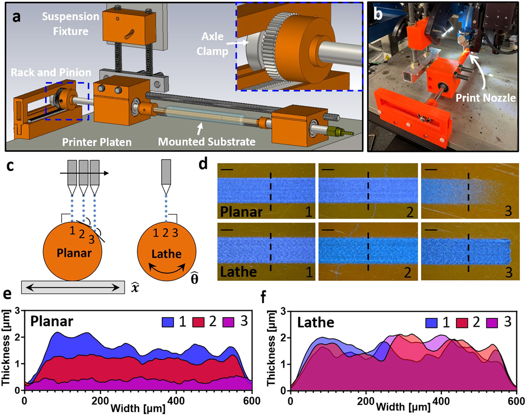
Lathe printer attachment conceptualization and design To achieve cylindrical-coordinate-based control of printing, a custom attachment for the x–y platen of a commercial AJ printer (Optomec AJ300) was developed, as shown in Fig. 1. In the computer aided design (CAD) diagram of the lathe mechanism, the various features that provide the lathe functionality can be readily identified. The primary feature worth noting is the mechanism for translating linear motion in the cartesian x-axis to rotational motion in the cylindrical θ-axis while maintaining linear motion in the axial direction along the y/z-axis. This translation is achieved by the rack, pinion, and axle clamp, which serve as the junction between the printer-controlled platen and the suspended rotating axle. The pinion is affixed on an axis above the rack by a linear motion shaft with screw-tapped ends that allow for on-axis attachments like the pinion and axle clamp. The pinion interlocked with the platen-fixed rack provides the rotation to the suspended axle, and the axle clamp, which locks onto a ball bearing in a guide rail, providing the linear motion to the shaft regardless of position on the x-axis (see Fig. 1a). This shaft is suspended above the rack by a position- adjustable support with two ball bearings to allow smooth rotation. This support is attached to the printer body separately from the platen and has adjustable guides to set the rotating axle directly under the nozzle tip.
Dependingonthe directionoftheplatenmovement,thesuspendedaxle can freely rotate within the bearings, slide through the bearings to allow linear axial motion, or both simultaneously. The length of the shaft determines the range of axial motion, and full circumferential rotation enables deposition onto substrates of any diameter <40 mm, which is the largest substrate- holding mandrel that can be fit under the nozzle (seeSupplementary Fig. 2).
The significant advantage of utilizing a platen-mounted rack to translate linear motion to axial rotation is that this is a readily scalable solution, such that multiple suspended axles can be supported by the system without the addition of any motors or components beyond the additional substrate- supporting mandrels.
Usingthismechanism,cylindrical-coordinateLAJprintingisachieved, making it possible to conformally print around the entire circumference of rotationally symmetric bodies without manual interaction. Examples of substratesthatthisconfigurationcanconformallyprintontoincludeflexible films wrapped around cylinders, 3D rotational solids (cylinders, cones, helices, etc.), and hollow rotational solids such as tubing or balloons.
Cylindrical bodies are the ideal case for this system, as the print incidence will be perfectly normal for the entire curved surface. However, with the mechanism it is possible to conformally print around 360° of rotation for any solid with a definable axis, which supports a high degree of applicability to any number of substrate geometries.
Significance of the angle of print incidence in conformal printing The angle of print incidence for AJ printing is defined here as the angle between the target substrate and the aerosol stream that is responsible for material deposition onto the substrate. In the ideal printing scenario, the angle of incidence is always kept at 90° such that the deposition is normal to the substrate and factors affecting thin-film formation (e.g., surface hydrophobicity, inclination) are limited63–65. Maintaining normal incidence during deposition is important because at increasing degrees of hydro- phobicity, a droplet has less surface adhesion and will roll across a surface more easily at oblique angles of incidence. Through the practice of treating surfaces to lower hydrophobicity and keeping the print nozzle orthogonal over the substrate, print adhesion improves greatly for a variety of sub- strates. In planar AJ printing onto a flat substrate, it is trivial to maintain normal incidence; however, for conformal printing applications where the
2
substrate topography presents varying degrees of nonplanarity, the ideal normal incidence is almost entirely lost with planar AJ printing. While the loss of normal incidence does not strictly mean an inability to print con- formally,itdoesestablishadiscrepancyfromtheassumedidealcasethatwill create issues in print uniformity and design at increasingly steep angles of incidence. An example of this issue is presented in Fig. 1c–f, wherein planar and LAJ conformal printing of graphene ink onto a polyimide sheet wrapped about a cylindrical body is compared. The illustration in Fig. 1c showsthatforplanarAJ printing,the angleof printincidenceisonlynormal at the acme of the cylinder (position 1) and continues to increase as the cylinder slopes away from the x-axis (positions 2 and 3). In contrast, LAJ printing maintains normal print incidence around the entire circumference ofthecylinderbecauseoftheθ-axisrotationofthesubstrate,whichholdsthe three positions as the acme of the cylinder directly under the nozzle throughout printing. It should be noted that in this experiment, the standoff distancefortheplanarcaseisalsoincreasingwithangleofincidencebecause the nozzle is not actively moving in the z-axis to correct for the change in distance above the substrate. However, even with active z-axis control the angle of incidence will be non-orthogonal and achieving adequate con- formity around a circumference remains a major challenge.
ThesignificanceofthedifferencebetweenplanarandLAJprintingona curved surface becomes visually clear in Fig. 1d when looking at the quality ofprintedtracesbetweenthetwoprintmethodsatpositions1,2,and3(each ~5.9 mm apart). At positions 1 and 2, the planar and lathe approaches produce visually consistent traces because of the near-normal incidence in the planar case. At position 3, however, when the angle of incidence is steepest (>160°) for the planarapproach, the printed trace becomes thin and patchy in comparison to the lathe printed trace, which maintains a uniform appearance consistent with positions 1 and 2. Cross-sectional thickness profiles of these printed traces at the corresponding positions are shown in Fig. 1e, f for the planar and lathe approaches, respectively. The planar traces exhibit nonuniformity in thickness betweenthe threepositions, whereas the conformal traces produced by LAJ printing are effectively the same thick- ness regardless of position thanks to rotation of the substrate keeping the incident anglefixed.From thisdemonstration, it is shownthat forsuccessful conformal printing onto 3D curved substrates it is critical to use a system with rotational movement because a planar cartesian motion system cannot provide normal print incidence for curved features of any kind.
Translation of motion and the importance of the diametric ratio Theratiobetweenthesubstratediameter(DS) and thepiniondiameter(DP), referred to as the diametric ratio (DS/DP) is of critical design importance because it can amplify or diminish the actual motion and print speed for the substrate under the nozzle. If the two diameters are equal, the x- and y- direction movement of the printer platen is translated at a 1:1 ratio with the θ- and z-direction movement of the rotating substrate. However, if the diameters are unequal then the translation of the x-direction platen movement to the θ-direction mandrel rotation will be multiplied by the diametric ratio, as illustrated in Supplementary Fig. 3. As a result, the true displacement (d) and printspeed (v) of the rotatingsubstrateinthe θ-and z- Fig. 1 | Lathe aerosol jet (LAJ) printing mechanism and the impact of angle of print incidence on conformal films. a CAD diagram of LAJ printer attachment and closeup image of the rack and pinion with axle clamp. b Picture of LAJ printer attachment secured to the printing system with deposition nozzle located above cylindrical rotating mandrel. c Illustration of the angle of print incidence for planar (stage linear motion in x) and lathe (substrate rotational motion in θ) AJ printing.
d Images of planar and LAJ printed graphene traces at positions 1, 2, and 3 separated by ~5.9 mm for each method (dashed line indicates cross-section location with scale bar of 250 µm). e Thickness profiles across the width of planar AJ printed graphene traces at positions 1, 2, and 3—note the significant drop in thickness at position 3 where the incident angle was ~75°. f Thickness profiles across the width of LAJ printed graphene traces at positions 1, 2, and 3 showing consistency of thickness distribution at each site.
3
directions will differ from the movement and print speed of the planar platen according to the four equations provided in the Supplementary Information.
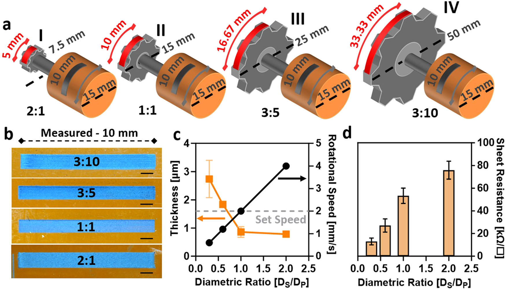
Although it is ideal to match the diameters of the pinion and a given substrate, it is much easier to acknowledge the difference in the two dia- meters, as mapped out in Supplementary Fig. 4. For the work presented here, four pinions were tested with diameters of 7.5, 15, 25, and 50 mm, and a 15 mm cylindrical mandrel (Supplementary Fig. 5) to vary the diametric ratio as illustrated in Fig. 2a. Due to the effect of the diametric ratio, it is important to adjust the design file by either elongating or shortening dimensions in the θ-direction to achieve the desired pattern. In Fig. 2b, the as-printedtracesforeachofthediametricratioswereimaged,andeachtrace is shown to be 10 mm in length as intended, despite the diametric ratio affecting the design dimensions. Since the diametric ratio will also have an effect on the rotational speed, it is important to consider how the true rotational speed of the substrate will impact printing. For the graphene traces, a linear print speed of 2 mm/s was set for the motorized platen, and the actual print speed of the rotating mandrel was determined according to the diametric ratio, as plotted in Fig. 2c for the four example cases. In this plot, the thickness of the printed traces is also provided relative to the true printspeed.Aswould beexpected,forfasterprintspeedsathigherdiametric ratios the printed tracesbecome thinner than whentheyare printed atlower diametric ratios with slower print speeds. Consequently, for the thicker tracesprintedwiththelowestdiametricratiosthereissubstantiallylesssheet resistance than for the relatively thinner traces produced at higher ratio values, as shown in Fig. 2d. This trend in sheet resistance is also expected, as the thicker traces contain a higher density of conductive material and thus exhibit lower sheet resistance than the thinner traces with less material.
These results (Fig. 2) highlight the importance of understanding and characterizing the effect of the diametric ratio on LAJ printing so that appropriate design choices can be made.
Characterizing Performance Of Lathe Mechanism
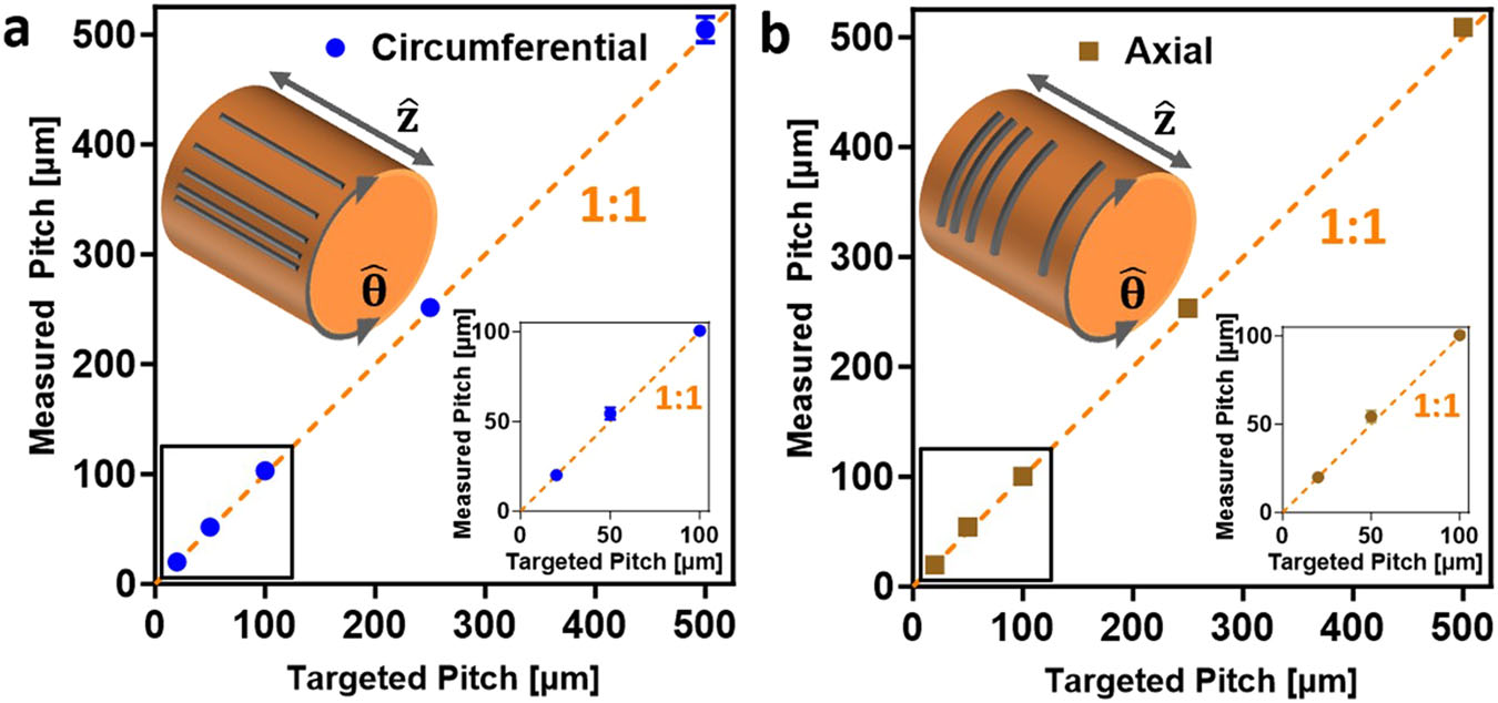
Considering the custom nature of this lathe mechanism prototype, it was critical to determine the accuracy of movement that is provided by the translation to cylindrical-coordinate motion. To measure the accuracy achieved by the lathe system, graphene traces were printed with center- to-center pitch from 500 µm down to 20 µm in both the circumferential ð^θÞ and axial ð^zÞ directions with a 1:1 diametric ratio (Supplementary Fig.
6). From the observed precision between the designed and measured pitch between lines, as shown in Fig. 3, the lathe mechanism was demonstrated to have controllable and accurate movement down to 20 µm in the circumferential and axial directions. Both the achieved resolution and uniformity of the lathe printing process on a cylindrical substrate are equal to the capabilities of planar printing onto flat surfaces because parity is provided by the rack and pinion motion translation mechanism. Additionally, to show the circumferential and axial direc- tions can also be accurately moved simultaneously, traces were printed with center-to-center pitches of 500 µm down to 50 µm in ±45° angles relative to the axial direction with a 1:1 ratio (see Supplementary Fig. 7).
Lastly, to verify that the lathe system accuracy is highly repeatable and maintained throughout printing, an experiment was devised in which the word “Duke” was printed three times in rapid succession with a 1:1 ratio and overlaid in the same location each time for print speeds of 2, 4, 6, 8, and 10 mm/s. The resulting prints are shown in Supplementary Fig.
8 with videos of the lathe mechanism operating at print speeds 4–10 mm/s provided in Supplementary Movie 1. The distinct lack of shifting and the clearly legible “Duke” for each of the print speeds is indicative of the accuracy and repeatability of the lathe mechanism across multilayer and variable-speed printing.
Conformal and flexible electronic devices using LAJ printing To demonstrate conformal and flexible electronics fabricated with LAJ printing, electronic devices of resistive traces, capacitors, and thin-film transistors (TFTs) were printed onto flexible substrates wrapped around cylindrical mandrels with a 1:1 diametric ratio. First, it was discovered that the resistance of infilled traces of printed graphene is dependent on the arc length (defined by the central angle and radius of the arc) and the infill direction, with axial infill yielding higher resis- tance at longer arc lengths, as seen in Fig. 4a. Resistance was measured in a two-terminal fashion by positioning micromanipulator probes at the ends of the long side of a trace. The two infill directions were tested Fig. 2 | Characterization of lathe system translation of motion. a Illustration of the ratio-adjusted design of lathe aerosol jet (LAJ) printed graphene traces for the four diametric ratios studied. b Microscope images of LAJ printed graphene traces using different diametric ratios, scale bar is 1 mm. c Thickness of graphene traces and rotational print speed for different diametric ratios with error bars indicating standard deviation using n = 3 samples for each ratio. d Plot of sheet resistance for graphene traces printed using different diametric ratios with error bars indicating standard deviation using n = 3 samples for each ratio.
4
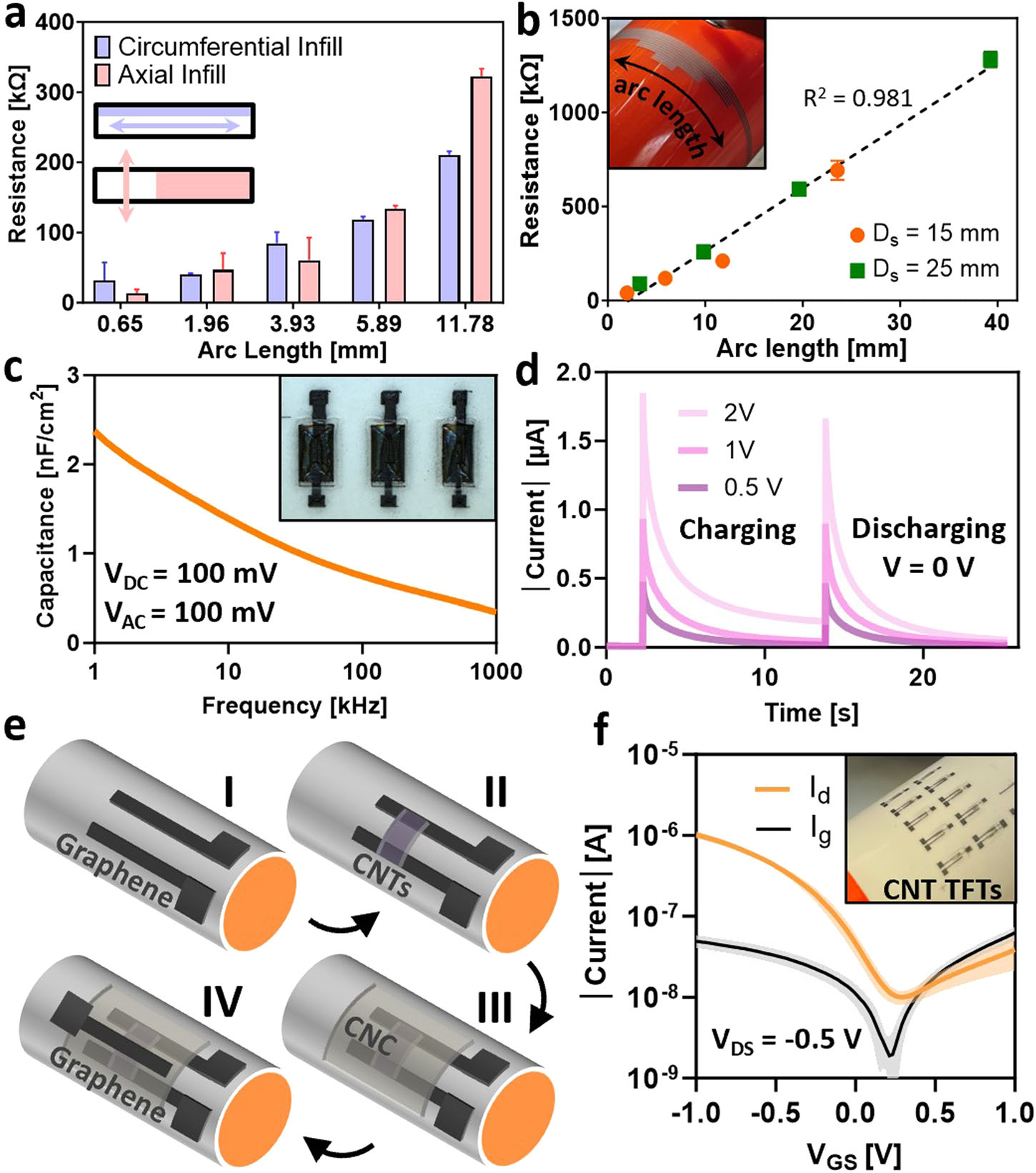
by printing graphene traces along the circumference of a substrate- wrapped 15 mm diameter mandrel with different central angles of 5°, 15°, 45°, and 90° defining the arc lengths. These traces exhibited mostly similar values of resistance up to an arc length of 11.78 mm (central angle of 90°), where the resistance of the arc trace began to deviate from previous values. This deviation is due to the axial-infilled trace being printed perpendicular to the arc length direction, which uses more individual microstrip lines to form a given trace. In contrast, the circumferential-infilled trace used longer printed lines with increasing arc length, but the number of lines used to form the trace remained the same. Thus, the circumferential-infilled traces maintained a linear resistance across increasing arc lengths while the axial-infilled traces showed a jump to higher resistance for long arc lengths because it was composed of more individual lines than the circumferential infill.
Therefore, the infill patterns for the materials throughout this work were chosen in accordance with having the fewest individual lines
Cnt-Tfts. A Resistance Comparison Between
multiple arc lengths of graphene traces using dif- ferent infill directions with error bars indicating standard deviation using n = 3 samples for each data
On A 25 Mm Mandrel. F Device Subthreshold Char-
acteristics of CNT-TFTs (inset is picture of devices
Respectively). Data For Both Curves Represent The
average (solid line) ± the standard deviation (shaded region) for seven devices.
Pitch To The Actual Measured Pitch For The
a circumferential and b axial directions with error
Samples For Each Data Point And The Dashed Line
representing a 1:1 relation between the targeted and
Measured Pitch (Insets Are Magnified Plots Of The
smallest pitches).
5
being printed for each geometry on a device layer to ensure consistent resistance. In Fig. 4b, resistive traces of varying arc length were printed along the circumferences of 15- and 25-mm diameter mandrels using a diametric ratio of 1:1 and circumferential infill. Regardless of substrate diameter between the two mandrels, the resistance of the traces showed an expected trend of increasing resistance with arc length. These graphene traces were then measured by the four-point probe method and a relatively consistent range of sheet resistance values was observed across increasing arc length betweenthetwomandrels(SupplementaryFig.9).Theseresultsindicatethe reliable performance of LAJ printing along increasing circumferential dimensions while also showing scalable application to substrates with dif- ferent diameters.
While successful single-layer LAJ printing of electronic materials was critical to establish, the ability to fabricate multilayer electronics is more difficult and relies on accurate patterning and positioning between layers to achieve correct functionality. Given that AJ printing has shown great potential for producing eco-friendly and sustainable devices such as all- carbonrecyclableelectronics66,cellulosenanocrystal(CNC),acarbonaceous ionic dielectric material, was chosen for use in the presented multilayer electronics as an insulating layer. To demonstrate a three-layered carbon- based device, a two-plate capacitor of graphene contacts and CNC was fabricatedon a paper substrate wrapped around a 15 mm diameter mandrel using LAJ printing at a 1:1 ratio (Fig. 4c, d). The normalized capacitance across frequency for the capacitors of 0.81 mm2 overlapping plate area decreases in a nonlinear fashion in accordance with the ionic nature of the CNC dielectric67,68. Furthermore, under applied voltages of 0.5, 1, and 2 V, exponential behavior of the capacitor charging and discharging currents is observed with measured leakage current for the 2 V case that diminishes for the lower voltages. These results demonstrate that simple multilayer elec- tronic devices are readily fabricable with LAJ printing.
By expanding to four layers and using a top-gate transistor design that includes printed carbon nanotubes (CNTs) as the semiconducting layer, TFTs were fully LAJ printed on paper in accordance with the process flow illustrated in Fig. 4e. Briefly, source and drain contacts of graphene along with fiducial marks were printed onto a paper substrate mounted on a 25 mm diameter cylindrical mandrel. Then, the CNT channel was printed to bridge the two contacts followed by the CNC gate dielectric and a gra- phene top gate, all of which utilize the fiducial marks for correct alignment between the four TFT layers. It is worth noting that the toluene-based CNT inkusedforthesedevicescouldposesomecompatibilityissuesforsubstrates that display susceptibility to the toluene content, in which case, an alter- nativewater-onlyCNTinkshouldbeusedtoavoidanynegativeinteractions between ink and substrate69. The switching characteristics of these TFTs are shown in Fig. 4f, wherein the drain current (ID) and gate current (Ig) were measured for applied gate voltages (VGS) from −1 to 1 V with a constant drain to source voltage (VDS) of −0.5 V. The measured CNT-TFT devices possess repeatable and consistent switchingbehavior with an on/off-current ratio of ~102 and a full sweep range of only 2 V due to the ionic nature of the CNC gatedielectric drastically lowering the threshold voltage requirements.
These devices have similarly low threshold voltage requirements (VT < 1 V) and comparable device current ratios (ION/IOFF: 102–103) to previous examples of all-carbon printed TFT devices on paper despite the presented devices having no added ions or treatment to the wrapping polymer in the CNT channel66. However, these devices also suffer from a relatively high level of gate leakage current (Ig > 1 nA) that is a notable problem of devices with ionic dielectrics. The successful printing of these three-terminal, multilayer devices further corroborate the versatility and accuracy of LAJ printing across multiple layers and for different materials and substrates.
LAJ printing is demonstrably capable of fabricating electronic devices onto nonplanar surfaces for conformal and flexible electronic applications alike. Conformal printing onto complex shapes with LAJ printing From the demonstrations already presented, it is clear that LAJ printing achieves ideal orthogonal print incidence for conforming onto cylindrical bodies and flexible substrates bent around a convex radius. Coincidentally, without any modification to the actual lathe mechanism, the LAJ printing system also allows the print nozzle to be positioned at the focal point of concave curvature, as shown in Fig. 5a for a 15 mm diameter hollow half cylinder. In Fig. 5b, c, example patterns of graphene were deposited onto the concave mandrel with and without a fixed substrate to show that this setup can also be used to print onto flexible substrates bent into a compressive state at a concave angle.
Despite offering a simple and efficient method for conformal printing onto cylindrical curvature, the lathe-based approach still has limitations when working with multidirectional curves like spherical surfaces and nonuniform 2D curvatures. For complex geometries like these, the current maneuvering capabilities of the lathe prototype cannot achieve the ideal normal print incidence of 90°, and it may be better to consider systems with advanced functionality like the 5-axis printer. However, because of the standoff distance and jet-stream deposition of AJ printing, getting approximate uniformity in a printed trace is still possible for moderate angles of non-normal incidence. This tolerance of moderately non-normal incidence in conformal applications is demonstrated for LAJ printing in Fig. 5d, e by printing silver nanowires (AgNWs) onto a 3D-printed conical mandrel with a taper angle of 15°, resulting in a non-normal print incidence of 105° across the cone. For different substrates (e.g., cylindrical, conical, flat), the effects of printing with non-normal (oblique) incidence are iden- ticalanddeterminedbytheangleofprintincidencefromthenozzleposition relativetothesubstrate43.Insituationswheretheangleofincidencebecomes increasingly oblique, like the example in Fig. 1 of printing onto a cylinder usingplanarmovement,itwasobservedthatthicknessanduniformityofthe printed films will quantifiably reduce. Oblique incidence will similarly impact cylindrical printing onto conical substrates, resulting in negligible effect for small taper angles but forming thinner and less defined printed traces for large tapers with extreme obliquity. As a further example of the adaptabilityof conformalAJprintingforsmallanglesofobliquity,a1000 µL pipette tip with a gradual taper of 7.5° was used as the substrate for a conformal graphene helix, which was printed spiraling down the length of the pipette tip from its narrow end as imaged in Fig. 5f, g. These examples serve to represent the tolerance of LAJ printing to gradual multidirectional curvature with its simple motion, however, there will still be limitations to theconformalcomplexitythatcanberealizedwithoutaddingfurtheraxesof control.
Catheter balloon functionalized with on-surface LAJ printed
Graphene Sensor
Successfully fabricating conformal electronics onto 3D curvilinear sub- strateslikecylindersisanon-trivialchallengethatLAJprintingiswell-suited to solve in a simple and readily scalable fashion. However, AM of conformal electronics becomes increasingly difficult for substrates like catheters and catheter balloons, which possess soft polymeric surfaces and non-rigid inflatable bodies that add complication to the print process. Although dif- ficult to achieve, conformal fabrication of electronics directly onto catheter substrates is an important step in advancing catheter device technology for use in critical medical applications ranging from cancerous tissue ablation56,58 to implanting long-term devices within the body70,71. During these crucial medical procedures catheters are integral, yet knowledge of conditions around the catheter such as temperature, contact/degree of inflation, and external pressure are practically unknown without built-in electronic functionality.
To enable the fabrication of conformal electronics onto catheters and catheterballoons, LAJ printing was modified to include a system for on-axis inflation that permits hollow and inflatable rotational bodies to be mounted on the lathe mechanism, as portrayed in Fig. 6a. Since the on-axis inflation required no other modification to the lathe mechanism beyond the inclu- sion of a rotating air inlet, the system capabilities for printing onto any substrate <40 mm in diameter hold true, even for inflated catheters. In Fig.
6b, examples of six commercially available catheter balloons are plotted according to the possible balloon diameters for the product and their
Related Journal Articles & DOI Links
Selected peer-reviewed publications relevant to 12 Lead ECG Acquisition. Click the DOI to access the full paper (may require institutional access).
-
1. Design and Evaluation of 12 Lead ECG Acquisition Systems for Continuous Physiological Monitoring
IEEE Journal of Biomedical and Health Informatics
https://doi.org/10.1109/JBHI.2020.2981234 -
2. Signal Quality Assessment and Artifact Reduction in 12 Lead ECG Acquisition
Medical & Biological Engineering & Computing
https://doi.org/10.1007/s11517-020-02145-6 -
3. Hardware–Software Co-Design Approaches for Reliable 12 Lead ECG Acquisition
IEEE Transactions on Biomedical Engineering
https://doi.org/10.1109/TBME.2019.2895762 -
4. Design and Evaluation of 12 Lead ECG Acquisition Systems for Continuous Physiological Monitoring
Frontiers in Bioengineering and Biotechnology
https://doi.org/10.3389/fbioe.2020.00123 -
5. Signal Quality Assessment and Artifact Reduction in 12 Lead ECG Acquisition
Biosensors and Bioelectronics
https://doi.org/10.1016/j.bios.2021.112345 -
6. Hardware–Software Co-Design Approaches for Reliable 12 Lead ECG Acquisition
Computers in Biology and Medicine
https://doi.org/10.1016/j.compbiomed.2021.104567 -
7. Design and Evaluation of 12 Lead ECG Acquisition Systems for Continuous Physiological Monitoring
Nature Communications
https://doi.org/10.1038/s41467-020-12345-6
Why Choose Us?
Bangalore guidance for robotics, Spectre and autonomous systems projects.
Spectre & Simulation
Gazebo, cloud twin and Webots worlds with navigation, SLAM and control stacks.
Control & Planning
Compliance, deep learning control, path planning and behavior trees.
Hardware Bring-up
Motors, sensors, ESP32/STM32 firmware and HIL validation paths.
Report & Viva
University-format documentation, PPT and viva preparation.
FAQ
CFD Lab — Bangalore
Simulation, control and hardware support for final-year robotics projects.
Stacks
Worlds
Digital Twin
Control
Robots
Offline
Bring-up