Breast Mr Images
Julia A. Schnabel*, Christine Tanner, Andy D. Castellano-Smith, Andreas Degenhard, Martin O. Leach, Abstract—This paper presents a novel method for validation of nonrigid medical image registration. This method is based on the simulation of physically plausible, biomechanical tissue deforma- tions using finite-element methods. Applying a range of displace- ments to finite-element models of different patient anatomies gen- erates model solutions which simulate gold standard deformations.
From these solutions, deformed images are generated with a range of deformations typical of those likely to occur in vivo. The regis- tration accuracy with respect to the finite-element simulations is quantified by co-registering the deformed images with the orig- inal images and comparing the recovered voxel displacements with the biomechanically simulated ones. The functionality of the val- idation method is demonstrated for a previously described non- rigid image registration technique based on free-form deforma- tions using B-splines and normalized mutual information as a voxel similarity measure, with an application to contrast-enhanced mag- netic resonance mammography image pairs. The exemplar non- rigid registration technique is shown to be of subvoxel accuracy on average for this particular application. The validation method pre- sented here is an important step toward more generic simulations of biomechanically plausible tissue deformations and quantifica- tion of tissue motion recovery using nonrigid image registration.
It will provide a basis for improving and comparing different non- rigid registration techniques for a diversity of medical applications, Manuscript received September 12, 2001; revised October 23, 2002.
The work on biomechanical tissue modeling using ANSYS was supported by the EPSRC. The work of J. A. Schnabel was supported by EasyVision Advanced Development, Medical Imaging Information Technology (MIMIT), Philips Medical Systems, Best, The Netherlands. The work of C. Tanner was supported by the EPSRC under Grant GR/M52779 and Grant MIAS-IRC. The work of A. D. Castellano-Smith was supported by the EPSRC under Grant GR/M47294. The work of A. Degenhard was supported by the EPSRC under Grant GR/M52762. The Associate Editor responsible for coordinating the review of this paper and recommending its publication was M. Giger. Asterisk indicates corresponding author.
*J. A. Schnabel is with the Computational Imaging Sciences Group, Division of Imaging Sciences, Guy’s, King’s and St. Thomas’ School of Medicine, King’s College London, London SE1 9RT, U.K. (e-mail: julia.schn- C. Tanner, A. D. Castellano-Smith, D. L. G. Hill, and D. J. Hawkes are with the Computational Imaging Sciences Group, Division of Imaging Sciences, Guy’s, King’s and St. Thomas’ School of Medicine, King’s College London, London SE1 9RT, U.K.
A. Degenhard was with the CRC Clinical MR Research Group, The Institute of Cancer Research and the Royal Marsden NHS Trust, Sutton, Surrey SM2 Bielefeld, Germany.
M. O. Leach is with the CRC Clinical MR Research Group, The Institute of Cancer Research and the Royal Marsden NHS Trust, Sutton, Surrey SM2 5PT,
U.K.
Sheffield, Sheffield S10 2JF, U.K.
Digital Object Identifier 10.1109/Tmi.2002.808367
such as intrasubject tissue deformation or motion correction in the brain, liver or heart. Index Terms—Biomechanics, breast MR imaging, finite element methods, image registration, validation.
I
MAGE registration describes the process of establishing spatial correspondence between features in an image pair, or a dynamic or temporal sequence of images, in order to relate them for diagnosis, inspection of homologous positions, or temporal monitoring. The images might be acquired using the same or different imaging modalities, and can also be aligned to a computer model, or to locations in physical space for image guidance. Feature alignment is described by a transforma- tion, which, for rigid-body registration, describes differences in global patient positioning. For nonrigid registration, the transformation explains additional deformations due to soft tissue properties, surgical intervention, temporal changes due to tumor growth or radiotherapy treatment, and morphological differences between individuals. Also, nonrigid registration can compensate for geometric image distortion caused by the acquisition technique. There is a consensus in the literature that registration is needed to compensate for patient positioning and deformation. Various registration algorithms have been proposed, surveys of which can be found in –. Prior to clinical use, registration techniques need to be validated.
However, validation of registration performance suffers from the lack of knowledge as to if, how much, and where patient movement has occurred between and even during scanning procedures, and whether such movement affects the clinical usefulness of the data. To maintain clinical usefulness, and inherently improve patient treatment and health care, it is, therefore, mandatory to ensure that registration is successful.
How the success of medical image registration can be assessed and failure can be detected is laid out in a recent survey by Fitzpatrick , and will be discussed with an emphasis on validation of nonrigid registration in the following.
As a first step, a registration method can be assessed in an independent evaluation in the absence of a ground truth. An ini- tial visual inspection allows for a qualitative assessment of reg- istration performance, which can be complemented by quanti- tative checks for robustness and consistency. The former estab- lishes the measurement precision by testing the bias sensitivity when adding noise or choosing different starting estimates .
SCHNABEL et al.: VALIDATION OF NONRIGID IMAGE REGISTRATION USING FEMs
239
The latter assesses the capability of a registration technique to find circular transformations based on a registration circuit, but can be sensitive to bias and may not be applicable to nonin- vertible transformations generated by many nonrigid registra- tion methods. Nonetheless, consistency checks have been suc- cessfully used for intramodality rigid body registration applica- tions, e.g., for serial magnetic resonance (MR) imaging of the brain .
As a second step, the registration outcome can be judged and ranked by expert observers using visual assessment techniques in a large study. This can involve the inspection of subtraction images, contour or segmentation overlays, alternate pixel dis- plays, or viewing anatomical landmarks. These approaches have been applied to rigid registration , and since they involve in- spection of the entire volume domain of the image pair, can be extended to nonrigid registration . Visual assessment is an important step toward clinical acceptance and routine use of a registration method, but may be compromised for nonrigid reg- istration by locally implausible deformations which may not be readily picked up by observers .
As a third step, quantitative measures assessing the accuracy of a registration method can be performed. Accuracy, however, can only be measured if a ground truth is available. Maintz and Viergever argue that if such ground truth techniques existed, they should be used for the registration in the first place. Nonetheless, registration accuracy can be studied while keeping the error bounds in mind. The main approach for estimating accuracy involves establishing a gold standard.
For example, the retrospective registration evaluation project used skull-implanted markers in patients undergoing brain surgery to derive a gold standard transformation for multimodality rigid-body image registration of the head to compare different established registration methods. For non- rigid registration validation, extrinsic markers could be attached to the skin surface or implanted into deformable tissue. Skin markers have the advantage of not being invasive, but suffer from movement related to skin mobility, and from being far from more internal, relevant anatomical structure. Implanted markers are highly invasive and, therefore, can only be used if a patient is undergoing surgery. At any rate, such markers may not provide a sufficiently dense displacement field for nonrigid registration validation. This is also true for intrinsic markers like anatomical landmarks, which are often too sparse and too difficult to localize accurately. As an alternative, physical phantoms or cadavers with densely distributed markers could be used, but they cannot be easily deformed in a controlled manner, nor are accuracy measures obtained in vitro readily transferable to in vivo applications. As an alternative to markers, a gold standard registration system can be used to simulate “ground truth” transformations against which transformations obtained from registration can be compared . For nonrigid motion simulation, the most common approach is to displace a set of landmarks and interpolate a dense displacement map using thin-plate splines or other interpolants (e.g., ). The landmarks may be anatomical or geometric, or corresponding to intersections of a regular grid superimposed on the image.
Such simulations commonly ignore the underlying tissue properties, which may lead to physically and biomechanically unrealistic deformation simulations. Moreover, in many cases the same or a similar displacement interpolant is used in the subsequent registration process, which could introduce a bias of the validation toward the registration method.
Finally, there are more practical validation issues to con- sider. For example, Maintz and Viergever list resource requirements and algorithmic complexity, which refer to preparations required for the registration (such as segmentation of structures, or landmark extraction), and computational time constraints for use in clinical practice, respectively. Automated registration methods can help to fulfill such requirements, and, with computing power improving, the run-time of registration algorithms continues to decrease.
The validation steps described above highlight a number of unresolved research issues for nonrigid registration validation. In this paper, we address the simulation of gold standard defor- mations to measure nonrigid registration accuracy. We present a novel biomechanically motivated validation methodology which is based on modeling tissue properties and simulating tissue deformations using finite-element methods (FEMs).
Earlier work on this technique was presented by us in . This simulation comprises a range of physically plausible tissue deformations which are most likely to happen in clinical practice and, hence, provides more insight into the reliability of the registration, i.e., the behavior of the algorithm to be expected in a real clinical setting for reasonable clinical input . The accuracy of the registration can be established via a complete, dense map of simulated voxel displacements. We apply this validation method to a previously described nonrigid registration algorithm by Rueckert et al. for contrast-en- hanced (CE) MR mammography. Although the validation method is applied here to a specific algorithm and clinical application, it describes a generic methodology for validating nonrigid registration algorithms. This methodology requires FEM modeling of the target anatomy but may be applied to a variety of registration tasks, e.g., motion or deformation correction in the brain, liver or heart. The purpose of this paper is to present the concept of the validation framework using an exemplar registration technique and application. It is designed for intrasubject registration tasks, where tissue deformation with respect to a subject’s anatomy and an assumed material model can be simulated using biomechanical modeling. Inter- subject registration validation using deformation simulations is an even more challenging task, as this would also require a model of anatomical variability, which has so far only been attempted using statistical models of variation , .
The remainder of this paper is organized as follows: Sec- tion II briefly describes the exemplar nonrigid registration method used, and Section III describes the breast tissue modeling using FEMs. Section IV presents the simulation of biomechanical deformations in breast tissue, and Section V summarizes the registration accuracy measurements obtained.
Finally, Section VI summarizes the presented validation methodology, outlines the potential for further improvement, and concludes this paper.
Ii. Nonrigid Registration
In this paper, we use as an exemplar registration method a nonrigid registration algorithm which was previously developed by Rueckert et al. for motion compensation in three-dimen- sional (3-D) CE MR mammography. The algorithm is based
240
on free-form deformations using B-splines, and uses normal- ized mutual information as a voxel-similarity measure . It models global patient motion using an affine transformation, followed by modeling local motion by manipulating an under- lying mesh of B-spline control points. The combined global and
(1)
The flexibility and computational complexity of the local mo- tion model is related to the choice of control point spacing. The algorithm makes no assumption about the underlying material properties of the different tissue types in the breast.
In a visual assessment study, the algorithm was shown to sig- nificantly improve the image quality of the subtraction images for a large MR mammography database . For this applica- tion, patient movement as well as tissue deformation often occur during dynamic scanning due to patient reaction to contrast in- jection, contraction and relaxation of the pectoral muscles, as well as movement against the scanner radio-frequency (RF) coil.
As tumors are often only clearly seen on subtraction images, any misalignment may render enhanced tumors indistinguishable from surrounding bright motion artefacts. Recently, we have found that this algorithm can cause volume changes in regions of enhanced lesions in MR mammography . These volume changes may occur due to the similar intensity of fatty tissue and CE fibroglandular tissue, but are physically unlikely given the incompressibility of the breast tissue, and the short acqui- sition time of the dynamic image sequence. There is, therefore, a need to further investigate the behavior and accuracy of this algorithm using simulations of patient motion in CE MR mam- mography.
A. Background
The modeling of biomechanical tissue properties has gained considerable interest in a range of clinical and research ap- plications. FEMs can be used to model the interrelation of different tissue types by applying displacements or forces.
This can help to predict mechanical or physical deformations during surgical procedures, and to derive and quantify tissue properties from observed deformations. For example, FEMs for brain modeling have been investigated for model updating of image guided surgery procedures –, for integration into physically based nonrigid registration methods , and for simulation of brain shift in interventional MR imaging .
For mammography, FEMs have been explored for predicting mechanical deformations during biopsy procedures , for simulating compressions similar to X-ray mammography
In Mr Mammography , For Improving And Testing The
reconstruction of elastic properties in elastography –, and for modality-independent elastography with application to breast imaging .
B. Materials
From a database of previously acquired dynamic sequences
Of Gadolinium Dtpa (Gd-Dtpa)-Enhanced Mr Mammog-
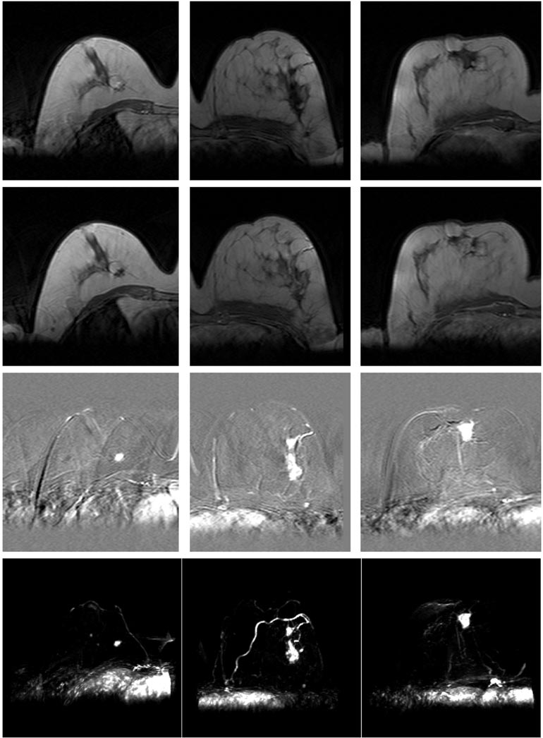
raphy volumes of 42 patients with histologically confirmed Fig. 1. Two-dimensional example slices, subtractions, and maximum intensity projections (MIPs) of subtraction volumes for three MR breast volumes. (from left to right) Patient cases 1–3. (from top to bottom) Precontrast image, postcontrast image, subtraction image, and MIP.
carcinoma, three patient cases were selected. All data were acquired on a Philips 1.5-T Gyroscan ACS2 using a fast 3-D
Ms, 35
flip angle, 350-mm field of view (FOV), and axial (transversal) slice orientation. A dynamic sequence of one scan before, and five scans after contrast injection of 0.2-mmol Gd-DTPA/kg of body weight at temporal intervals of 1 min was acquired.
For the purpose of this paper, we have selected the precontrast scan and the second postcontrast scan of the three patients.
1.48 Mm
1.48 mm (case 3), all with 4.2-mm slice thickness. From each data set, we have extracted a volumetric cuboid region of interest (ROI) containing one breast for each patient.
Both the anatomy and pathology of the selected cases are substantially different, with the overall breast volume ranging from 0.66 10 mm (case 1) to 1.23 10 mm (case 3), with
(Case 1) And 3061.75
mm (case 3). The three cases were selected because unlike the great ma- jority of cases, there was very little subject motion between ac- quisitions. This was confirmed in the visual assessment study , where nonrigid registration did not significantly improve the subtraction images for cases 2 and 3, and only improved it to a small degree for case 1 near the skin surface. Fig. 1 SCHNABEL et al.: VALIDATION OF NONRIGID IMAGE REGISTRATION USING FEMs
241
shows two-dimensional (2-D) example slices through the ROIs of the image pairs and image subtractions, as well as maximum intensity projections (MIPs) through the subtraction volumes.
From the subtraction images as well as the MIPs one can ap- preciate the negligible amount of motion between precontrast and postcontrast scans within the breast tissue, and motion arte- facts due to breathing and cardiac motion at the chest wall. The tumors and some enhanced blood vessels become clearly vis- ible within the subtraction images and MIPs. Nonrigid registra- tion confirmed almost no motion for the original image pairs: mean tissue displacements within the breast tissue, excluding the tumor region, were estimated to be within 1 mm (case 1), 0.36 mm (case 2), and 0.55 mm (case 3). Within the tumor re- gions, mean tissue displacements of 0.45 mm (case 1), 0.68 mm (case 2), and 0.40 mm (case 3) were found. Having selected image pairs with only little motion enables us to simulate motion between the original, uncorrected precontrast and postcontrast scans.
C. Model Construction
For the construction of finite-element models for the three cases, the first step is to obtain tissue segmentations. For this, the ANALYZE software package was used to segment fatty and fibroglandular tissue in the CE images. The tumors were segmented in the subtraction images, which was made possible due to the negligible amount of motion between scans.
As the second step, we have constructed for the three cases isotropic, linear, and nearly incompressible elastic models incorporating skin surface, fat, fibroglandular, and tumorous tissue. For this purpose, we have performed 3-D triangula- tions of the tumors and the overall breast tissue (excluding the tumorous tissue) using standard marching cubes and decimation techniques provided by the Visualization Toolkit , with minimal edge lengths of 4.2 mm (corresponding to the slice thickness) for tumorous tissue and 8.4 mm for the remaining tissues. Using the ANSYS FEM software package,1 the triangulations were meshed into isoparametric tetrahedral structural solids (elements), having four corner FEM nodes2 and an additional FEM node in the middle of each edge for a quadratic displacement behavior. Each FEM element was labeled corresponding to the underlying tissue type. Skin was modeled by adding 1-mm-thick triangular shell elements consisting of six FEM nodes onto the surface of the fatty tissue. The models contain 40 172 (case1), 117 436 (case 2), and 118 278 (case 3) FEM nodes, arranged in 30 841 (case 1), 89 094 (case 2), and 89 944 (case 3) elements, including the surface shells. Each FEM node has three associated degrees of freedom which define translational displacement in the
And
directions. As the third and final step in the model construction, material properties for the different tissue types were chosen from the literature. The Young’s moduli (stress–strain relations) of the different tissues were set to 1 kPa for the fatty tissue, 10 kPa for the fibroglandular tissue, and 16.5 kPa for the tumorous carcinoma . A Young’s modulus of 88 kPa was chosen for
1Available: Http://Www.Ansys.Com
2To avoid any confusion with anatomical tissue nodes in the pectoral breast region, or the B-spline control points used in the registration, we will refer to the nodes of the FEM elements as FEM nodes in the remainder of this paper.
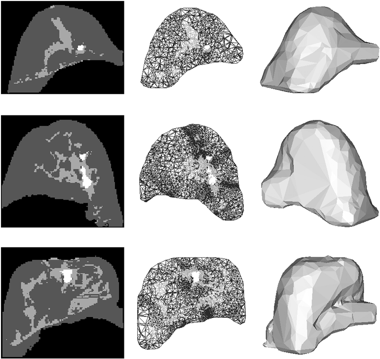
Fig. 2. Breast segmentations and FEM model renderings for patient cases shown in Fig. 1. (from top to bottom) Patient cases 1–3. (from left to right) Example slices for segmentations into fat (dark grey), fibroglandular tissue (light grey), and tumor (white); wire-frame cuts through FEM models with material labels in the same color code; mesh surface renderings of FEM models.
The wire-frame cuts show the higher mesh resolution within tumor locations. the skin, representing a linear approximation of the nonlinear stress–strain curve for abdominal skin parallel to the cranio- caudal median investigated by Park for strains up to 30%.
For near-incompressibility of the tissue, the Poisson’s ratio was set to 0.495. The aim of this study is to obtain approximate breast models which can produce physically plausible deformations, rather than to build optimal, patient-specific models. This allows the generation of a generic image class for registration val- idation. For more realistic breast modeling, patient-specific model parameters would need to be determined from in vivo elastographic measurements. However, the models described above can be varied further with respect to material properties, nonlinear or even anisotropic tissue characteristics, in order to simulate different patient characteristics. Fig. 2 shows example slices through the tissue segmentations, material-labeled wire- frame renderings as well as surface renderings of the three breast models.
A. Finite-Element Model Solutions
In a previous study involving radiologists, it was found that due to the confinement of the breast within the scanner RF coil, tissue motion of up to 15 mm in extreme cases was observed be- tween the acquisition of precontrast and postcontrast image vol- umes , but for the great majority of the cases deformations were found to be 10 mm or less. Consequently, FEM boundary conditions using initial surface displacements of approximately 10 mm were applied to the three models presented above. The models were subsequently solved using a preconditioned con- jugate gradient solver of the ANSYS FEM package. To each
242
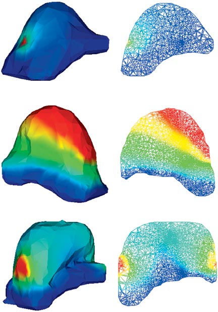
Fig. 3. Surface and wire-frame renderings of example solutions for models shown in Fig. 2. (from top to bottom) Patient cases 1–3, for point puncture (case 1), regional displacement (case 2), and two-sided contact (case 3). (left) Surface renderings of deformed meshes. (right) Wire-frame cuts through deformed meshes. Deformation magnitudes are mapped using rainbow color coding, with dark blue corresponding to 0 mm, and dark red corresponding to 10-mm deformation magnitude.
breast model, the following four deformation types character- istic for real patient acquisitions were applied. • Regional displacement simulates a uniform surface dis- placement by translating a set of surface FEM nodes.
• Point puncture displaces a single surface FEM node which simulates a very localized displacement, e.g., as occurring during a biopsy without any breast fixation.
• One-sided contact displaces surface FEM nodes on one side onto a plane, which simulates the deformation of the breast when moving against the scanner RF coil, assuming no sliding on the plane itself.
• Two-sided contact analogously models the deformation when the breast is fixed at both sides, by displacing sur- face FEM nodes onto a plane on each side.
Thus, we have obtained 12 deformation simulations (three breast models with four deformation simulations each). For more exhaustive deformation simulations, additional simula- tions can be performed by varying the type, magnitude, and locality of the boundary conditions. In all simulations, the FEM nodes adjacent to the deep pectoral fascia have been fixed, assuming no movement of the pectoral muscle and pectoral fascia. Fig. 3 shows surface renderings of and wire-frame cuts through the patient models for example FEM solutions, with local deformation magnitudes mapped in rainbow color coding.
At Each Fem Node Within The Model. The Average
displacement of the whole breast volume and within individual tissue compartments can be obtained by integrating over all
Where
is the number of FEM nodes in the model or of indi- vidual tissue compartments.
Not
coinciding with a FEM node location, but lying anywhere within a FEM element, a numerically exact displacement can be in- terpolated by weighting the element’s ten FEM node displace-
(3)
Hence, a dense displacement interpolation for all image voxels can be obtained, and integrated over all voxel locations within the breast volume or within individual tissue compartments to
Where
is the number of voxels over which this measure is computed. Fig. 4 shows the average and maximum node and interpolated voxel displacements for all patient solutions within the whole breast volume as well as only within the tumorous tissue. The maximum displacements are around 10 mm, mostly occurring in fatty tissues close to the skin surface. A higher mean displace- ment within the tumors occurs for cases 2 and 3, where the tu- mors are located close to the initially displaced skin surface.
C. Interpolation Of Fem Solutions
In order to simulate deformation in the images for registration application, the images need to be transformed using the dense displacement field obtained from each of the FEM solutions.
In earlier work , we have used a scattered data interpola- tion technique by Lee et al. based on a multilevel B-spline hierarchy whose sum approaches the desired interpolation, and which can be reformulated into one equivalent B-spline interpo- lator. One advantage of using such an interpolator is that simu- lated deformations within the finite-element mesh can be appro- priately blended off at the mesh surface and, thus, discontinu- ities in the deformation field can be reduced. This is particularly important if the mesh surface, due to triangulation and decima- tion, has relaxed and may not fully fit the original breast volume.
The major disadvantage of this approach, however, is that due to the approximating nature of B-splines, a small residual error at the FEM node locations may remain, and that a favorable bias toward spline-based registration techniques could be intro- duced.
Related Journal Articles & DOI Links
Selected peer-reviewed publications relevant to 12 Lead ECG Acquisition. Click the DOI to access the full paper (may require institutional access).
-
1. Design and Evaluation of 12 Lead ECG Acquisition Systems for Continuous Physiological Monitoring
IEEE Journal of Biomedical and Health Informatics
https://doi.org/10.1109/JBHI.2020.2981234 -
2. Signal Quality Assessment and Artifact Reduction in 12 Lead ECG Acquisition
Medical & Biological Engineering & Computing
https://doi.org/10.1007/s11517-020-02145-6 -
3. Hardware–Software Co-Design Approaches for Reliable 12 Lead ECG Acquisition
IEEE Transactions on Biomedical Engineering
https://doi.org/10.1109/TBME.2019.2895762 -
4. Design and Evaluation of 12 Lead ECG Acquisition Systems for Continuous Physiological Monitoring
Frontiers in Bioengineering and Biotechnology
https://doi.org/10.3389/fbioe.2020.00123 -
5. Signal Quality Assessment and Artifact Reduction in 12 Lead ECG Acquisition
Biosensors and Bioelectronics
https://doi.org/10.1016/j.bios.2021.112345 -
6. Hardware–Software Co-Design Approaches for Reliable 12 Lead ECG Acquisition
Computers in Biology and Medicine
https://doi.org/10.1016/j.compbiomed.2021.104567 -
7. Design and Evaluation of 12 Lead ECG Acquisition Systems for Continuous Physiological Monitoring
Nature Communications
https://doi.org/10.1038/s41467-020-12345-6
Why Choose Us?
Bangalore guidance for robotics, Spectre and autonomous systems projects.
Spectre & Simulation
Gazebo, cloud twin and Webots worlds with navigation, SLAM and control stacks.
Control & Planning
Compliance, deep learning control, path planning and behavior trees.
Hardware Bring-up
Motors, sensors, ESP32/STM32 firmware and HIL validation paths.
Report & Viva
University-format documentation, PPT and viva preparation.
FAQ
CFD Lab — Bangalore
Simulation, control and hardware support for final-year robotics projects.
Stacks
Worlds
Digital Twin
Control
Robots
Offline
Bring-up