Received May 4, 2020, accepted May 17, 2020, date of publication May 25, 2020, date of current version June 5, 2020. Digital Object Identifier 10.1109/ACCESS.2020.2997605
Bing Jia2, And Shengzhang Wang1,5
3Shanghai Engineering Research Center of Heart Valve, Shanghai 200032, China This work was supported in part by the National Natural Science Foundation of China under Grant 11872152, Grant 81801844, and Grant 81873501, and in part by the Fudan Affiliated Zhongshan Hospital Young Elite Program under Grant 2019ZSYQ05.

ABSTRACT The objective of this study was to evaluate the clinical effectiveness of surgical reconstruction of aortic valve using autologous pericardium, and the hemodynamic impact of matching the circumferential direction of the trimmed leaflet to inherent fiber orientation of the pericardium during surgery. A patient specific aortic valve model was built based on CTA data. The reconstructive surgery was carried out on the model following normal operating procedures. FSI simulation was performed to analyze the hemody- namic characteristics among the diseased model, normal model and three operative models with different misaligned angles between the circumferential direction of the substitute and inherent fiber orientation. The differences of EOA, velocity distribution, stress and strain on leaflets, and the valve deformation between the five models were compared and analyzed. The results showed that reconstructive surgery helps enlarge EOA, reduce abnormity of leaflet motion and blood ejection compared to diseased model. There was no significant difference between operative models with different misaligned angles in terms of leaflet motion and flow pattern, but as the misaligned angle increased, greater strain and deformation were observed on leaflets during the diastolic period. The present study demonstrated the instant clinical effectiveness of the reconstructive surgery of aortic valve by the improvement of EOA and flow pattern, and suggested that during the operation it may be unnecessary to match the circumferential direction of the substitute to inherent fiber orientation of the pericardium since the hemodynamic characteristics were insensitive to the fiber alignment, but the strain and deformation increment on the substitutes during diastolic period still raised concern about their durability.

INDEX TERMS Aortic stenosis, aortic valve reconstruction, medical imaging, fluid-structure interaction.
I. Introduction
The aortic root comprises of three important structures, namely aortic sinus, leaflet, and aortic annulus. The aortic sinuses are three anatomic dilations on ascending aorta right above the aortic valve, which allows the continuous blood supply to coronaries and help form vortices that assist the motion of aortic valve. The aortic valve incorporates three The associate editor coordinating the review of this manuscript and approving it for publication was Gina Tourassi.

flaps called leaflets or cusps, which can be pushed open from the ventricle side to allow blood flow and closed together to prevent backflow. The aortic annulus is a crown-shaped fibrous ring at the aortic orifice, which is part of the fibrous skeleton of the heart and connecting the leaflets. Aortic steno- sis usually relates to the abnormality of the aortic ring and leaflets, which makes them clinically significant during the surgery , . The anatomical morphology of each part of the aortic root and the coordinated changes during the cardiac cycles are the keys to its normal functioning , .

Volume 8, 2020
This work is licensed under a Creative Commons Attribution 4.0 License. For more information, see https://creativecommons.org/licenses/by/4.0/
97343
Y. Feng et al.: Computational Modeling for Surgical Reconstruction of Aortic Valve Pathological conditions such as congenital aortic stenosis, aortic sclerosis, leaflet thickening, etc. can cause varying degrees of damage to the function of the aortic valve.

The surgical therapies for the aortic valve diseases have been developed over decades, and replacement of aortic valve is one of the most important treatments today. Though mechanical valve and bio-prosthetic valve are recommended and widely used for aortic valve replacement in parts of patients especially for elder people, the high failure rate is still impeding their use for young adults and children. What’s more, currently there is no matched artificial valve graft for children and infant patients. In recent years reconstructive surgery of aortic valve by using autologous pericardium was well developed with positive outcomes, which brings hopes to the patient population. The reconstructive surgery named AVNeo (Aortic Valve Neocuspidization) procedure was ini- tiated by Ozaki – and broke through the traditional surgery contraindications like endocarditis, and there was no need for long term anticoagulation after surgery. Up to date Ozaki has treated more than 850 adult patients using the surgery with satisfactory mid-term outcomes. The recon- structive surgery of aortic valve was introduced to China gradually developed into a unique operation for children and infant patients. Although the treatment has been carried out worldwide with more than 2000 cases, the operative tech- niques have not been standardized yet and the clinical effec- tiveness also needs more verification. For instance, currently the clinicians do not pay much attention during dissection and substitute preparation to match the circumferential direction of the trimmed leaflets to the inherent fiber orientation of pericardium, and the impact of such misalignment to the hemodynamic characteristics of the repaired aortic valve and clinical outcomes still remain unknown.

ALE (Arbitrary-Lagrangian-Eulerian), SPH (Smoothed Particle Hydrodynamic), and IBM (Immersed Boundary Method) are currently the three most popular methods to deal with the FSI (fluid-structure interaction) problems for hemodynamic studies. ALE and SPH methods are usually used to study blood flow within cardiovascular vessel and its interaction with rigid body movements such as mechanical valve –. However, the instability of adaptive remesh- ing algorithm, high calculation expense, and tedious defini- tion process, limit their use for simulation of bio-prosthesis valve , which involves complex contact and FSI problem during transient calculation. IBM method was introduced by Peskin in 1972, in which the compatibility require- ment for the fluid and structure interfaces could be waived by translating the interaction between the two materials to penalty forces, and applied to the nodes near the interface.
Ma Et Al. , Et Al. Meschini , And Et Al. Luraghi
have been using the IBM method to study the hemodynamic characteristics of the tricuspid valve, mitral valve, and other allografts. However, the implementation of the method on simulation for reconstructive surgery of aortic valve is rarely reported.

In this context, we aim to build an FSI model for studying and evaluating the effectiveness of reconstructive surgery of aortic valve and potential refinement on operative techniques.

In particular, we (i) built a patient specific aortic root model, (ii) perform the aortic valve reconstructive surgery using autologous pericardium on the FE model following stan- dard procedure, (iii) made the comparison of hemodynamic characteristics between diseased model, normal model, and operative models, (iv) demonstrated the robustness of recon- structive surgery of aortic valve, as well as the feasibility of using FSI method for simulation of surgery, which allowed getting more reliable and exhaustive information about the heart valve behaviors.
A. Patient Specific Aortic Valve Model
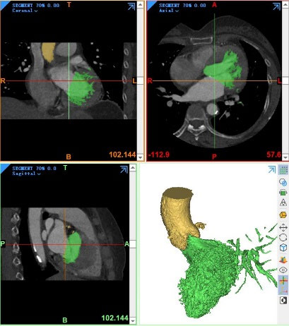
In present study, due to the limitation of imaging equipment and technology to capture small and fast-moving structures, imaging data from an adult patient was used instead of chil- dren. Hence a 63-year-old female patient, who suffered from aortic valve thickening and calcification with moderate to severe aortic regurgitation and mild stenosis, was included in our study. The patient specific cardiac coronary CTA images were obtained from Zhongshan Hospital Affiliated to Fudan tem (Canon Medical Systems, CA, USA). The 3D anatomy of the aortic root was reconstructed from CT images into STL (stereolithography) format using Mimics software (Version 21.0, Materialise, Leuven, Belgium). The advanced CT Heart module was used to facilitate the segmentation of aortic root and valve, Hounsfield unit was manually set between 218 to 1859 to better identify the detail of heart structure and get appropriate segmentations for the different soft tissues.

Smoothing and wrapping processes were also applied to the models to mitigate the impact of images noise. Then the STL model of the aortic valve was then imported to Geomagic Studio software (Version 12.0, Cary, North Car- olina, USA), in which the redundant arteries were trimmed from aortic, ventricular and coronary ends by three different planes that perpendicular to the central line of the vessels, leaving only the ROI (Region of interest) of aortic root includ- ing aortic sinus and valves.

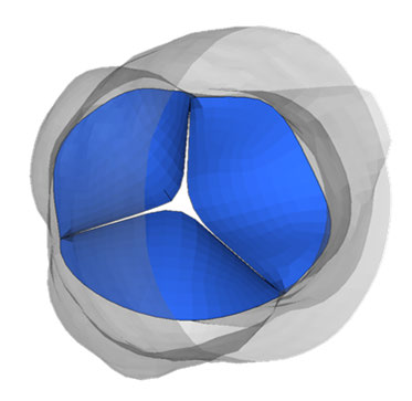
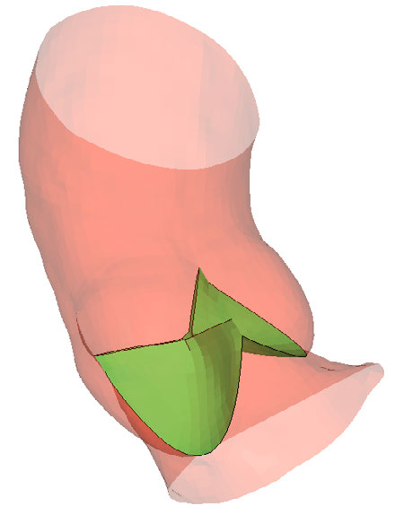
In order to simplify the simulation and reduce the calcu- lation burden, all the vessel walls and leaflets were repre- sented by 3D shell elements with different thickness in our study. Hypermesh (Altair Engineering, Inc., Troy, Michigan, USA) was hereby used to re-mesh the model with first order quads, nodes on aortic sinus and root of leaflets were merged (Figure 1.a).
B. Normal Aortic Valve Model
Morphological abnormalities of aortic root were believed to affect the normal motion of the aortic valve . In the patient specific diseased model, the LC (left coronary) sinus and the NC (non-coronary) sinus were found excessively bulged near
Volume 8, 2020
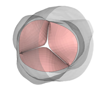
Y. Feng et al.: Computational Modeling for Surgical Reconstruction of Aortic Valve FIGURE 1. (a) FSI model of the diseased patient specific aortic valve; (b) Normal model built with aortic root reduction and annulus smoothing.

the root, and the aortic annulus that attached with LC and NC leaflets in these two sinuses were deformed and dilated either (Figure 1.b). Hence based on the anatomical knowledge of healthy aortic root, a normal model was built as a benchmark for comparison, with a few anatomical abnormities fixed from the patient specific model. Geomagic and Hypermesh software were hereby used to reduce the bulged LC and NC sinuses, smooth the relative aortic annulus and make them in normal shape.
C. Aortic Valve Reconstructive Surgery Model
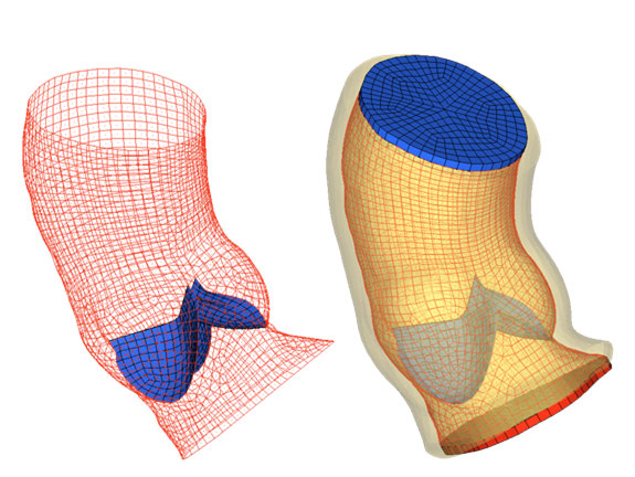
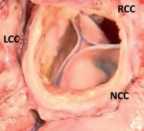
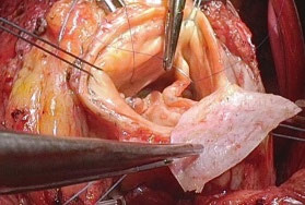
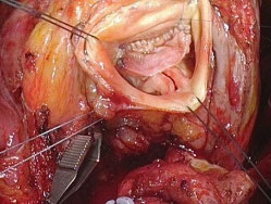
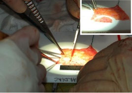
According to the anatomical experiments and clinical stud- ies, the unpressurized aortic valves are usually in a closing position and considered as in stress-free state or the initial condition for heart valve FSI studies –. During the aortic valve reconstructive surgery, the clinicians also trim the planar substitutes from the autologous pericardium, dissect the native leaflets, sew the substitutes to the aortic annulus, then fix them in a closing position as initial state , , (Figure 2a).

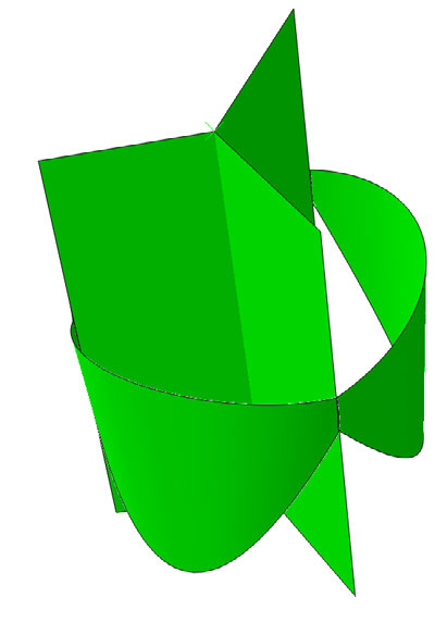
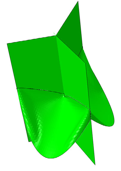
Following the standard operative procedure, in present study the surgical reconstruction of aortic valve was simu- lated on the silico model by using ABAQUS standard soft- ware (Version 2017, Dassault System, Vélizy-Villacoublay, France). Firstly the mesh of three native leaflets was removed from the patient specific model. Secondly three scallop shape substitutes were cut from a flat surface, wrapped and merged to the aortic annulus and commissure area of the aortic model.
The three newly created cuspids were fixed on the root and commissure area, and a mild pressure of 0.6 KPa (≈4% of the normal maximum transvalvular pressure) was applied to the three cuspids from aortic side on the belly area to make them gently contact the virtual planes built in the middle of the aorta as stopping position. Finally the aortic root model FIGURE 2. (a) Surgical reconstruction of Aortic valve; (b) Simulated AVNeo surgery; (c) Illustration of misalignment between circumferential direction of substitute and inherent fiber orientation of pericardium.
FIGURE 3. Ventricular pressure (Pv) and aortic pressure (Pao) waves applied to the inlet and outlet of the FSI model. with the leaflets in closing position was used as the initial state for the simulation of aortic valve reconstructive surgery (Figure 2b).
D. Materials
Either normal aortic valve or fibrous pericardium comprises multiple layers of soft tissues and is reinforced by collagen fibers along specific directions. In native leaflets the fiber and bundle orientation usually match the circumferential direc- tion , while in native pericardium the fibers or fibrils of collagen are aligned predominantly in the horizontal direction that perpendicular to the base-apex axis of the heart .
The mechanically anisotropic behavior of the two materials have been proven by various in-vitro tests, and in present study the leaflets were also considered to be orthotropic materials, the properties of the native valve and pericardium were taken from the work of Grande-Allen et al. and Luo et al. respectively, detailed properties were listed in table 1. To define the local orthotropic material for each leaflet, a v-vector was given along with the centerline of the aortic vessel, and the preferred direction of the material for
97345
Y. Feng et al.: Computational Modeling for Surgical Reconstruction of Aortic Valve FIGURE 4. Top views of the aortic valve kinematics at six different moments in one cardiac cycle. From top to down are the diseased model, normal model, 0◦misaligned (ideal) model, 45◦misaligned model, and 90◦misaligned model.
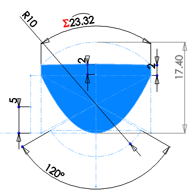
TABLE 1. Properties of the leaflets used in this study. each element of the leaflet was determined by the v-vector cross-product of the normal vector of that element. The aortic root was also assumed to be orthotropic and defined with the same scenario.
The property of native valve was applied to diseased model (patient specific aortic valve model) and normal aortic valve model. And to simulate the arbitrary dissection dur- ing AVNeo surgery and potential misalignment between the circumferential direction of the substitute and the inherent fiber orientation of the native pericardium, the pericardial FIGURE 5. EOA changes of the five different models throughout the systolic period.
property was then applied to the three operative models, with BETA angle defined which indicates the material offset angle from the preferred orientation. For the ideal model, the circumferential direction of the substitute was defined 0◦deviated from the fiber orientation of the pericardium which the same as native valve; as for the other two mod- els, the circumferential directions were defined 45◦and 90◦ deviated from the fiber orientation, which were as shown in Figure. 2c.
The blood was assumed to be Newtonian fluid with density of 1050kg/m3 and dynamic viscosity of 0.00035 Pa·s. In order to reduce the simulation time, the speed of sound was set to 150m/s according to Lau’s proposal .

Volume 8, 2020
Y. Feng et al.: Computational Modeling for Surgical Reconstruction of Aortic Valve FIGURE 6. Velocity distribution and streamlines on a plane passing through the centerline of the valve at five different moments.
E. Ibm Method And Fsi Models
The FSI simulations were performed using explicit solver of LS-DYNA (Version R11.1.0, LSTC, Livermore CA, USA and ANSYS, Inc., Canonsburg, PA, USA) on an Intel Xeon server of 2.8GHz with two E5-2680 Xeon CPUs (20 proces- sors) and 32G RAM.

In this study the immerse boundary method was used to deal with the interaction between blood flow and the aortic sinus/valve. In brief, by using the IBM method, the fluid domain could be treated as static structural grid, and the solid domain would be directly embedded into the fluid parts and move without compatibility requirement for the mesh on fluid-structure interface. Instead of matching interface, the solver will search the penetration changes of the solid meshes into the fluid meshes during simulation, then apply elastic reaction forces to the nodes of solid domain, and try to push them back to their original positions using the penalty-based coupling approach. Mass and momentum of the structural nodes are also re-allocated to surrounding fluid nodes by weight, and coupling the velocity and acceleration between two domains. Detail information could be found in references , .
The fluid domain comprised of three parts, including con- trol volume, inlet and outlet compartments. The control vol- ume was a solid column with greater diameter than the aortic root, and bent along the direction of the aortic vessel. The two ends of the control volume laid on the same trimming planes of aorta model. The inlet and outlet compartments were two thin layers of mesh extended from the control volume, and matched the two ends of the aorta model.

As the boundary condition for the solid domain, the two ends of the vessel were fixed in all directions. While for the fluid domain, the outer surfaces of the three parts were fixed.

The normal left ventricular and aortic pressure profiles were obtained from the literature , and scaled up to the patient specific pulsating blood pressure based on the measurement data recorded during the surgery, then applied to the inlet and outlet compartments individually.

In order to deal with the complex contact of the three cuspids during the valve open and close, an automatic
Related Journal Articles & DOI Links
Selected peer-reviewed publications relevant to 12 Lead ECG Acquisition. Click the DOI to access the full paper (may require institutional access).
-
1. Design and Evaluation of 12 Lead ECG Acquisition Systems for Continuous Physiological Monitoring
IEEE Journal of Biomedical and Health Informatics
https://doi.org/10.1109/JBHI.2020.2981234 -
2. Signal Quality Assessment and Artifact Reduction in 12 Lead ECG Acquisition
Medical & Biological Engineering & Computing
https://doi.org/10.1007/s11517-020-02145-6 -
3. Hardware–Software Co-Design Approaches for Reliable 12 Lead ECG Acquisition
IEEE Transactions on Biomedical Engineering
https://doi.org/10.1109/TBME.2019.2895762 -
4. Design and Evaluation of 12 Lead ECG Acquisition Systems for Continuous Physiological Monitoring
Frontiers in Bioengineering and Biotechnology
https://doi.org/10.3389/fbioe.2020.00123 -
5. Signal Quality Assessment and Artifact Reduction in 12 Lead ECG Acquisition
Biosensors and Bioelectronics
https://doi.org/10.1016/j.bios.2021.112345 -
6. Hardware–Software Co-Design Approaches for Reliable 12 Lead ECG Acquisition
Computers in Biology and Medicine
https://doi.org/10.1016/j.compbiomed.2021.104567 -
7. Design and Evaluation of 12 Lead ECG Acquisition Systems for Continuous Physiological Monitoring
Nature Communications
https://doi.org/10.1038/s41467-020-12345-6
Why Choose Us?
Bangalore guidance for robotics, Spectre and autonomous systems projects.
Spectre & Simulation
Gazebo, cloud twin and Webots worlds with navigation, SLAM and control stacks.
Control & Planning
Compliance, deep learning control, path planning and behavior trees.
Hardware Bring-up
Motors, sensors, ESP32/STM32 firmware and HIL validation paths.
Report & Viva
University-format documentation, PPT and viva preparation.
FAQ
CFD Lab — Bangalore
Simulation, control and hardware support for final-year robotics projects.
Stacks
Worlds
Digital Twin
Control
Robots
Offline
Bring-up