Role Of Leaflet Geometry
B. Kaoui,1, ∗A. Bou Orm,1 P. Navet,1 J. Baish,2 and L.L. Munn3
1Biomechanics And Bioengineering (Umr 7338),
Centre National de la Recherche Scientifique and Universit´e de Technologie de Compi`egne,
Lewisburg, Pa 17837, Usa
Massachusetts General Hospital and Harvard Medical School,
(Dated: April 14, 2026)
Bicuspid valves with crescent-shaped leaflets are found in lymphatic vessels and veins, where their primary function is to prevent reflux and ensure unidirectional flow toward the heart. These valves are passive, and their functionality emerges spontaneously from a complex interplay between the properties of the valve leaflets and the flow patterns developing within the vessel sinus region surrounding the valve. The main function of the valves is to limit retrograde flow, or reflux, but the optimal valve structure has not been well-characterized. Here we investigate numerically how the length of the leaflets affects the valve efficiency in preventing reflux. The valves are subjected to backward flow, akin to that imposed by gravity. We report the flux through the valve orifice as a function of key parameters: valve length, leaflet length, and leaflet rigidity. We monitor the transition in the flow regime - from reflux to complete flow blockage - by varying only the leaflet length.
The transition threshold is found to depend strongly on the valve shape and stiffness. We captured these control parameters numerically to evaluate the ability of the valve to close and prevent reflux.
This study allowed us to explain reflux observed experimentally in certain incompetent abnormal and immature valves, particularly those with shorter leaflets. arXiv:2604.11776v1 [physics.flu-dyn] 13 Apr 2026
Introduction
The lymphatic system consists mainly of a ramified network of lymphatic vessels (lymphatics), where lymph fluid is drained from the interstitial tissue by the initial lymphatic capillaries, transported by larger collecting lymphatic vessels, filtered by lymph nodes, and then re-injected back into the thoracic duct and the subclavian veins to reintegrate with the blood circulation . Other organs, in addition to the vessels, are part of the lymphatic system, such as the lymph nodes, the thymus and spleen. While the heart serves as the central pump that pushes blood throughout the cardiovascular system, pumping in the lymphatic system is achieved locally at the level of the lymphangion, the vessel segment delimited by two flanking valves. What is intriguing about this process is the presence of a series of valves along the vessels that guarantee unidirectional flow. Each valve opens to allow forward flow, toward the heart, and closes to prevent retrograde flow. This occurs spontaneously without any external control . Biological valves, including lymphatic and venous valves, are passive structures by default. They deform and adapt their configuration in response to the surrounding flow and vessel deformation. The objective of our present study is to examine the details of the closure mechanisms of bicuspid valves, which are composed of two crescent-shaped leaflets, as found in the lymphatics and blood veins, when subjected to backward flow. We aim to extend and complement previous studies that address the open question: What determines the efficiency of bicuspid valve closure during retrograde flow? In the present study, we investigate this question with a specific focus: How do leaflet mechanics and geometry affect closure efficiency? We address this question for valves of various lengths, and stiffness. To the best of our knowledge, this aspect is being explored for the first time. In this work we address an open question in biology and evolution by combining multiphysics simulations with a physics-based approach to analyze fluid–structure interactions and valve mechanics. In particular, we investigate a fundamental and still unresolved question: Why has nature produced valve leaflets with a crescent shape? Several aspects of valve geometry have already been treated in the literature. The effects of valve length and stiffness are relatively well understood: increasing valve length amplifies hydrodynamic resistance, while excessive stiffness hinders proper valve closure. However, a crucial question remains largely unexplored and is highly intriguing from both a biological and physical perspective: Why is the leaflet crescent-shaped, and to what extent should the valve leaflet be creased or curved to achieve optimal performance?
In Other Words, What Is The
functional role of the cusp geometry beyond simple valve length and stiffness considerations? Most experimental studies on lymphatic vessels are biology oriented. Few studies have addressed the challenging in vivo and in vitro details of the fluid mechanics of the problem, and how fluid forces interplay with the valve mechanics, which is of interest to us. The most relevant study is by Munger et al., who investigated the molecular mechanisms underlying lymphatic valve development and its effect on valve leaflet length, and thus, on the overall valve function. They have examined the effect of Connexin43 (Cx43), which is an essential protein for gap junctions between lymphatic endothelial cells. The authors used genetically modified mice to assess the consequences of Cx43- specific deletion in the lymphatic system and its role in lymphatic valve development and function. They demonstrated that Cx43 deletion in endothelial cells severely impairs valve development, resulting in the overall inability of the valves to prevent reflux. As a result, this disruption can give rise to pathologies such as chylothorax. On a molecular level, the study identifies Cx43 as a critical component for cell signaling and coordination among lymphatic endothelial cells. The results reveal a reduced number of functional valves in mutant mice, exhibiting structural disorganization and defects in morphogenesis, primarily manifesting as valves with short, underdeveloped leaflets that fail to achieve unidirectional flow. Another recently published work presents high-quality 3D images of developing lymphatic valves by categorizing valvulogenesis into four distinct stages . Each stage is defined by the growth and extension of the valve leaflets within the vessel. At early stages of development, when the leaflet starts taking shape, they are not able to prevent reflux. It is not until later stages of development that the mature valve acquires fully developed, long leaflets that can block reflux efficiently.
Computer simulations are used to gain a deeper understanding of the details of valve function and lymphatic vessels, which are not accessible through in vivo, or even in vitro experiments [2, 3, 9].
Only A Limited Number
have analyzed valve dynamics systematically using three-dimensional simulations . The most relevant to our study is by Ballard et al. , who studied the effect of lymphatic valve overall length on its dynamic behavior and function. Their simulations focused on the effect of valve length and bending rigidity on valve efficiency. The results indicate that, for valves of given elasticity, the overall valve length should be short to optimize forward flow, but long to prevent backflow. Indeed, morphological abnormalities or excessive valve rigidity result in inefficient reflux blockage, which is characteristic of pathological conditions. The study also highlights mechanisms that may explain valve malfunctions observed in certain pathologies, such as lymphedema, where valves exhibit excessive rigidity or deformability. Although their simulations were also conducted in a straight, rigid vessel, similar to our setup, they did not investigate the role of leaflet length, which is a central focus of the present work. The authors developed a model based on a coupled fluid-structure approach. Flow dynamics of the lymph were computed using the Lattice Boltzmann Method (LBM) , while the mechanics of the valves were evaluated with the Lattice Spring Method (LSM) . These two numerical methods are also employed in our work, in addition to the Immersed Boundary
3
Method (IBM) for the two-way fluid-structure interaction part . The effect of leaflet length has also been investigated, but in a different context, heart valve implantation. Hof- ferberth et al.
proposed an approach conceptually related to our current study on lymphatic valves.
Their
work focuses on artificial cardiac valves and introduces a geometrically adaptable prosthetic valve that can alter its shape in response to pressure and flow variations. Traditional heart valve implants often suffer from anatomical compatibility issues, particularly in patients with complex or atypical geometries. Such mismatches can lead to com- plications, including paravalvular leakage, suboptimal hemodynamic performance, or increased risk of calcification.
To address these challenges, the authors designed an innovative valve featuring a self-expanding frame and a flexible leaflet structure that together enables patient-specific geometric adaptation. Preclinical animal studies demonstrated a substantial reduction in paravalvular leakage owing to the improved anatomical conformity. This work builds on an earlier numerical study by Hammer et al. , who evaluated the performance of bileaflet valves with varying leaflet lengths under progressive vessel dilation. Their aim was to model conditions encountered during pediatric growth, where repeated valve replacements are required to match the enlarging cardiovascular anatomy. Hammer et al. showed that valves with longer leaflets retain the ability to prevent regurgitation even beyond certain degrees of vessel diameter expansion. However, their approach did not explicitly account for fluid dynamics or fully coupled fluid–structure interaction (FSI), both of which are incorporated in the present study.
L
!"##"$%1)'2",".
Fig. 1.
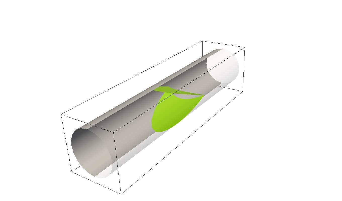
Schematic illustration of the numerical set-up (left panel), consisting of a straight, rigid vessel of circular cross-section enclosing a flexible one-way bi-leaflet valve similar to those found in lymphatic vessels and veins featuring crescent-shaped leaflets (right panel).

We complement these previous studies by examining the effect of valve leaflet length, also referred to as cusp length or midline length, on valve performance to close and to prevent reflux. We would like to avoid any confusion and clarify that the leaflet length e is not the overall valve length L, see Fig. 1. In the present study, varying the leaflet length along its centerline corresponds to changing the extent to which the leaflet is scalloped at its center, holding fixed the leaflet angle and line of attachment along the vessel wall. By using leaflet length as a control parameter, we capture the transition from partial reflux to complete flow blockage. The critical length at which this transition occurs depends on both valve stiffness and geometric shape parameters. In the following sections, we present our computational setup, the methodology, and the resulting flow regimes summarized onto state diagrams. Comparisons are made with the available numerical and experimental studies.

Problem Statement
The mechanism of valve closure, induced solely by backward flow, has been the subject of numerous studies in the literature. This topic is of particular concern to clinicians due to its association with conditions such as lymphedema in lymphatic vessels and varices in veins. From a mechanical perspective, the problem may seem straightforward: the leaflet closes in response to backward flow and subsequently blocks the flow. However, the shape, flexibility, and attachment of the leaflet to the vessel wall, as shown in Fig. 1, play a complex and nontrivial role in achieving spontaneous valve closure . The ability of the valves to open under forward flow and close under backward flow has been linked to the flow pattern that occurs in the vessel sinus region, which encloses the valve. Some authors
4
have proposed that the primary mechanism of valve closure involves vortices generated within the sinus region, which act to push the two leaflets together to seal and close [23, 24]. However, it remains unclear which factors – valve shape, vessel geometry, or fluid dynamics – are primarily responsible for the valve’s ability to close effectively. These questions remain and have been explored by researchers in various disciplines, including biology, fluid mechanics, medicine and biomedical engineering. Interestingly, this question has been studied for over five centuries, dating back to Leonardo da Vinci’s early analysis of the flow patterns around heart valves .

In our present study, we investigate how the shape and elastic properties of the valve leaflets influence the ability of the valve to prevent reflux during imposed backward flow, while maintaining the vessel wall in a straight and rigid configuration (see Fig. 1). The flow regime is given by the dimensionless vessel-based Reynolds number defined as,
(1)
where D is the vessel diameter, ν is the fluid kinematic viscosity, and U the maximum flow velocity at the vessel axis in the absence of the valve. Re is varied within a small range, less than or equal to unity (Re ≤1) to model laminar flow in which viscous forces dominate over inertial forces, as found in real lymphatic vessels. With these assumptions, we aim to isolate two key parameters, the valve elasticity and shape, as the primary contributors, while excluding the effects of inertia, sinus region, and vessel dynamics at this stage. We report on how the valve geometry, particularly leaflet length (cusp length), and mechanical properties restrict reflux.

Model And Methodology
We use computer simulations to conduct an extensive parametric study. Our simulations are fully three-dimensional and account for the two-way FSI between the valve dynamics and the fluid flow. The valve consists of two initially flat crescent-shaped leaflets, as illustrated in Fig. 1. They are mathematically assumed to be of zero thickness. To model the effect of gravity in a limb when a person is in a vertical standing posture, the flow is applied in the backward direction, opposite to x-direction, by exerting a constant, uniform body force on the fluid. The valve has a projected length L, while each leaflet has a projected length or elongation e, measured at its midline. L and e are not the actual lengths, but rather the projections on the x-y plane, as shown in Fig. 1. In this framework, the absence of a valve corresponds to e = 0, whereas a fully extended valve, with a flat edge line, corresponds to e = L. The leaflet’s free-moving edge is defined by a parabola. The leaflet rigidity κ in our study is uniform and arises from the resistance of the valve to three deformation modes : stretching-compression, shear and bending, with rigidities set to be of the same value to ensure that none of the three deformation modes becomes artificially dominant in our simulations.

They therefore contribute with comparable intensities and to reduce the problem’s mechanical parameters to a single parameter. We use the associated stiffness dimensionless number,
(2)
obtained by making the Navier-Stokes equations, with the forcing term, dimensionless (see Appendix A). η is the dynamic viscosity of the fluid. The parameter K controls the valve’s overall rigidity. Higher values correspond to stiffer valve leaflets, and lower values to softer ones. We approach the problem from a fluid mechanics perspective, disregarding biochemical signaling [4, 6, 22], and focusing solely on the resulting flow patterns and their interaction with the valve.

The simulations rely on a combination of three complementary numerical methods : i - the Lattice Boltzmann Method (LBM) used to compute the fluid dynamics . LBM is particularly well-suited for predicting flow in com- plex geometries, such as those found in porous media, microfluidic devices, and lymphatic and cardiovascular vessel networks. It is also compatible with parallel computing due to its localized nature, allowing for faster simulations; ii - the Lattice Spring Method (LSM) employed to recapitulate the elasticity of valve leaflets [18, 26]. This approach enables the modeling of deformable structures in a simple manner, without resorting to a more sophisticated combi- nation of continuum solid mechanics and finite element methods; iii - the Immersed Boundary Method (IBM) used to achieve the two-way coupling of FSIs . It represents effectively how lymph flow deforms the valve leaflets and, in turn, how these deformations perturb the surrounding flow. The computer code developed for this study is openly accessible via a GitLab repository .

Fig. 2.
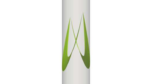
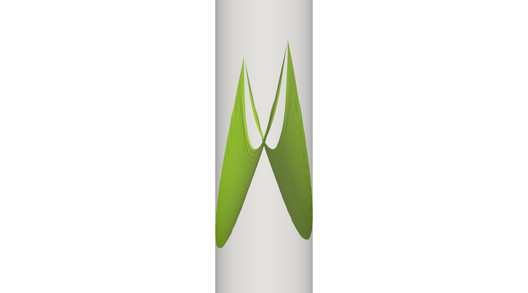
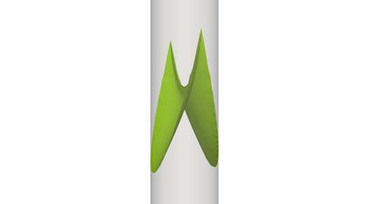
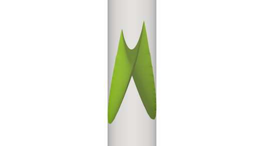
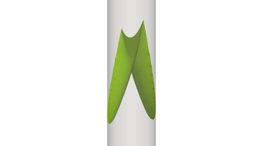
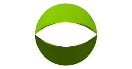
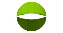
(top panel) Top view of the resting shape of valves of the same length (L = 2D), but with varying leaflet midline lengths e. (middle panel) Semi-profile view of the corresponding deformed shapes in the steady regime under backward flow, slightly rotated to better display leaflet deformation. (bottom panel) Frontal view showing that valves with shorter leaflets form a wider open orifice, which fails to prevent reflux, whereas valves with longer leaflets close completely and thus successfully block reflux.

Valve Closure Performance
The initial and equilibrium shape of the leaflets is assumed to be flat and crescent-shaped. The applied flow is steady and driven by a uniform body force. All the results shown in the following figures are obtained at Reynolds number Re = 1. After a transient numerical phase, the valve reaches a steady configuration with a shape that depends on the elastic and geometric properties of the leaflets. Figure 2 shows the steady-state shapes adopted by valves of the same length (L = 2D), but with varying leaflet lengths e. Valves with longer leaflets develop a curved closed shape when exposed to backward flow. In contrast, valves with shorter leaflets fail to effectively block lymph flow, allowing fluid leakage through their wide open orifice. To ensure the formation of a coaptation zone, and thus complete valve closure, special contact treatment was necessary for valves with soft, longer leaflets, see Appendix B. Shorter leaflets lack sufficient surface area to obstruct the flow effectively, while medium-length leaflets have just enough surface to significantly reduce the flow rate. In contrast, valves with longer leaflets have excess surface area beyond the necessary minimum. The region enclosed by the valve leaflet surface and the vessel wall acts as a pocket, capable of receiving fluid during backward flow. The softer the valve, the more it deforms as the fluid impinges on it. As a result, the two leaflets move closer together and form a coaptation zone, ensuring complete closure of the valve. This configuration effectively blocks backward flow and eliminates reflux.

Fig. 3.
Reflux Q as a function of leaflet length e for various valve rigidities K, as defined in the main text. No interpolation is used. The data points are connected with straight lines, using a finer step size in the vicinity of the transition point. Flexible valves successfully prevent reflux beyond a certain leaflet length (indicated with arrows), shifting toward shorter leaflets for softer valves. The orange curve represents completely rigid valves with nondeformable and flat leaflets, which fail to close and thus prevent reflux.

Reflux Quantification
We quantify valve efficiency in preventing reflux by measuring the net flow rate Q across a cross section of the
(3)
where u(y, z) is the local fluid velocity, along the vessel axis, in the x-direction, at a point (y, z) belonging to the cross- sectional plane defined by y and z, dA is the infinitesimal area element in the y −z plane, and A the cross-sectional area of the vessel.

The flow rate is computed as a function of various key parameters. For example, we analyze how the flow rate varies with the valve leaflet length e for valves of different rigidities K (see Fig. 3). The leaflet length is scaled by the valve overall length L, yielding a ratio that ranges from 0 to 1. In the absence of a valve (e = 0), the flow rate corresponds to pure Poiseuille flow in a tube of length l, which can be theoretically estimated using the formula,
(4)
where ∆p = pin–pout is the applied pressure gradient, where pin and pout are, respectively, the pressures set at the inlet and the outlet of the vessel of radius R = D/2. When a valve is present (e̸ = 0), the flow rate decreases as the valve obstructs the flow, eventually reaching zero when the central part of the leaflets is sufficiently long. The flow rate is expressed as a ratio of the computed flow rate to the Poiseuille flow rate Q/QP. As the leaflet length increases, the flow rate gradually declines monotonically to zero. The transition from a leaking valve (Q̸ = 0) to complete flow blockage (Q = 0) occurs at different thresholds (indicated with arrows) depending on the valve stiffness. More flexible valves can block the flow even with shorter leaflets, as their flexibility enables a more complete and hermetic closure.
From this study, we conclude that, for valves of the same length and stiffness, those with longer leaflets are more effective at preventing reflux than those with shorter leaflets. We also examined the ability of the valves to block the flow, while varying the valve overall length L. We recomputed the flow rate Q as a function of leaflet length e for different valve lengths L, considering both stiffand soft valves, with K = 500 and K = 25, respectively. Figure 4 shows a reduction in the reflux with increasing leaflet length. Additionally, longer valves are expected to further reduce flow within the vessel because they occupy a larger portion of it, thereby increasing hydrodynamic resistance . This holds true regardless of the valve stiffness. The critical leaflet length required to completely block the flow decreases as the valve length increases. This effect is more pronounced for soft valves and less significant for stiffvalves. Based on this study, we conclude that longer soft valves are effective at preventing reflux, even though they have shorter leaflets.
Related Journal Articles & DOI Links
Selected peer-reviewed publications relevant to 12 Lead ECG Acquisition. Click the DOI to access the full paper (may require institutional access).
-
1. Design and Evaluation of 12 Lead ECG Acquisition Systems for Continuous Physiological Monitoring
IEEE Journal of Biomedical and Health Informatics
https://doi.org/10.1109/JBHI.2020.2981234 -
2. Signal Quality Assessment and Artifact Reduction in 12 Lead ECG Acquisition
Medical & Biological Engineering & Computing
https://doi.org/10.1007/s11517-020-02145-6 -
3. Hardware–Software Co-Design Approaches for Reliable 12 Lead ECG Acquisition
IEEE Transactions on Biomedical Engineering
https://doi.org/10.1109/TBME.2019.2895762 -
4. Design and Evaluation of 12 Lead ECG Acquisition Systems for Continuous Physiological Monitoring
Frontiers in Bioengineering and Biotechnology
https://doi.org/10.3389/fbioe.2020.00123 -
5. Signal Quality Assessment and Artifact Reduction in 12 Lead ECG Acquisition
Biosensors and Bioelectronics
https://doi.org/10.1016/j.bios.2021.112345 -
6. Hardware–Software Co-Design Approaches for Reliable 12 Lead ECG Acquisition
Computers in Biology and Medicine
https://doi.org/10.1016/j.compbiomed.2021.104567 -
7. Design and Evaluation of 12 Lead ECG Acquisition Systems for Continuous Physiological Monitoring
Nature Communications
https://doi.org/10.1038/s41467-020-12345-6
Why Choose Us?
Bangalore guidance for robotics, Spectre and autonomous systems projects.
Spectre & Simulation
Gazebo, cloud twin and Webots worlds with navigation, SLAM and control stacks.
Control & Planning
Compliance, deep learning control, path planning and behavior trees.
Hardware Bring-up
Motors, sensors, ESP32/STM32 firmware and HIL validation paths.
Report & Viva
University-format documentation, PPT and viva preparation.
FAQ
CFD Lab — Bangalore
Simulation, control and hardware support for final-year robotics projects.
Stacks
Worlds
Digital Twin
Control
Robots
Offline
Bring-up