Article
Soft subdermal implant capable of wireless battery
1,
Shane Oh1, Inho Kang1, Jae-Hyung Jang4, Wha Young Kim5, Jeong-Hoon Kim
1✉
Optogenetics is a powerful technique that allows target-specific spatiotemporal manipulation of neuronal activity for dissection of neural circuits and therapeutic interventions. Recent advances in wireless optogenetics technologies have enabled investigation of brain circuits in more natural conditions by releasing animals from tethered optical fibers. However, current wireless implants, which are largely based on battery-powered or battery-free designs, still limit the full potential of in vivo optogenetics in freely moving animals by requiring inter- mittent battery replacement or a special, bulky wireless power transfer system for continuous device operation, respectively. To address these limitations, here we present a wirelessly rechargeable, fully implantable, soft optoelectronic system that can be remotely and selec- tively controlled using a smartphone. Combining advantageous features of both battery- powered and battery-free designs, this device system enables seamless full implantation into animals, reliable ubiquitous operation, and intervention-free wireless charging, all of which are desired for chronic in vivo optogenetics. Successful demonstration of the unique cap- abilities of this device in freely behaving rats forecasts its broad and practical utilities in various neuroscience research and clinical applications.
Open
NATURE COMMUNICATIONS | (2021) 12:535 | https://doi.org/10.1038/s41467-020-20803-y | www.nature.com/naturecommunications
U
nveiling the working mechanisms of the brain can open new opportunities for the treatment of brain disorders and neurodegenerative diseases1–5. Optogenetics6—using light to engage biological systems with exogenously expressed light-sensitive proteins—is an emerging neuroscience tool, which can modulate neuronal populations in a highly selective way. This powerful technique allows precise activation or inhibition of specific types of neurons, thus providing the ability to explore neuronal functions and related signal pathways at the circuit level in the central and peripheral nervous systems7. However, con- ventional approaches for optogenetics involve tethered optical fibers for light delivery, which significantly restrict animals’ movement, cause increased inflammation in soft brain tissue owing to their rigid mechanics, and lack scalable control cap-
Multiple
animals8,9. Advancements in materials and micro/nanofabrication techni- ques have enabled ultrathin neurophilic probes10–12 and multi- functional polymeric fibers13,14 that allow chronic biocompatible integration with neural tissue, but they still rely on leashed setups with bulky equipment, thus restricting their full capabilities.
Recent developments of wireless optogenetic devices have tried to abate limitations associated with the tethered approach9,15–27. Current wireless technologies largely rely on battery-powered15–19 or battery-free approaches20–27. Battery-powered devices provide a stable stand-alone power solution but require intermittent replacement of batteries for continuous operation, thereby necessitating head-mounted configurations vulnerable to external stress15–19.
Radio-
frequency (RF) energy-harvesting circuits, on the other hand, overcome this limitation by allowing their full implantation inside the body22–27. However, their wireless operation is susceptible to angular orientations, does not support selective control among multiple animals mingled together, and most importantly, always requires special bulky cages equipped with an RF power transfer system. These features substantially constrain diverse behavioral experiment setups for complex neuroscience research and frus- trate possible future use of this technology in daily human life for therapeutic interventions. Some recent advances have tried to combine batteries with a wireless energy-harvesting module in implantable systems to enable wireless charging of batteries.
However, their bulky and rigid configurations limit biomechani- cally compatible chronic use within the body, and moreover, the wireless charging capability in freely moving animals has not been demonstrated28,29.
To overcome these challenges and maximize the use of wireless optogenetics, we present a fully implantable, soft, wirelessly rechargeable optoelectronic systems that can be conformally integrated within the body and can be easily controlled by a readily available smartphone. This implant combines the advan- tages of both state-of-the-art battery-powered (head-mounted) and battery-free (fully implantable) devices while overcoming the fundamental limitations of each approach (see Supplementary Table 1 for detailed comparison with contemporary technolo- gies). More specifically, our integrated devices are powered by a subcutaneously implanted, wirelessly rechargeable battery and controlled using bluetooth low energy (BLE) wireless technology.
This combination allows not only minimalistic experimental setups without requiring special cages for reliable device opera- tion, but also enables highly versatile wireless controls such as simultaneous selectivity within multiple animal cohorts, omni- directional wireless operation, and closed-loop control. Further- more, the design incorporating a wirelessly rechargeable battery system completely eliminates the need for disruptive periodic surgeries for replacement of batteries, which is a big pain stake for patients, implanted with battery-operated devices such as deep brain stimulators and pacemakers, thus allowing intervention-less chronic in vivo operation. Our in vivo studies with freely behaving animals and phantom human models demonstrate the broad utility and immense potential of wirelessly rechargeable implants for neuroscience research and clinical applications.
Results
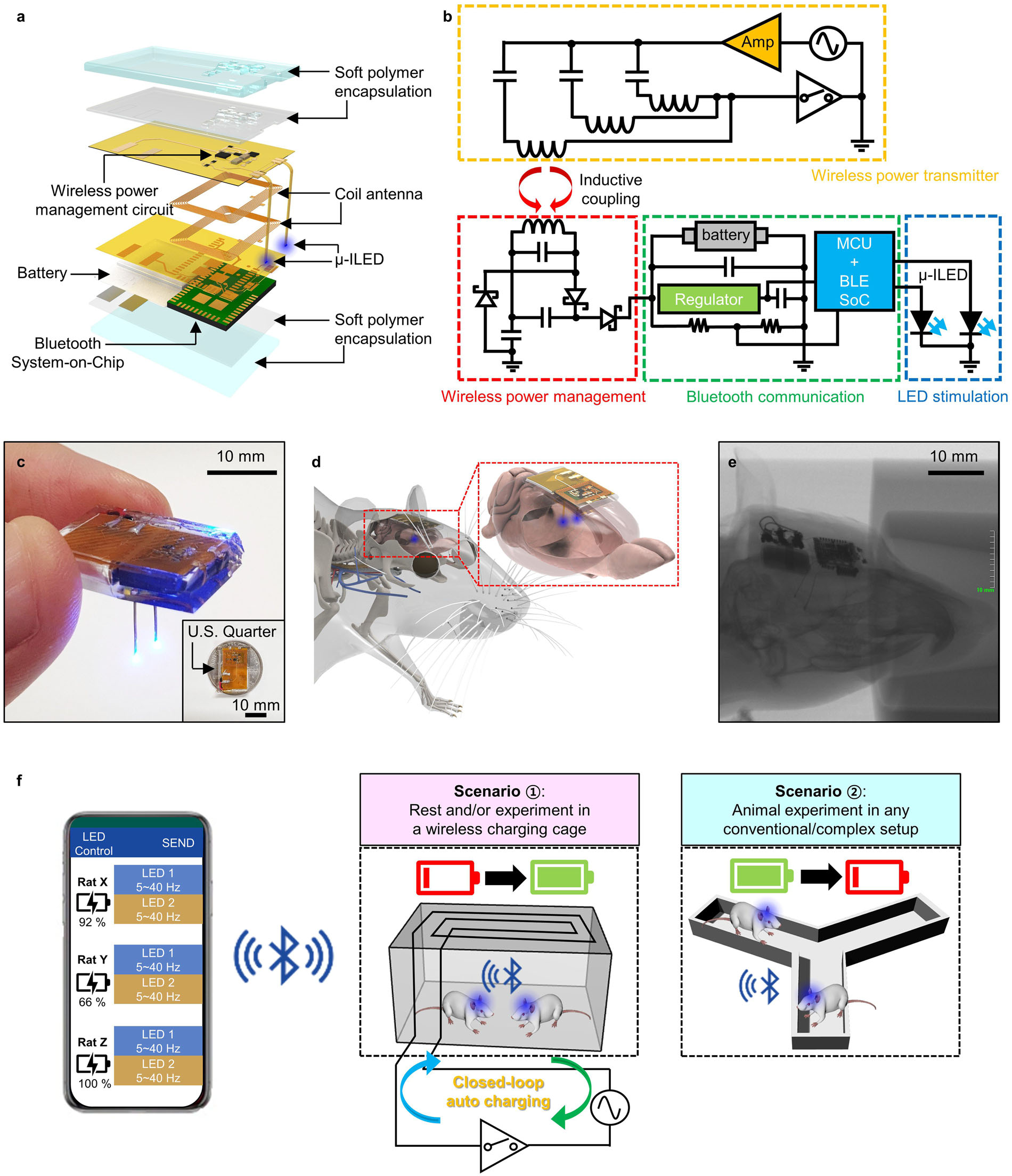
Design and operational principles. Figure 1a shows an exploded view schematic diagram of a wirelessly rechargeable, smartphone- controlled optoelectronic system (see the Methods section and Supplementary Fig. 1 for fabrication details). The wireless optoelectronic system consists of four main functional parts: (i) optoelectronic neural probes for photostimulation, (ii) a power management circuit with a flexible coil antenna and a recharge- able Lithium Polymer (LiPo) battery (GMB-300910, PowerStream Technology) for wireless charging and operation, (iii) Bluetooth Low Energy System-on-Chip (BLE SoC; RFD77101, RF Digital Corporation) for wireless control, and (iv) soft polymer encap- sulation for biocompatible device packaging. The power man- agement circuit with a coil antenna primarily helps harvest wireless RF energy to form DC electrical charging currents for the LiPo battery (12 mAh, 0.3 g). The coil antenna (16 turns dis- tributed on two interconnected layers) is constructed by pat- terning copper traces (35 μm thick) on thin polyimide (PI; 25 μm thick) layers. The bilateral neural probes integrate microscale inorganic light-emitting diodes (μ-ILEDs; blue (470 nm), 270 × 220 × 50 μm3; Supplementary Fig. 2), which are controlled by the BLE SoC to enable wireless optogenetic modulation in both left and right sides of the brain. Each probe is 100 μm-thick and 300 μm-wide, making its cross-sectional area similar to that of single-mode optical fibers (0.03 mm2 for an optoelectronic probe vs. 0.042 mm2 for an optical fiber). Previous studies demonstrated biocompatibility and long-term in vivo stability of this type of optoelectronic probes in brain tissue17,19,20,23,24. Soft polymer encapsulation has a key role in not only providing device pro- tection from bio-fluids and external shock, but also allowing conformal bio-integration for adaptive and reliable operation inside the body. The encapsulation consists of multiple polymer layers. The inner encapsulation layers are composed of poly- dimethylsiloxane (PDMS; 600 μm thick) and Parylene C (7 μm thick, 0.083 g mm m–2 day–1 water vapor permeability) and work as a protection barrier against biofluid, while the outer ultrasoft polymer (33.4 kPa, 1400 μm thick; Ecoflex GEL, Smooth-On Inc.) offers a biocompatible mechanical buffer for seamless chronic integration with tissue (Supplementary Fig. 3). All the materials and electronic components are commercially available and can be processed and assembled using standard fabrication techniques, thus facilitating mass production and deployment of devices for neuroscience research.
The circuit diagram of the overall wireless system is illustrated in Fig. 1b. Both a wireless power transmitter (Fig. 1b, top) and a wireless receiver (i.e., wireless optoelectronic device; Fig. 1b, bottom) are designed to match the resonant frequency at 6.78 MHz, following the Alliance for Wireless Power (A4WP) standard, which is broadly used for simultaneous wireless charging of multiple devices. As the coil antenna of the device receives the wirelessly transmitted power via inductive coupling, it supplies a rectified and multiplied voltage to the battery for energy harvesting through a voltage-doubler circuit. To prevent undesired discharging of the battery by reverse-flow of the current, the battery located at the load is connected with a Schottky diode in series. The wirelessly charged battery then delivers stable DC power to BLE SoC and μ-ILEDs for their reliable wireless operation.
Figure 1c–f highlights various features and operational concepts
Article
NATURE COMMUNICATIONS | https://doi.org/10.1038/s41467-020-20803-y
2
NATURE COMMUNICATIONS | (2021) 12:535 | https://doi.org/10.1038/s41467-020-20803-y | www.nature.com/naturecommunications Fig. 1 Design and working principles of fully implantable, wireless rechargeable, soft optoelectronic systems for in vivo optogenetics. a Exploded view schematic diagram of a soft wireless optoelectronic system with bilateral probes, consisting of microscale inorganic light-emitting diodes (μ-ILEDs), a power management circuit, radiofrequency (RF) coil antennas, a battery, and a Bluetooth Low Energy System-on-Chip (BLE SoC). b Electrical circuit diagram of the overall power regulation system, which consists of a wireless power transmitter and a wireless rechargeable optoelectronic system (i.e., wireless receiver). c Optical image of a wireless optoelectronic system held with fingers. The inset shows that the device is smaller than a US quarter.
d Conceptual illustration of a wireless optoelectronic probe system subcutaneously implanted in a rodent head for control of neural circuits deep in the brain. The inset highlights conformal integration of the device with a rat brain. e X-ray image of a rat implanted with a wireless optoelectronic system. f Operation principles of wireless optoelectronic systems in two different scenarios. The wireless implants can operate in (i) a cage equipped with a closed- loop RF auto-charging system for chronic in vivo study, or (ii) any conventional experimental setup without needing a special RF power transmitter, using the integrated battery. In all cases, a custom-designed smartphone app allows user-friendly control of the wireless implants.
NATURE COMMUNICATIONS | https://doi.org/10.1038/s41467-020-20803-y
Article
NATURE COMMUNICATIONS | (2021) 12:535 | https://doi.org/10.1038/s41467-020-20803-y | www.nature.com/naturecommunications
3
systems. The compact and lightweight electronic design (Fig. 1c; 1.4 g; 19 mm-long × 12 mm-wide × 5 mm thick) allows seamless integration of the device inside the body of small animals such as rodents and allows their undisturbed naturalistic behavior and movement (Fig. 1d and e and Supplementary Fig. 4). The former feature of the device, when compared with contemporary head- mounted systems15–21, substantially reduces the risk of device damage and unwanted stress on the tissue where the device is implanted, which may be caused by heavy interactions between animals especially in group housing conditions and/or by chance of bumping the device on rigid cages during free movement. In addition, the approach of integrating wireless power transfer with a rechargeable battery provides unique attributes that make it surpass existing battery-powered and battery-free wireless tech- nologies. One of the most important features of this design is that wireless recharging capability completely removes the need for intermittent replacement of batteries, opening opportunities for non-disruptive chronic in-body operation. Furthermore, powered by an integrated battery, the device enables operations indepen- dent of environment and power setup, making their use more versatile. Some possible scenarios of its use in behavioral neuroscience research are illustrated in Fig. 1f. The devices can be wirelessly charged while animals move freely in a home cage equipped with a wireless closed-loop auto-charging system. Once devices are fully charged, animals can be placed in “any” experimental setup (i.e., no need for a power transfer setup), thereby facilitating their wide deployment for numerous neu- roscience studies. In all cases, using a custom-designed smart- phone app, μ-ILED operation (5−40 Hz with 10 ms pulse width) can be controlled wirelessly, and the battery level can be monitored in real-time through BLE communication (Fig. 1f, Supplementary Fig. 5, and Supplementary Movie 1). BLE is an attractive wireless control scheme for neuroscience research, which overcomes limitations of both IR15,17,18 and other RF wireless controls20–27. Some of the advantages of BLE control include highly selective control of single or multiple animals within the vicinity, no line-of-sight handicap, long working distance (up to ~100 m), and bidirectional communication that enables closed-loop control, as demonstrated in our simulation experiment (Supplementary Fig. 6). All the aforementioned characteristics make this tool highly versatile and potent option for chronic in vivo applications in neuroscience research.
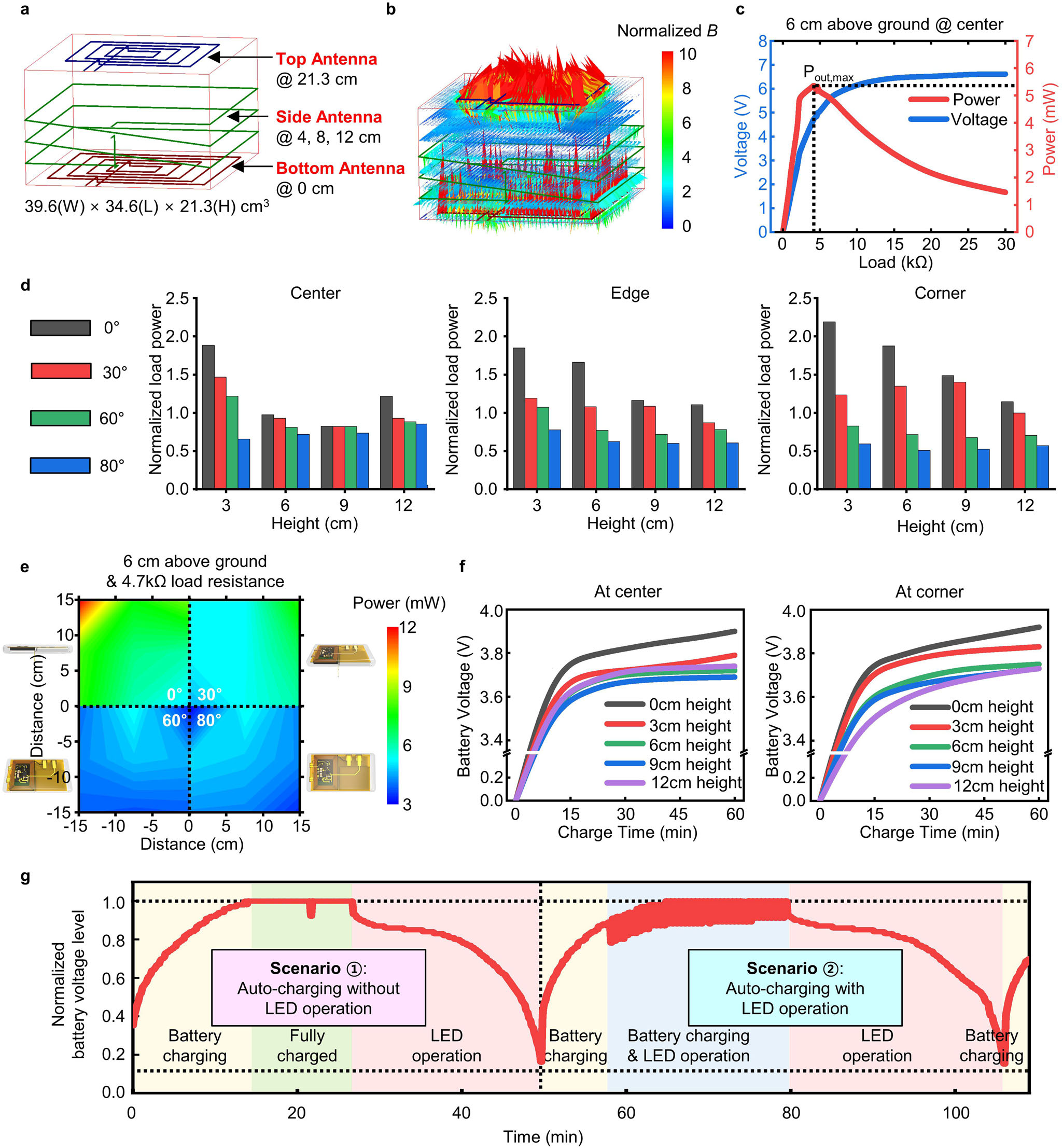
Electrical characteristics of wireless battery charging systems. The soft optoelectronic implants can be recharged wirelessly via inductive coupling at 6.78 MHz, while animals stay in their native home cages. Figure 2 shows the electrical characteristics of the wireless battery charging systems under various operational conditions in a typical rat cage (39.6 × 34.6 × 21.3 cm3) installed with three RF coil antennas located at the top (blue, 21.3 cm height), side (green, heights of 4, 8, and 12 cm), and bottom (red, 0 cm height) (Fig. 2a). The antennas are designed to be integrated with a rat cage through a simple assembly process (Supplemen- tary Fig. 7) to allow facile and rapid setup for different cages with the same dimensions. In the RF transmitter design, the side antenna alone or the top and bottom antennas without the side antenna are not sufficient for effective wireless charging of the devices implanted in freely moving rodents due to either rela- tively weak magnetic field generation (Supplementary Fig. 8a) or field vacancy in 3D space (Supplementary Fig. 8b), respectively.
By operating all three antennas simultaneously, the wireless charging system can supply magnetic fields strong enough to cover all over the 3D space within the cage (Fig. 2b, Supple- mentary Fig. 8c, and Supplementary Movie 2), thereby supporting omni-locational energy harvesting.
Wireless optoelectronic devices (i.e., receivers) are designed to effectively scavenge transmitted RF power regardless of their locations and angles within the cage. Figure 2c shows the rectified voltage and the delivered power to the load of a wireless device with different load resistances at the cage center (6 cm height) when 12.5 W input power is supplied to the transmit loop antennas of the cage. The peak delivered power (~5.3 mW) can be obtained at a voltage of ~5 V, which is achieved by rectification and multiplication through the wireless power management circuit (Fig. 1b, red dotted box). Overall, these devices show some degree of variation in wirelessly received power depending on their locations (center, edge, and corner), heights (3 cm, 6 cm, 9 cm, and 12 cm above the ground), and angular orientations (0°, 30°, 60°, and 80° with respect to horizontal plane) inside the cage, demonstrating a clear inverse relationship between the angular orientation and the received power across the 3D space (Fig. 2d, e). However, there is no dramatic decrease in energy- harvesting efficiency even at very high angular orientation (80°) or with height changes towards the middle space of the cage, thereby allowing stable wireless charging of the battery. This is owing to the combinatorial antenna design setup that combines fields from the top, the side, and the bottom coils to offer effective field coverage in space and direction within the cage.
A proof-of-concept experiment verifies the device capabilities for wireless charging. To simulate in vivo operation, we immersed the device in saline water (0.9%) and characterized the battery charging behavior at various locations inside the cage (Fig. 2f and Supplementary Fig. 7b). For all cases, 45 min was enough to charge the battery (~3.7 V) to operate a μ-ILED at 5 −40 Hz with a 10 ms pulse width for >40 min (Supplementary Fig. 9a, b). This means that charged devices can be operated anywhere and anytime without relying on the power transfer setup anymore, thus overcoming the critical limitation of current implantable, battery-free wireless device technologies22–27. Note that the device operation time can be further increased by employing a battery with a larger capacity and/or a more advanced low power BLE SoC (Supplementary Fig. 9c, e).
The optoelectronic devices can also be automatically charged wirelessly through a closed-loop system integrated with the RF power transmitter (Fig. 1b, yellow dotted box). The wireless auto- charging system (Fig. 1f, middle) continuously monitors the battery level of the devices through Bluetooth communication and turns on the RF transmitter for wireless power transfer if the battery level goes below 15% (Supplementary Fig. 10). This closed-loop charging scheme prevents the battery from being fully discharged, thereby making the devices always on standby for wireless triggering. Figure 2g and Supplementary Movie 3 show a
Demonstration Of The Automatic Wireless
charging of the devices. Real-time measurement of the battery voltage level of the devices during operation within a wireless charging cage verifies the capability of the wireless closed-loop system, which will not necessitate physical interference with freely moving animals during behavioral experiments.
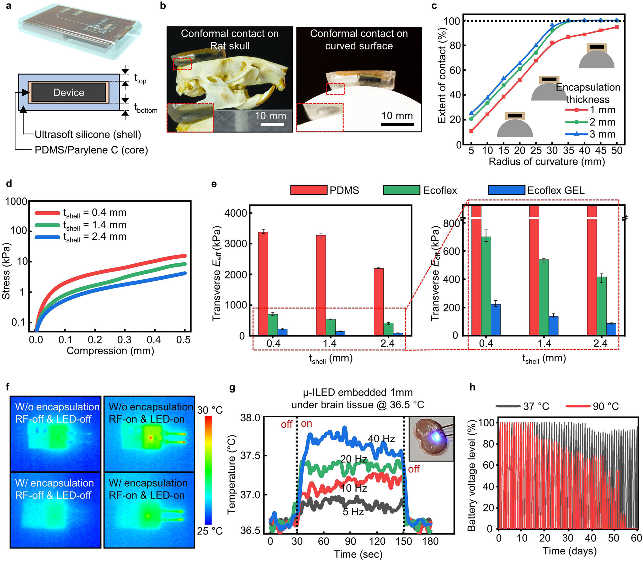
Mechanical and thermal characteristics of soft wireless optoe- lectronic systems. Wirelessly rechargeable optoelectronic systems are packaged into a soft, tissue-compatible device platform that can adapt to deformation and conform to curvilinear surfaces inside the body. The soft packaging platform consists of a thin bilayer (core) of PDMS (0.6 mm) and Parylene C (7 μm), which acts as a waterproof barrier against biofluid penetration, and an outer ultrasoft silicone gel (shell; Ecoflex GEL, Smooth-On Inc.; 33.4 kPa; 1.4 mm), which works as a mechanical buffer (Fig. 3a).
This core/shell soft polymer composite system provides several key features for fully implantable systems; it offers (i) perfect
Article
NATURE COMMUNICATIONS | https://doi.org/10.1038/s41467-020-20803-y
4
NATURE COMMUNICATIONS | (2021) 12:535 | https://doi.org/10.1038/s41467-020-20803-y | www.nature.com/naturecommunications Fig. 2 Electrical characteristics of wireless rechargeable optoelectronic systems. a, b Schematic diagram (a) and simulated magnetic field density (B) (b) of a rat cage (39.6 cm (W) × 34.6 cm (L) × 21.3 cm (H)) with three loop antennas (top, side, and bottom antenna). c Measurement of rectified voltage (blue line) and power delivered to the load (red line) of a wireless device with different load resistances (from 7–30 kΩ), which was placed at the center with a 6 cm height above the ground of the rat cage. The maximum output power (~5.3 mW) was obtained with a 4.7 kΩ load resistance, when an input power of 12.5 W was transmitted. d Normalized power at the output load (4.7 kΩ) of wireless devices at various locations (center, edge, and corner), heights (3, 6, 9, and 12 cm) and orientations (0°, 30°, 60°, and 80°) inside a rat cage. e Variation of energy-harvesting efficiency with respect to location and angular orientation of a device at a height of 6 cm in the rat cage. f Wireless battery charging characteristics in saline water (0.9%) at various heights (0, 3, 6, 9, and 12 cm) for the device located at the center (left) and the corner (right) of the cage. Battery charging was started after the battery was fully discharged. g Real-time monitoring of the battery level during the wireless closed-loop auto-charging operation of the optoelectronic system in two different sequential scenarios: wireless auto-charging (i) without and (іі) with LED operation. When the battery voltage level reaches the preset maximum, charging is automatically turned off temporarily for 10 s to confirm whether the battery is actually fully charged (see small dimple in the recorded signal at 22 min). The small fluctuation of the battery voltage level appearing between 58 and 80 min is due to electrical noise caused by the LED operation. The proof-of-principle operation was carried out with a device immersed in saline water (0.9%), which was located at the center of the rat cage floor.
NATURE COMMUNICATIONS | https://doi.org/10.1038/s41467-020-20803-y
Article
NATURE COMMUNICATIONS | (2021) 12:535 | https://doi.org/10.1038/s41467-020-20803-y | www.nature.com/naturecommunications
5
conformal integration with curved body surfaces, (ii) thermo- mechanical compatibility between the implant and soft brain tissue, (iii) protection of the electronic system from biofluid, and (iv) light device weight that cannot be achieved using conven- tional encapsulation materials such as metals and glass. Figure 3b shows optical images of polymer-encapsulated devices (5 mm in total thickness) conformally interfaced with curved surfaces of a rat skull (left) and a hemispherical structure (right; the radius of curvature of 35 mm). Further, as shown in Fig. 3c and Supple- mentary Fig. 11, the extent of contact on the curved surface is enhanced with an increasing thickness of the outer ultrasoft silicone layer, saturating to peak values with a total encapsulation thickness of 2 mm (1.4 mm thick Ecoflex GEL shell and 0.6 mm- thick PDMS core). With this encapsulation, the devices can make perfect conformal integration with any surface with a radius of curvature of 35 mm or greater without bending the device Fig. 3 Mechanical and thermal characteristics of soft wireless rechargeable optoelectronic implants. a Schematic diagram of an implant encapsulated with soft biocompatible polymers (top) and its cross-sectional view (bottom). b Optical images of the implant conformally mounted on a rat skull (left) and a half-cylinder structure with a radius of curvature of 35 mm (right). The insets show the zoomed-in images of the device edge, highlighting perfect conformal integration with the curved surfaces. c Extent of conformal contact on half-cylinder structures with various radii of curvature (5–50 mm) for the devices with silicone gel encapsulation with different thicknesses (tshell = 0.4, 1.4, and 2.4 mm). d Mechanical stress as a function of compression for devices coated with silicone gel with different thicknesses (tshell = 0.4, 1.4, and 2.4 mm). e Transverse effective Young’s modulus (Eeff) of devices coated with three common elastomers (PDMS, Ecoflex, and Ecoflex GEL) as a function of the encapsulation thickness (left) (n = 3). The zoomed-in graph (right) highlights the significantly low effective Young’s modulus of a device with Ecoflex GEL encapsulation, compared with devices coated with PDMS or Ecoflex.
Error bars indicate maximum and minimum values. f Infrared images showing surface temperature of devices without (top) and with (bottom) polymer encapsulation before (left) and during (right) wireless charging and μ-ILED operation (40 Hz, 10 ms pulse width). The measurement was made in an ambient environment at room temperature. g Temperature of explanted brain tissue with a μ-ILED operated at different pulse frequencies (5, 10, 20, and 40 Hz; 10 ms pulse width) at 1 mm beneath the tissue surface (inset). To mimic a biological environment, the baseline temperature of the explanted brain tissue was maintained at 36.5 °C using a heater. h Battery voltage level as a function of time during repeated device operation—that is, repetition of wireless charging (60 min) and μ-ILED operating (20 Hz, 10 ms pulse width)—after immersing the devices in saline water with temperatures of 37 °C and 90 °C.
Article
NATURE COMMUNICATIONS | https://doi.org/10.1038/s41467-020-20803-y
6
NATURE COMMUNICATIONS | (2021) 12:535 | https://doi.org/10.1038/s41467-020-20803-y | www.nature.com/naturecommunications
Related Journal Articles & DOI Links
Selected peer-reviewed publications relevant to 12 Lead ECG Acquisition. Click the DOI to access the full paper (may require institutional access).
-
1. Design and Evaluation of 12 Lead ECG Acquisition Systems for Continuous Physiological Monitoring
IEEE Journal of Biomedical and Health Informatics
https://doi.org/10.1109/JBHI.2020.2981234 -
2. Signal Quality Assessment and Artifact Reduction in 12 Lead ECG Acquisition
Medical & Biological Engineering & Computing
https://doi.org/10.1007/s11517-020-02145-6 -
3. Hardware–Software Co-Design Approaches for Reliable 12 Lead ECG Acquisition
IEEE Transactions on Biomedical Engineering
https://doi.org/10.1109/TBME.2019.2895762 -
4. Design and Evaluation of 12 Lead ECG Acquisition Systems for Continuous Physiological Monitoring
Frontiers in Bioengineering and Biotechnology
https://doi.org/10.3389/fbioe.2020.00123 -
5. Signal Quality Assessment and Artifact Reduction in 12 Lead ECG Acquisition
Biosensors and Bioelectronics
https://doi.org/10.1016/j.bios.2021.112345 -
6. Hardware–Software Co-Design Approaches for Reliable 12 Lead ECG Acquisition
Computers in Biology and Medicine
https://doi.org/10.1016/j.compbiomed.2021.104567 -
7. Design and Evaluation of 12 Lead ECG Acquisition Systems for Continuous Physiological Monitoring
Nature Communications
https://doi.org/10.1038/s41467-020-12345-6
Why Choose Us?
Bangalore guidance for robotics, Spectre and autonomous systems projects.
Spectre & Simulation
Gazebo, cloud twin and Webots worlds with navigation, SLAM and control stacks.
Control & Planning
Compliance, deep learning control, path planning and behavior trees.
Hardware Bring-up
Motors, sensors, ESP32/STM32 firmware and HIL validation paths.
Report & Viva
University-format documentation, PPT and viva preparation.
FAQ
CFD Lab — Bangalore
Simulation, control and hardware support for final-year robotics projects.
Stacks
Worlds
Digital Twin
Control
Robots
Offline
Bring-up