3D Printed Biomimetic Cochleae And Machine
learning co-modelling provides clinical informatics
1,2,9✉
Cochlear implants restore hearing in patients with severe to profound deafness by delivering electrical stimuli inside the cochlea. Understanding stimulus current spread, and how it correlates to patient-dependent factors, is hampered by the poor accessibility of the inner ear and by the lack of clinically-relevant in vitro, in vivo or in silico models. Here, we present 3D printing-neural network co-modelling for interpreting electric field imaging profiles of cochlear implant patients. With tuneable electro-anatomy, the 3D printed cochleae can replicate clinical scenarios of electric field imaging profiles at the off-stimuli positions. The co- modelling framework demonstrated autonomous and robust predictions of patient profiles or cochlear geometry, unfolded the electro-anatomical factors causing current spread, assisted on-demand printing for implant testing, and inferred patients’ in vivo cochlear tissue resis- tivity (estimated mean = 6.6 kΩcm). We anticipate our framework will facilitate physical modelling and digital twin innovations for neuromodulation implants.
Open
NATURE COMMUNICATIONS | (2021) 12:6260 | https://doi.org/10.1038/s41467-021-26491-6 | www.nature.com/naturecommunications
T
he use of neuromodulation implants and bioelectronic devices has been increasing rapidly and is anticipated to form a new era of medicine1,2. By delivering local electrical stimuli to tissues, these electronic implants restore lost neural functions in tissues or nerves or modulate signalling patterns for therapeutic outcomes2,3. Cochlear implants (CIs) are by far the most widely used neuromodulation electronic implants, with well over 500,000 CIs having been implanted worldwide4, and their prevalence is only expected to grow more rapidly with the pro- jected increase in the elderly population1,4. Bypassing the mal- functioning peripheral auditory mechanisms by direct neural stimulation, the CI electrode array is designed to restore sound perception. It also attempts, in broad terms, to reproduce the tonotopic architecture of the cochlea by delivering frequency- specific programmed stimulation at localised regions of the cochlear lumen; this, in turn, stimulates separate auditory neural elements5,6 (Fig. 1a), with lower sound frequencies represented apically and higher frequencies basally.
A major limitation of today’s neural prostheses is their imprecise control of the administered stimulus, arising from the intrinsic conductive nature of biological tissues7,8 and particularly of the biological fluids in the inner ear5,9. This limitation is well exemplified by the ‘current spread’ problem of CIs, where the uncontrolled spread of electrical stimulus leads to off-target excitation of the neighbouring auditory nerve fibres (thus causing a mismatch or ‘smeared’ representation in the perceived sound
Intended)9
(Fig. 1a).
Tissue
conductivity and implant positioning are suggested to be the primary patient-specific factors controlling the intracochlear voltage distribution induced by CIs9–12. In particular, cochlear anatomy (in terms of size and shape) is variable13, with different levels of volumetric conductance of cochlear fluids affecting the intracochlear voltage induced by stimulation. Moreover, patho- physiological conditions could affect the electrical conductivity of the cochlear bony walls, and thus CI induced electric fields14. As the cochlea is embedded deep inside the temporal bone and has a complex anatomy, its electrical characteristics are difficult to quantify in a living subject. As a result, a model that deciphers how different characteristics of a patient’s cochlea affect the sti- mulus spread would be a valuable tool for predicting and opti- mising the stimulus signals and provide insights into factors controlling the large variation in patient-specific CI performance and sound perception.

Although various physical and computational models have been developed for CI testing9,12,15–17, they are insufficient to evaluate the stimulus spread in human cochleae. Animal models are well-established for in vivo CI testing, but due to the drastic differences between the cochlear anatomies of humans and
Are
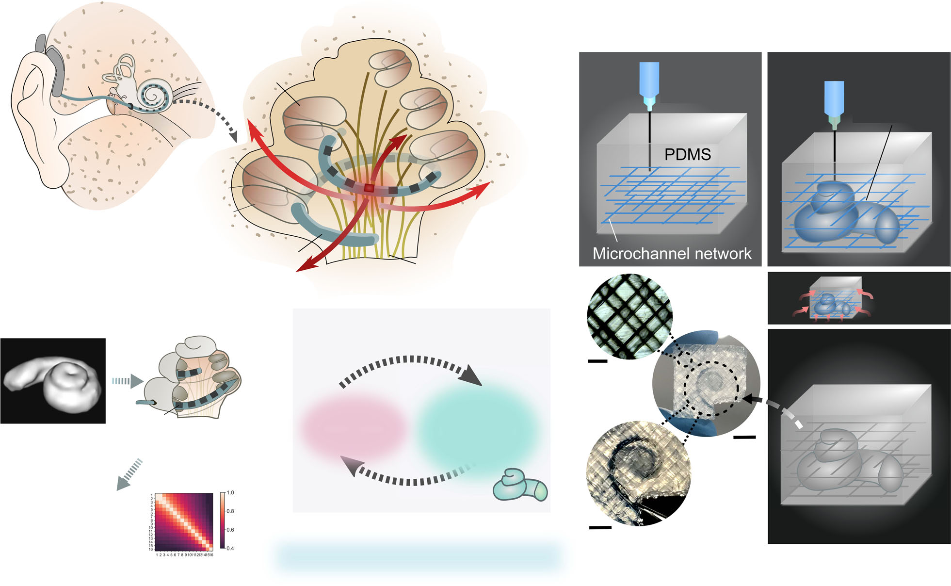
obtained1,3. Though human cadavers can provide anatomical fidelity, they are limited in supply and have altered electrical properties due to preservation and post-mortem changes19. In silico approaches, such as finite element modelling (FEM), can overcome ethical, sample availability and cost issues20. However, Fig. 1 3PNN co-modelling approach with embedded 3D printing of biomimetic cochleae for reproducing the CI stimulus spread characteristics. a Schematic of the auditory system and the cochlea with a CI implanted. The ‘current spread’ problem induced by a stimulating electrode of the CI electrode array is indicated. b Schematic of the routine CI assessment process; 1. Preoperative CT scan of a patient’s cochlea, which typically only has sufficient resolution to reveal the ensemble spiral-shaped cavity of a cochlea; 2. Implantation of the electrode array of a CI in the scala tympani of the cochlea; 3.

Acquisition of an intra-operative EFI (electric field imaging) profile from a patient, which is derived from recording the induced intracochlear voltage V measured at each electrode upon injecting consecutive current pulses at each electrode in the array. The voltage measurements are then converted to transimpedance magnitude |z| by normalising the voltage V with the stimulation current impulse Istim (|z| = V/Istim). The off-stimulation (off-diagonal) measurements in the EFI present information about the tissue impedance9. c Overview of the 3PNN co-modelling framework for providing clinical informatics. d Schematic of the embedded 3D printing strategy to produce the electro-mimetic bone matrices and the biomimetic cochleae.

Article
NATURE COMMUNICATIONS | https://doi.org/10.1038/s41467-021-26491-6
2
NATURE COMMUNICATIONS | (2021) 12:6260 | https://doi.org/10.1038/s41467-021-26491-6 | www.nature.com/naturecommunications existing FEM modelling is limited by several factors, including scant knowledge of the electrical properties of live human cochlear tissues to fit different in vivo cases21, the inability to capture patient-dependent anatomically-guided CI positioning and the underdetermined boundary conditions and physical/ empirical law descriptions15 (discussed in Supplementary Fig. 1a).

Here, we establish a library of 3D printed cochlear models (n = 82) for robust modelling of clinical CI testing data. These 3D printed cochleae capture the diverse geometries that human cochlear lumens can take, along with a spectrum of bone tissue resistivities, using ranges reported in in vivo human studies.

Supplementary Video 1 shows CT scans of exemplar 3D printed biomimetic cochleae. Using these models, a broad spectrum of clinically representative electric field imaging (EFI) profiles (normalised intracochlear voltage distribution along the CI elec- trode array) is acquired. Then, by inputting EFI profiles acquired from the biomimetic cochleae as the training dataset, we establish a neural network machine learning model termed 3PNN (3D printing and neural network co-modelling, overview shown in Fig. 1c), which provides powerful clinical informatics such as deciphering patient-specific attributes of CI current spread and inferring patient-dependent cochlear tissue resistivity.

Results
Designable electro-mimetic bone matrices. The human cochlea is a spiral-shaped hollow organ embedded in the temporal bone (Fig. 1a). Since there were no established reports of in vivo cochlear tissue conductivities, our first goal was to establish a printable material system that could emulate the range of reported bone tissue conductivities (hereafter, termed electro- mimetic bone matrix). In vivo human studies estimated that the electrical resistivities of human skulls vary widely between 0.6 to
And
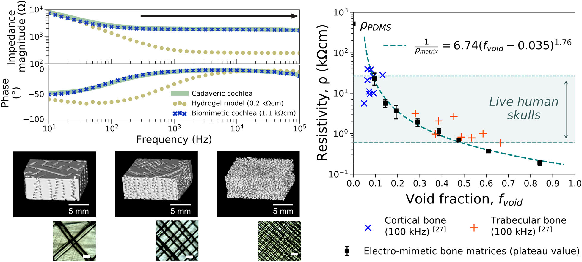
porosity22–26 (Supplementary Fig. 2). To reproduce the mesoscale electrical properties of bone, we take inspiration from the micro-architecture of bones, which consists of conductive fluid-filled interconnected pores sur- rounded by a poorly conductive mineralised phase27. Thus, we structured an electro-mimetic bone matrix that exhibits inter- connected saline-filled channels inside a crosslinked PDMS (polydimethylsiloxane) elastomer. The interconnected channels were created by embedded printing a Pluronic F127 sacrificial ink in pre-crosslinked PDMS (Fig. 1d and Supplementary Video 2), permitting flexible and precise tuning of the void density and, therefore, the resistivity of the electro-mimetic bone matrices (Supplementary Fig. 3e). Comparing our printing method with stereolithography, Pluronic F127 can be easily removed after printing28 and further enhances the wettability of PDMS due to its amphiphilic nature. The channels were then filled with physiological saline, which we hypothesise is important to emulate the electrical impedance properties of bone tissues, as pores in bone are normally wet with extracellular fluids. The electrochemical impedance spectroscopy (EIS) measurements in Fig. 2a and Supplementary Fig. 4 show that an electro-mimetic bone matrix can be designed to exhibit impedance properties matching those of a cadaveric cochlear bone in a human head for the entire frequency range (f = 10 Hz–100 kHz) studied in EIS. In particular, the Fourier fundamental frequency associated with the EFI stimulation pulse, (estimated to be f ~14 to ~20 kHz depending on CI type), lies in the frequency-independent impedance magnitude plateau region. By varying the void fraction in the electro-mimetic bone matrix from 20 to 84%, the resistivity of the matrix that is derived from the impedance magnitude plateau can be tuned from 0.2 to 23.4 kΩcm (Fig. 2b), covering almost the entire reported resistivity range of live human skull tissues22–26 (0.6–26.6 kΩcm, Fig. 2c).

Figure 3 shows a material property chart summarising the electrical resistivity and Young’s modulus for a range of biological tissues and polymeric materials. The 3D printed electro-mimetic
Impedance Magnitude Plateau (> ~300 Hz)
Fig. 2 Electrical properties of electro-mimetic bone matrices. a Bode plot showing the impedance properties of a cadaveric cochlea in a human head, and 3D printed cochlear models made of an electro-mimetic bone matrix and a hydrogel. The frequency range associated with the impedance magnitude plateau is indicated. b µ-CT reconstructed images (top) and optical microscopic images (bottom) of the electro-mimetic bone matrices at different volumetric void fractions (fvoid). Scale bar of the optical microscopic images = 500 µm. The resistivities of the matrices were determined from their plateau impedance magnitude and the size of the samples. n = 3 independent samples. c Resistivity of the electro-mimetic bone matrices (plateau value, n = 3 independent samples) as a function of fvoid, compared to the reported resistivities of bovine cortical and trabecular bones27. The relationship between the resistivity of the electro-mimetic bone matrix and fvoid is well-described by a percolation equation of a conductor-insulator composite54 (Supplementary Fig. 3e). Data were presented as mean values ± SD.

NATURE COMMUNICATIONS | https://doi.org/10.1038/s41467-021-26491-6
Article
NATURE COMMUNICATIONS | (2021) 12:6260 | https://doi.org/10.1038/s41467-021-26491-6 | www.nature.com/naturecommunications
3
bone matrices cover a wide resistivity range, which cannot be imitated by a single printable material (i.e. thermoplastics or hydrogels) alone or a hydrogel-fillers matrix (i.e. bioceramics and PDMS microbeads dispersed in hydrogels) (Supplementary Fig. 5a). Apart from electrical resistivity, we suggest that Young’s modulus of the model is also an important consideration for electronic implant testing. Adopting PDMS as the solid phase of the electro-mimetic bone matrix not only facilitates the ease of embedded printing, but also imparts favourable mechanical properties as a CI testing platform. With Young’s modulus in the 106 Pa range, we estimate that the force associated with CI electrode insertion will not induce a significant deformation to the matrix (Supplementary Note 1). At the same time, the compliance of the matrix mitigates mechanical damage to the fine electrodes of a CI, which is commonly experienced when inserting CI electrode arrays repeatedly in cadaveric samples (modulus of hard tissues >109 Pa). Hence, multiple insertions can take place for the same CI electrode array, which is of practical importance due to the time-consuming fabrication and costs associated with a fully functioning CI. Overall, the above results suggest the electro-mimetic bone matrices be a suitable material system for creating electroanatomical models of human cochleae.

3D printed biomimetic cochleae. Clinically, a CI electrode array is inserted into the scala tympani, one of the three cochlear ducts14 (Fig. 1a). As a coarse-grained approach to replicate the electroanatomical features of a CI implanted cochlea, we approximate the cochlea as one ensemble spiral cavity with continuously narrowing diameter and omit the inner soft-tissue membranous structures inside the cochlea, such as the basilar typical patient’s preoperative CT scan as routine clinical assess- ment (Fig. 1b), the scan resolution only permits the identification of the shape of the ensemble cochlear lumen and not the fine microanatomical soft-tissue structures (Supplementary Fig. 6); and secondly, our preliminary finite element modelling shows membrane inside a cochlea on the off-stimulation EFI profile is likely to be insignificant, as the boundary impedances are dominated by surrounding bone tissues (see Supplementary Fig. 1b). Therefore, we constructed the biomimetic cochleae by embedded 3D printing a tapered and spiral-shaped cochlear lumen cavity inside an electro-mimetic bone matrix (Fig. 1d and Supplementary Video 2). The spiral-shaped cavity was filled with physiological saline to mimic the ionic conduction milieu in the cochlea (perilymph) (Supplementary Fig. 3c) and the conduction properties at the electrode-electrolyte interface.

Since the size and the shape of a cochlea is unique to each individual and can vary greatly from person-to-person13,29,30, we assign four geometrical descriptors to parametrically describe the reported anatomical variations in CI implanted human cochleae; they are basal lumen diameter, taper ratio, cochlear width and cochlear height (see definitions in Fig. 4a and Supplementary Table 1). For electroanatomical modelling of cochleae, we incorporated a fifth descriptor, the matrix resistivity, which is controlled by the void fraction of the electro-mimetic bone matrix. In total, 82 biomimetic cochleae were printed at different combinations of model descriptors. With this physical model library, we artificially reconstructed a broad spectrum of the electroanatomical features of human cochleae with even feature distributions.

Figure 4b shows high-resolution µ-CT scans of a cadaveric cochlea and an exemplar 3D printed biomimetic cochlea with a CI inserted. It is worth noting that the CI electrode-to-spiral centre distance displayed in the 3D printed cochleae matches
Measured
clinically from patients’ CT scans31 (Fig. 4c(i)). Despite only four geometric descriptors being used to describe patient cochlear geometry, biomimetic cochleae with similar patients’ geometric descriptors can approximately capture the overall contour of the cochlear lumen which encapsulates the length of the CI array (up to 1.5 turns, n = 3, see corresponding analysis in Supplementary Fig. 7a). Hence, similar plain X-ray imaged electrode positions and the angular insertion depths were observed in the biomimetic cochleae and in the patients implanted with the same type of CI (Fig.

Supplementary
Fig. 7b).
The
dependence of the CI angular insertion depth on the cochlear width was also similar, comparing the biomimetic cochlea data and the patient data (Supplementary Fig. 7c). This gives further confirmation that the 3D printed cochleae have adequate structural rigidity and anatomy to provide geometrically-guided implant insertion and positioning. It should be noted that since the 3D printed cochleae do not present the intracochlear membrane structures, the associated volume restriction effects on CI electrode positioning might not be fully captured in the 3D printed models.

(Normalised
intracochlear voltage distribution) in our cochlear models with a CI1J (Advanced Bionics HiRes 90 K® implant with HiFocusTM 1 J electrode) electrode array inserted. EFI samples the intracochlear voltage (V) along with the electrode array in response to a current injection or a stimulation impulse (Istim) at each electrode (Fig. 1b).

The off-stimulation measurements in EFI profiles contain informa- tion about the induced voltage spread characteristics of the cochlea. EFIs and similar measures (e.g. transimpedance matrix from
84% Void
Fig. 3 Wide resistivity tuneability and adequate mechanical properties of electro-mimetic bone matrices. A map of resistivity versus Young’s modulus of human tissues, thermoplastics, the hydrogel-fillers matrices and the electro-mimetic bone matrices (plateau values) was tested in this study (n = 3 independent samples). The compositions of the hydrogel and hydrogel-fillers matrices tested here are listed in Supplementary Fig. 5a.

Young’s modulus of the electro-mimetic bone matrix was estimated by scaling Young’s modulus of pure PDMS (1.7 MPa at a curing temperature of 60 °C55) linearly with the fvoid of the matrix. Tissues and thermoplastics data and Young’s modulus of hydrogels were compiled from literature22–27,56–60. Data of the electro-mimetic bone matrices are presented as mean values ± SD.

Article
NATURE COMMUNICATIONS | https://doi.org/10.1038/s41467-021-26491-6
4
NATURE COMMUNICATIONS | (2021) 12:6260 | https://doi.org/10.1038/s41467-021-26491-6 | www.nature.com/naturecommunications Cochlear Corporation® or Impedance Field Telemetry from MED- EL®) are commonly used as part of the routine CI clinical assessment.

To further demonstrate the importance of having a realistic bone matrix resistivity in reproducing the patient EFI profile, we also fabricated models made of materials with contrasting conduction properties, hydrogels (representing the highly con- ductive case) and solid PDMS (representing the insulating case).

Figure 4d shows the mean patient EFI profile derived from 97 patients compared with the EFI profiles of the 3D printed models with different matrix material properties. We found that the solid PDMS model led to a steeper and extremely asymmetrical EFI profile (as seen in the stimulation at the medial electrode), strongly mismatched with real patient profiles. In comparison, the conductive hydrogel model resulted in a low magnitude EFI profile, which sits outside the patient population EFI. By replicating realistic bone resistivities with electro-mimetic bone matrices, our biomimetic cochlea can be designed to match real patient stimulus spread characteristics.

Clinically validated 3PNN shows high statistical predictive performance. By training a neural network (NN) machine learning model with the dataset of EFI profiles acquired from the 3D printed biomimetic cochleae, a 3D printing and neural net- work co-modelling (3PNN) framework (Fig. 5a) was established to model the relationship between EFIs and the electroanatomical features of the CI implanted biomimetic cochleae. Reasons for using neural network modelling instead of other existing com- putational models are discussed in Supplementary Note 2. To support various application needs, we developed forward-3PNN and inverse-3PNN. Forward-3PNN is used when patients’ cochlear geometry is known (i.e. through a preoperative CT scan), and the algorithm can predict the most probable off-stimulation EFIs arising from different electroanatomical descriptors of a cochlea. The patient-specific EFI prediction covers the initial 2–18.5 mm section of a CI electrode array from different manu- facturers that may have different electrode positions and spacings.

Inverse-3PNN is used when a patient EFI is given, and the algorithm can infer the most probable distribution of the
D
Fig. 4 3D printed biomimetic cochleae replicate the broad anatomical spectrum of human cochleae, enable geometrically-guided CI positioning and give patient-relevant EFI profiles. a µ-CT reconstructed images of the spiral lumen of the biomimetic cochlea with different geometric features. Scale bar = 2 mm. Four geometric descriptors are used—basal lumen diameter, taper ratio, cochlear width and cochlear height. Detailed definitions and the range of the descriptors tested in this study can be found in Supplementary Table 1. b µ-CT reconstructed images of (i) a cadaveric cochlea and (ii) the lumen of an exemplar 3D printed biomimetic cochlea with CI electrode array (marked green) implanted. Scale bar = 2 mm. c(i) The electrode-to-spiral centre distance (n = 48) of the biomimetic cochleae, compared to the electrode-to-modiolus distance of human cochleae with the same CI electrode type implanted (HiFocusTM 1 J electrode array), replotted from literature31. c(ii) Example showing overlapped CT and x-ray images of the CI electrode positions in a patient’s cochlea and in a biomimetic cochlea that has similar geometric descriptors to the patient (n = 3, Supplementary Fig. 7b). Scale bar = 2 mm. d Comparison of the mean patient EFI profile (n = 97), and the EFI profiles obtained from 3D printed models made of hydrogel, solid PDMS and electro- mimetic bone matrix (3.6 kΩcm). The mean patient EFI was derived from 97 clinical EFIs that are not paired with CT information (with 91 independently acquired by Advanced Bionics® and six acquired by CI1J from our own repository), on the assumption that the insertion depths follow the suggested insertion depth of CI1J. EFIs induced by the stimulations of the basal electrode (electrode 15), the medial electrode (electrode 9) and the apical electrode (electrode 2) were shown.

NATURE COMMUNICATIONS | https://doi.org/10.1038/s41467-021-26491-6
Article
NATURE COMMUNICATIONS | (2021) 12:6260 | https://doi.org/10.1038/s41467-021-26491-6 | www.nature.com/naturecommunications
5
electroanatomical descriptors (i.e. the four geometric descriptors and the cochlear tissue resistivity) of the patient’s cochlea. The broad applicability of 3PNN on different electrode types (HiFo- cusTM 1 J electrode array (CI1J), HiFocusTM SlimJ electrode array (CISlimJ), Cochlear TM Nucleus® slim straight electrode CI622 and Cochlear TM Nucleus® slim straight electrode CI522) is validated in Supplementary Figs. 9–13, with its clinical predictive power demonstrated below.

We validated the clinical applicability of 3PNN using routinely acquired clinical data of different implant types. In total, 31 paired sets of patient’s CT scan and EFI profile were used for validation.

They were acquired using either a CISlimJ (n = 17), a CI622 (n = 6) or a CI522 (n = 8). Here, we assumed the inputs of the stimulating and the recording electrode positions follow the
(Supplementary
Table 2) for predicting the most likely outcomes. Starting with our forward-3PNN, we predicted the patients’ off-stimulation EFI profiles based on the four geometric descriptors measured from their CT scans, while taking the matrix resistivity input as 9.3 kΩcm (the mean reported resistivity of live human skulls22–26, see Supplementary Fig. 2a). Without any model adjustment for the different CI types, 28 out of the 31 EFI reconstructions achieve a MAPE (median absolute percentage error) <12% (Fig. 5b and Supplementary Fig. 11), despite of the limited resolution of patients’ cochlear CT scans, and the substitution of the unknown patient cochlear tissue resistivities with the reported mean human skull resistivity. For a selected patient (subject 4CI522) whose EFI profile matches the population mean EFI (n = 97), forward-3PNN was shown to achieve a MAPE = 8.6% for the EFI reconstruction (Fig. 5bi and Supplementary Fig. 12b, c). The capability of 3PNN to give patient-dependent EFI predictions is confirmed in Supplementary Table 3 which cross-compares the MAPEs calculated between the patients’ EFIs and the 3PNN predictions, and the MAPEs between the patients’ EFIs and the population mean. Next, we validated our 3PNN by inversely inferring the distribution of the four cochlear geometric descriptors that could match a patient’s off-stimulation EFI profile with a similarity >89% (Similarity (%) = 1 – MAPE (%)). Comparing the predicted distributions of the geometric descriptors with the corresponding patient’s features measured from their CT scans, the median MAPE is ≤8% (Fig. 5c and Supplementary Fig. 13). The above high statistical prediction accuracy demonstrates the capacity of 3PNN to autonomously predict clinical EFIs or patients’ cochlear features for different electrode types without further need to adjust the machine learning model that is trained by the dataset acquired from the CI1J.

Effect of cochlear electroanatomy on CI voltage spread. With the validated 3PNN model, we proceeded to investigate how the CI voltage spread characteristics could be affected by the four geometric descriptors and the matrix resistivity. Using for- ward-3PNN, we simulated EFI profiles by sweeping through different combinations of the five model descriptors (examples shown in Supplementary Fig. 14). In total, we sampled 3125 (5 × 5 × 5 × 5 × 5) combinations to represent the entire modelling space of the five model descriptors and predicted their off- stimulation EFIs. To parameterise the voltage spread character- istics for each predicted EFI profile, we fitted a power law fol- lowing Eq. (1), to each stimulus spread toward the apex and
1
...
Record
pos. Stim. pos.
(9.3 Kωcm)
Fig. 5 Clinical validation of 3PNN. a Schematic of the workflow of 3PNN. 3PNN was developed by training a neural network machine learning algorithm with the EFI profiles acquired from the 3D printed biomimetic cochleae. 3PNN maps the correlation between the five model descriptors and the most probable EFI profile as a function of CI electrode position. The hyperparameters of 3PNN were tuned using tenfold cross-validation to achieve the best predictive performance (Supplementary Fig. 9). b Validation of forward-3PNN for predicting patient off-stimulation EFIs (matrix resistivity input = 9.3 kΩcm). (i) Representative off-stimulation EFI predictions for different CI electrode types, as compared to the corresponding clinical patient data; and (ii) boxplots summarising the overall performance of forward-3PNN, with the median MAPE of each CI electrode type indicated on the figure. Full validation results can be found in Supplementary Fig. 11. c Overall performance of inverse-3PNN for inferring the patients’ cochlear geometric descriptors for different CI electrode types, with the median MAPE stated for each descriptor. Full validation results of inverse-3PNN can be found in Supplementary Fig. 13. In b(ii) and c the line in each box represents the median, with the box denoting the interquartile range and the whiskers denoting the ±1.5 of the interquartile range.

Article
NATURE COMMUNICATIONS | https://doi.org/10.1038/s41467-021-26491-6
6
NATURE COMMUNICATIONS | (2021) 12:6260 | https://doi.org/10.1038/s41467-021-26491-6 | www.nature.com/naturecommunications
Related Journal Articles & DOI Links
Selected peer-reviewed publications relevant to 12 Lead ECG Acquisition. Click the DOI to access the full paper (may require institutional access).
-
1. Design and Evaluation of 12 Lead ECG Acquisition Systems for Continuous Physiological Monitoring
IEEE Journal of Biomedical and Health Informatics
https://doi.org/10.1109/JBHI.2020.2981234 -
2. Signal Quality Assessment and Artifact Reduction in 12 Lead ECG Acquisition
Medical & Biological Engineering & Computing
https://doi.org/10.1007/s11517-020-02145-6 -
3. Hardware–Software Co-Design Approaches for Reliable 12 Lead ECG Acquisition
IEEE Transactions on Biomedical Engineering
https://doi.org/10.1109/TBME.2019.2895762 -
4. Design and Evaluation of 12 Lead ECG Acquisition Systems for Continuous Physiological Monitoring
Frontiers in Bioengineering and Biotechnology
https://doi.org/10.3389/fbioe.2020.00123 -
5. Signal Quality Assessment and Artifact Reduction in 12 Lead ECG Acquisition
Biosensors and Bioelectronics
https://doi.org/10.1016/j.bios.2021.112345 -
6. Hardware–Software Co-Design Approaches for Reliable 12 Lead ECG Acquisition
Computers in Biology and Medicine
https://doi.org/10.1016/j.compbiomed.2021.104567 -
7. Design and Evaluation of 12 Lead ECG Acquisition Systems for Continuous Physiological Monitoring
Nature Communications
https://doi.org/10.1038/s41467-020-12345-6
Why Choose Us?
Bangalore guidance for robotics, Spectre and autonomous systems projects.
Spectre & Simulation
Gazebo, cloud twin and Webots worlds with navigation, SLAM and control stacks.
Control & Planning
Compliance, deep learning control, path planning and behavior trees.
Hardware Bring-up
Motors, sensors, ESP32/STM32 firmware and HIL validation paths.
Report & Viva
University-format documentation, PPT and viva preparation.
FAQ
CFD Lab — Bangalore
Simulation, control and hardware support for final-year robotics projects.
Stacks
Worlds
Digital Twin
Control
Robots
Offline
Bring-up