Photoelastic Study
Fei Yang1,*, Chen Chen2,3,*, QianRong Zhou1, YiMing Gong1, RuiXue Li1, ChiChi Li4, Florian Klämpfl2, Sebastian Freund2,3, XingWen Wu1, Yang Sun1, Xiang Li5, Michael Schmidt2,3,
Duan Ma6 & Youcheng Yu1
Fabricating Ti alloy based dental implants with defined porous scaffold structure is a promising strategy for improving the osteoinduction of implants. In this study, we use Laser Beam Melting (LBM) 3D printing technique to fabricate porous Ti6Al4V dental implant prototypes with three controlled pore sizes (200, 350 and 500 μm). The mechanical stress distribution in the surrounding bone tissue is characterized by photoelastography and associated finite element simulation. For in-vitro studies, experiments on implants’ biocompatibility and osteogenic capability are conducted to evaluate the cellular response correlated to the porous structure. As the preliminary results, porous structured implants show a lower stress-shielding to the surrounding bone at the implant neck and a more densed distribution at the bottom site compared to the reference implant. From the cell proliferation tests and the immunofluorescence images, 350 and 500 μm pore sized implants demonstrate a better biocompatibility in terms of cell growth, migration and adhesion. Osteogenic genes expression of the 350 μm group is significantly increased alone with the ALP activity test. All these suggest that a pore size of 350 μm provides an optimal provides an optimal potential for improving the mechanical shielding to the surrounding bones and osteoinduction of the implant itself.
Titanium (Ti) and its alloys are considered as the preferred biomaterials for fabricating dental implants due to their high tensile strength, good biocompatibility and resultantly the presence of osseointegration1,2. However, with the development of oral implantology, concerns have been aroused for the bone resorption led by the mechanical stress shielding in bone tissue and the realization of life-time implant success rate. Furthermore, an earlier peri-implant bone formation and a better bone-implant contact should be achieved to realize the early function of the implant3. Thus, further research on improving the osteointegration and the mechanical stress shielding in bone tissue is essential for fabricating dental implants.
Generally accepted, porous structured Ti alloys have their utilities in osteoinduction of biomaterials4–7. They are suitable for repairing / replacing bone defections. This is mainly due to their stiffness, properties of adjustable Photonic Technologies, Friedrich-Alexander-Universität Erlangen-Nürnberg, Konrad-Zuse-Str. 3/5, D-91052 Erlangen, Germany. 3Erlangen Graduate School in Advanced Optical Technologies, Paul-Gordan-Str. 6, D-91052 Wenzhou, 325000, China. 5State Key Laboratory of Mechanical System and Vibration, School of Mechanical Center of Genetics and Development, Institutes of Biomedical Sciences, School of Basic Medical Sciences, Fudan
2
pore size and the hierarchical architecture for bone tissue in-growth. Porous structured Ti alloys have already been used in clinical trials such as orthopedic prostheses, artificial hip joints and spinal fusion devices. A study presents that the porous structured scaffold with a 3D architecture potentially benefits cell seeding, vasculariza- tion, transport of oxygen, nutrients and metabolites8. It is claimed that the porous structure can provide anchor- age of mineralized tissue into the pores and consequently leads to the osseo-incorporation phenomenon. This benefits the healing potential of bone growth into the implant9–11. Also, based on the in-vitro studies giving a criti- cal support for the osteoinduction of porous Ti, mesenchymal stem cells differentiation towards osteoblasts is pro- moted with the micro-structured material4,5. Among all these studies, pore size is a decisive factor to influence the bioactivities at the porous structure during the bone tissue regeneration. Pore size ranging from 150 to 1000 μm can facilitate the bone in-growth12.
When dental implant surface directly interacts with bone tissue, the effective contact area of the implant surface determines the interaction between implant material and the surrounding tissue. The modification of the macro-structure of porous structured Ti (in scaffold structure) can alter its functional output on biocompatibility behavior. A scaffold structure can further enlarge the specific contact area and consequently affects the bone formation at the bone-to-implant interface. Moreover, it is concluded that a modification as a porous structure design helps to generate a lower stress-shielding to the bone tissue around the implant screw thread. Realizing this effect, numerous studies are devoted to fabricating porous Ti scaffold on dental implants and demonstrate an efficient bone in-growth into the porous structure13,14.
3D printing enables to create a complex 3D hierarchical architecture directly from a computational model. This feature promptes an alternative to fabricating porous structured dental implants. Among all types of Ti alloys used for 3D printing, Ti6Al4V is most commonly used. Since Brånemark first discovered the osseointgration phe- nomenon between the Ti and the bone tissue, endosseous screw-shaped dental implants made by Ti6Al4V have been mostly commercially produced and clinically used in dentistry nowadays3. However, providing adequate bone-implant contact and promoting the implant’s bioactivity to realize the early function and a long life-time dental implant is always under the effort of dental implant industry. So far, there is still no consensus on the opti- mal pore size specification for fabricating porous Ti6Al4V material15. Also, the achieve a high homogeneity in pore size remains challenging. Therefore, to investigate and fabricate a homogeneous pore structure in an optimal size by means of 3D printing technique would provide theoretical and experimental basis for manufacturing novel dental implants in future.
In this study, we would specifically investigate the optimal pore size for fabricating Ti6Al4V dental implants with porous scaffold structure. When fabricating porous structured Ti6Al4V dental implants, we combine the porous scaffold structure with the screw thread in a single-body by using Laser Beam Melting (LBM) 3D printing.
The pre-defined external shape, as well as the internal architecture (dimension), are totally controlled. We print out 3 types of dental implants with different pore sizes (200, 350 and 500 μm) and the conventional screw-shaped implant as the control group. To distinguish our work from all other pilot studies on fabricating porous Ti dental implants, we completely investigate the functional output of the fabricated implants regarding the mechanical stress shielding effect and the material biocompatibility. Subsequently, the mechanical stress distribution in the surrounding bone is assessed by photoelastographic phantom validation. Results of the photoelastography are verified by a 2D finite element simulational description of stress distribution in implant-jaw coupling. In addition, in-vitro studies are conducted to evaluate the cellular response to the porous dental implant prototype. During the experiments, we attempt to observe the migration of the attached cells directly. By doing these, we can obtain an optimal pore size to benefit the mechnical stress shielding and meanwhile the biocompatibility.
Results
Illustration of produced implants. Since the effect of porous structure on bone tissue formation is not fully understood and varies between studies, developing rigorously-controlled internal architectures can contrib- ute to defining a rational design for dental implant on bone regeneration. As the result, the fabricated implants are shown in the SEM images. The generated porous scaffold structure is homogeneous regarding the pore size.
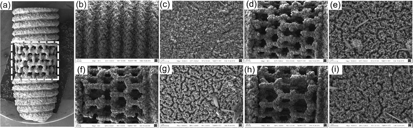
Figure 1(a) shows a general pattern of one kind of porous structured implant. The mid-piece area marked with a white frame is modified into 4 types of architecture (200, 350 and 500 μm pore sized and screw-typed structure). They are first observed with the SEM at low magnification (see Fig. 1b,d,f,h). At high magnification, numerous nano-sized burr-like structures can be seen on the implant surface. This is generated during the alkali heat treat- ment (mentioned later in the discussion section) to achieve a further nano-modification (see Fig. 1c,e,g,i). The herein employed LBM process is effective to achieve the desired titanium implant structural modification, as the implant pores remain open after.
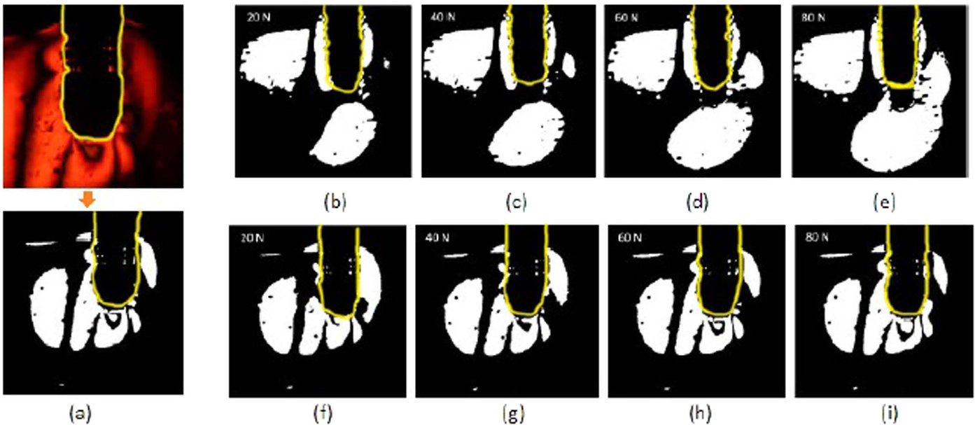
Photoelastographic study. Comparison between reference implant and 350 μm implant. As a highly con- centrated distribution of mechanical stress could affect the bone-to-implant interaction, we are interested to search for high order fringes around the examined implant. Fringe pattern is presented as black-white lines in a binary image, which is converted by applying threshold on the raw image histogram (see Fig. 2a). In analyzing the effect of loading on the reference implant, a comparative analysis of variance in different normal forces is per- formed. As shown in Fig. 2, the fringe pattern with highest intensity is found at the bottom of the implant. Also, isochromatic pattern with retardation phase of 1 is indicated around the screw thread at the implant neck. By comparing subfigure e) to b), the 1st order fringe pattern does not propagate further. However, it is seen in sub- figure e), that the 2nd fringe pattern starts to appear. The max. primary stress is 4.42 MPa (plotted from the pixel at the implant bottom site simulation model), located in the middle of the implant bottom site. Principally, the mechanical distribution is partially located around the screw thread on the reference dental implant. The placed normal force is relatively dispersed onto all positions around the dental implant.
3
In analyzing the effect of loading on the implant with 350 μm pore size, we find a totally different stress distri- bution. The fringe pattern with highest intensity is found at the bottom of the implant. When observing the fringe at the implant bottom, the oblique loading induces a significantly more densed stress distribution compared to the reference implant. It is seen in (Fig. 2i), that the 4th order fringe pattern is already generated, based on the recorded closed ring at the bottom site to represent the retardation phase 0. Compare to this, an isochromatic pattern with a lower retardation phase of 1 is indicated around the porous structure. The primary stress remains rather constant with the normal force changing from 20 to 80 N. According to the simulation results, the max.
primary stress is found in the bottom site of the implant bottom and reaches 4.65 MPa. It is higher than that in the reference implant. As the brief conclusion, the mechanical stress distribution is more conducted onto the implant bottom site, compared to that on the reference implant.
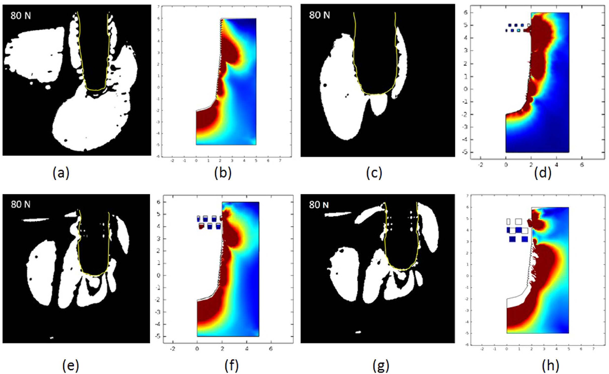
Comparison between porous structured implants. In analyzing the effect of loading on implants with 200 and 500 μm pore size (experimental and simulation results shown in Fig. 3), the results are leading to similar conclu- sions to that on 350 μm implant. The implant with 200 μm pores shows a similar fringe pattern to the reference implant. We find fringe pattern with higher retardation phase at the implant bottom. When comparing the 500 to 350 μm implant (or 350 to 200 μm), the fringe pattern at the implant bottom is showing a higher retarding phase in its fringe order. This represents the fact that the generated primary stress at the bottom sample site is becoming higher, when the porous structure size increases. The simulation results agree to the experimental results. For the Figure 1. (a) The general pattern of one kind of porous implant. The mid-piece area of all types of implants indicated by the white frame are further observed with the SEM. The SEM micrographs of (b), (c) reference screw type implant. Porous structured implant with pore size of 200 μm in (d), (e); 350 μm in (f), (g); 500 μm in (h), (i) at low (×30) and high (×10000) magnification respectively.
Figure 2. (a) The procedure of image post-processing converting a recorded elastograph into a binary image; Reference implant correlated to the fringe pattern under (b) 20, (c) 40, (d) 60, (e) 80 N; subfigure (f–i) parallely for fringe pattern on implant with 350 μm pore size. The manually sketched yellow line marks the layout of the implant.
4
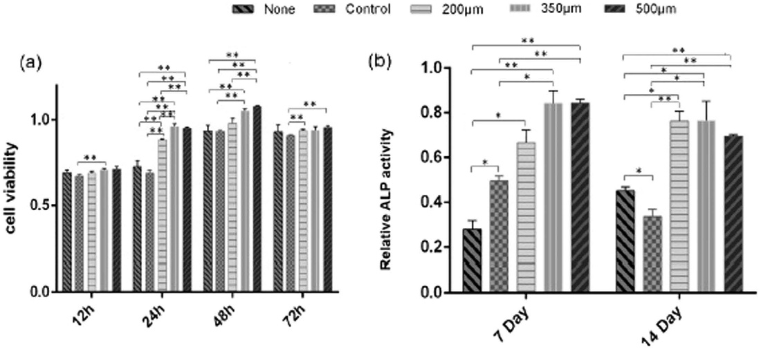
500 μm implant, we find a max. primary stress of 6.21 MPa at the bottom sample site. For the 200 μm implant, the value decreases to 4.37 MPa. Cell viability evaluation. MC3T3-E1, preosteoblast, is extracted from the mouse’s calvarial bone, which can be induced to mature osteoblast. The proliferation and differentiation of MC3T3-E1 cells on different types of implants are critical for bone tissue formation on the implants. CCK-8 assays show that MC3T3-E1 cells exhibit a significant increase in cell viability at 24 h and 48 h on 350 and 500 μm pore size structured implant, compared with all other groups at the same time period. In addition, statistical analysis shows a decrease in cell viability at 72 h due to the contact inhibition phenomenon probably (p < 0.05, see Fig. 4a).
The ALP activity of MC3T3-E1 cells on 350 and 500 μm pore size structured implant are higher than the values on the plate and that on the reference implant. The same conclusion can be drawn at day 7 and day 14. Furthermore, at day 14, the ALP activity of MC3T3-E1 cells of 200 μm group is increased compared to that on the reference implant (p < 0.05, see Fig. 4b). The porous structured implants enhance ALP levels to over 2 times higher than that of the reference implant. It is noticed that MC3T3-E1 cells on 350 and 500 μm pore always main- tain a better osteogenic activity until day 14, compared with the reference implant.
Figure 3. Fringe pattern under 80 N and the corresponding simulation results of (a), (b) reference implant; (c), (d) 200 μm implant; (e), (f) 350 μm implant; and (g), (h) 500 μm implant. The color calibration in the simulation results represents the relative stress from min. in blue to max. in red. The primary stress is plotted separately from the stationary studies.
Figure 4. (a) Cell viability (b) and ALP activity of MC3T3-E1 cells of each group at different time points, whereby *P < 0.05; **P < 0.01.
5
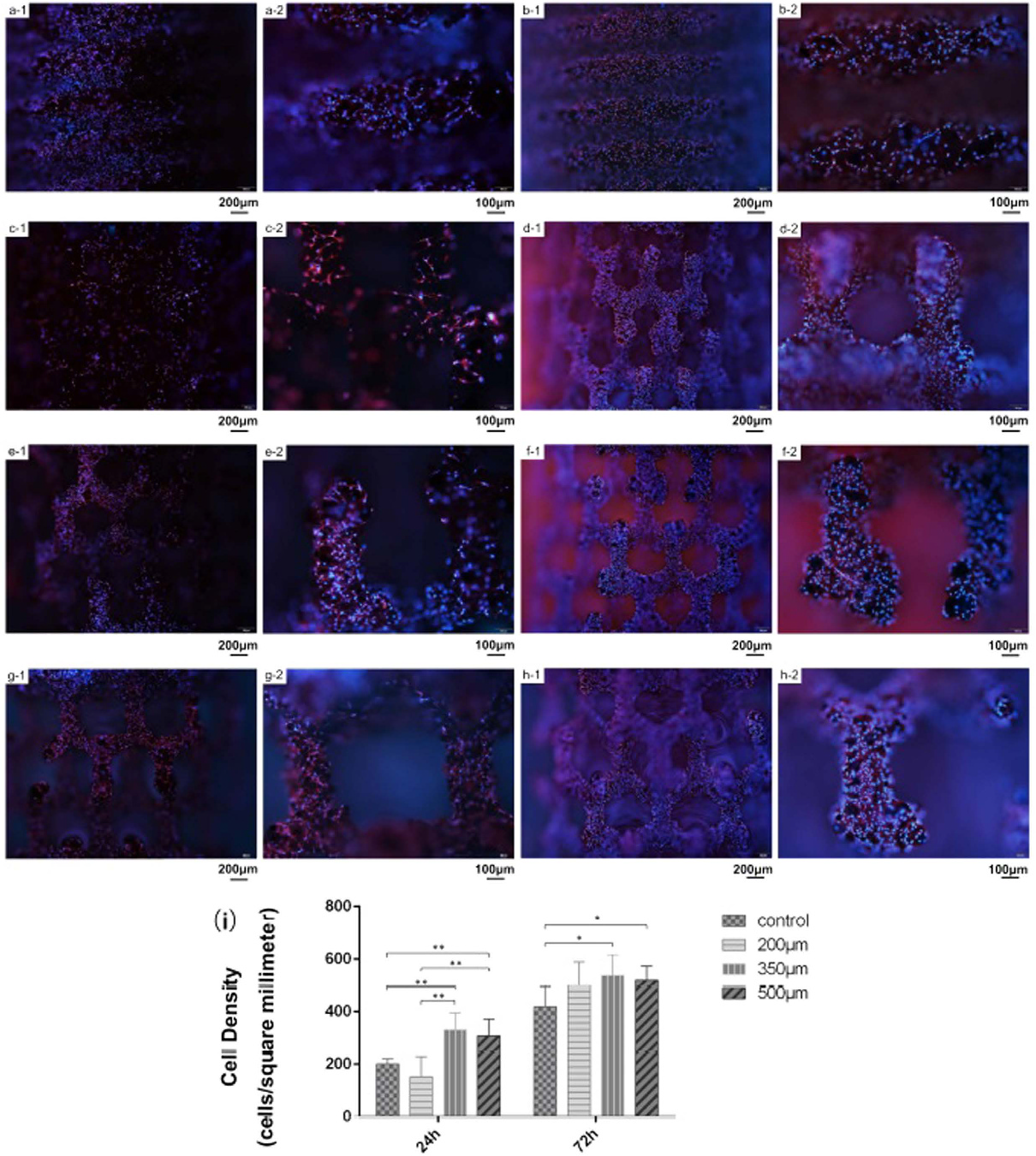
Cell observation and migration. The implant is impermeable to the light and is presented as a dark background under the optical microscope. The immunofluorescence makes MC3T3-E1 cells visible, when they attach to the implant surface. Figure 5 show the attached cells at 24 h (a-1, c-1, e-1, g-1: at low magnification; a-2, c-2, e-2, g-2: at high magnification) and 72 h (b-1, d-1, f-1, h-1, at low magnification; b-2, d-2, f-2, h-2, at high magnification).
The cell density (see Fig. 5i) increases with culture time for all groups of implants. The 35 and 500 μm pore size structured implants exhibit significant rise at 24 h, compared with all other groups. The quantitative results of cell density are verifying the cell viability test indicated hereinabove. MC3T3-E1 cells on 350 and 500 μm pore size structured implants show a high density of 331.6 and 308.5 cells/mm2 respec- tively at 24 h. This is more than that of the reference implant and 200 μm group. At 72 h, the 350 and 500 μm pore size structured implants (538.1 and 512.4 cells/mm2 respectively) statistically show a higher cell density than the control group (418.5 cells/mm2). Meanwhile, the cell density of the 200 μm group increases to 499.6 cells/mm2, which approaches to the other two porous structured group. In general, a higher density of MC3T3-E1 cells are attached on the porous structured implants, compared with the screw-typed implant along with the culturing time.
Figure 5. Attached MC3T3-E1 cells showed by immunofluorescence after co-cultured with different type of implant for 24 h and 72 h. Typical images of control group (a-1, a-2) for 24 h and 72 h (b-1, b-2) at low (× 40) and high (×100) magnification; 200 μm group (c-1, c-2) for 24 h and 72 h (d-1, d-2) at low (×40) and high (×100) magnification; 350 μm group (e-1, e-2) for 24 h and 72 h (f-1, f-2) at low (×40) and high (×100) magnification; 500 μm group (g-1, g-2) for 24 h and 72 h (h-1, h-2) at low (×40) and high (×100) magnification.
i) Cell density of MC3T3-E1 cells attached on different type of implant at each time points. *P < 0.05; **P < 0.01.
6
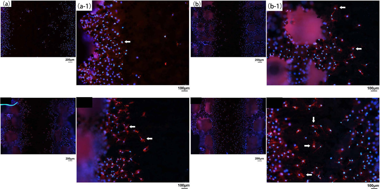
Since the implant is semiterete, the back side of the implant does not contact with MC3T3-E1 cells at the beginning. After cells anchore to the implant surface, they begin to migrate to the back side. From Fig. 6, there are few cells observed at the central axis of the control (a, a-1), 200 μm (b, b-1) and 350 μm (c, c-1) group of implant on day 7, while more amount of cells are found at the central axis of the 500 μm pore size structured implant (d, d-1). Furthermore, the back side of all types of the porous architecture are covered with dense MC3T3-E1 cells. At a high magnification, more spindle and fibrous shaped cells (indicated by the white arrows) are attached to the porous structured implant, whereas the porous structure gives the cells a more stretched shape than the reference implant according to our understanding.
Figure 6. Attached MC3T3-E1 cells at the back side of different type of implant on Day 7. Few cells has migrated to the central axis of the control (a, a-1 for high magnification); 200 μm (b, b-1 for high magnification); 350 μm (c, c-1 for high magnification) group of implant. Plenty of MC3T3-E1 cells can be observed at the central axis of 500 μm pore sized implant (d, d-1 for high magnification). White arrows show the typical morphology of the attached MC3T3-E1 cells on each type of implant.
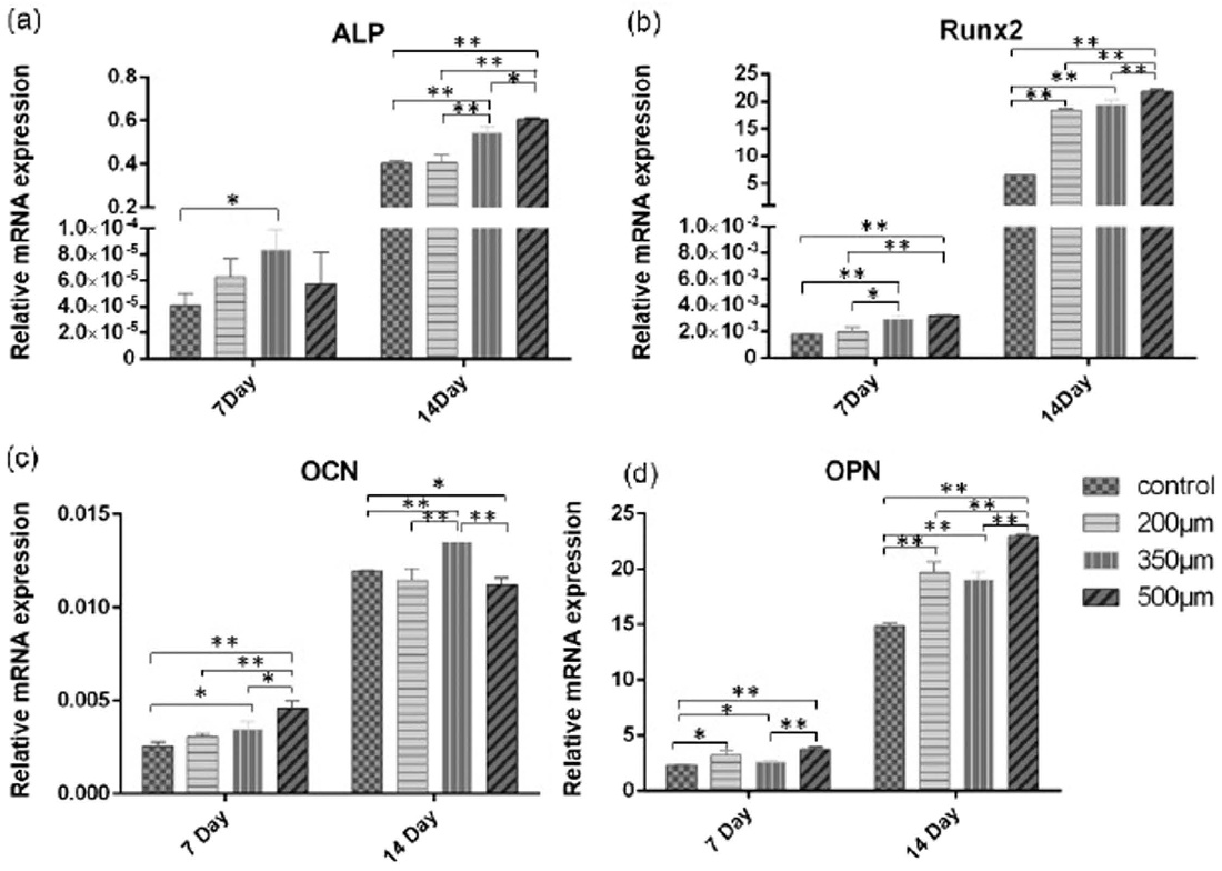
Figure 7. Relative mRNA expression of ALP in (a); Runx2 in (b); OCN in (c); and OPN in (d), whereby
Related Journal Articles & DOI Links
Selected peer-reviewed publications relevant to 12 Lead ECG Acquisition. Click the DOI to access the full paper (may require institutional access).
-
1. Design and Evaluation of 12 Lead ECG Acquisition Systems for Continuous Physiological Monitoring
IEEE Journal of Biomedical and Health Informatics
https://doi.org/10.1109/JBHI.2020.2981234 -
2. Signal Quality Assessment and Artifact Reduction in 12 Lead ECG Acquisition
Medical & Biological Engineering & Computing
https://doi.org/10.1007/s11517-020-02145-6 -
3. Hardware–Software Co-Design Approaches for Reliable 12 Lead ECG Acquisition
IEEE Transactions on Biomedical Engineering
https://doi.org/10.1109/TBME.2019.2895762 -
4. Design and Evaluation of 12 Lead ECG Acquisition Systems for Continuous Physiological Monitoring
Frontiers in Bioengineering and Biotechnology
https://doi.org/10.3389/fbioe.2020.00123 -
5. Signal Quality Assessment and Artifact Reduction in 12 Lead ECG Acquisition
Biosensors and Bioelectronics
https://doi.org/10.1016/j.bios.2021.112345 -
6. Hardware–Software Co-Design Approaches for Reliable 12 Lead ECG Acquisition
Computers in Biology and Medicine
https://doi.org/10.1016/j.compbiomed.2021.104567 -
7. Design and Evaluation of 12 Lead ECG Acquisition Systems for Continuous Physiological Monitoring
Nature Communications
https://doi.org/10.1038/s41467-020-12345-6
Why Choose Us?
Bangalore guidance for robotics, Spectre and autonomous systems projects.
Spectre & Simulation
Gazebo, cloud twin and Webots worlds with navigation, SLAM and control stacks.
Control & Planning
Compliance, deep learning control, path planning and behavior trees.
Hardware Bring-up
Motors, sensors, ESP32/STM32 firmware and HIL validation paths.
Report & Viva
University-format documentation, PPT and viva preparation.
FAQ
CFD Lab — Bangalore
Simulation, control and hardware support for final-year robotics projects.
Stacks
Worlds
Digital Twin
Control
Robots
Offline
Bring-up