B
ioelectronic modulation of neural activity is a powerful tool for treating many disorders, especially when these disorders cannot be effectively managed with conventional therapies.
For example, electronic devices that stimulate neural activity are effective for treating disorders such as Parkinson’s Disease, epi- lepsy, chronic pain, hearing loss and paralysis1–7. These devices are most effective when implanted in the body where they can selec- tively stimulate the desired nerve targets; however, the invasiveness of the implantation can introduce additional risk for the patient.
Invasive implants can also lead to complications such as chronic inflammation, which can further degrade device functionality and lead to failure8–10.

The vascular system that accompanies nerves as part of the neu- rovascular bundle provides a less invasive route for approaching nerve targets11. Existing neural implants for nerve targets such as the dorsal root ganglion (DRG) can suffer from site infection that results in device explantation and follow-up surgeries12. Millimetre-sized endovascular neural stimulators (EVNS) delivered via an intra- vascular catheter to deep tissue targets with a minimally invasive procedure through the blood vessels within the body would leave the target tissue undisturbed. As a result, endovascular deployment of devices is often associated with lower risk compared with open surgical approaches: recovery times are drastically reduced and site infections are extremely uncommon11. Given these advantages, an endovascular approach to neural stimulation would be attractive for the multitude of central and peripheral nerve targets that are adjacent to vascular structures, such as targets in the deep brain, peripheral nerves and the heart13–15. Recently, several new endovas- cular bioelectronic devices that exemplify the benefits of stimulat- ing neural tissue through the vasculature have been developed16–19.

However, these devices have stimulation leads that are wired to pulse generators or centimetre-sized inductive coils. The long lead wires and implantation of centimetre-sized devices create addi- tional failure points and require an open surgery that reduces some of the benefits of an endovascular surgical approach20.
By miniaturizing the bioelectronic implants to a diameter of a few millimetres, it would be possible to deliver endovascular neuro- modulation therapies entirely with minimally invasive procedures that rely on percutaneous catheters. To sufficiently miniaturize the device to the size constraints of the catheter (<3 mm diameter), some form of wireless power is necessary to replace the bulkier batteries if we expect long-term operation. While several innova- tive wireless power transfer modalities have been demonstrated, including far-field radio frequency radiation, near-field inductive coupling, mid-field electromagnetics with hybrid inductive and radiative modes, ultrasound and light, there has yet to be a demon- stration of a mm-sized wireless and digitally programmable neural stimulator that operates at a depth of several centimetres in a large animal model21–36.
Here we turn to magnetoelectrics (ME) as a wireless data and power transfer technology due to its large power densities, high tol- erance for misalignment and ability to operate in deep tissue when A wireless millimetric magnetoelectric implant for
The Endovascular Stimulation Of Peripheral Nerves
Joshua C. Chen1,15, Peter Kan2,15, Zhanghao Yu3,15, Fatima Alrashdan 3, Roberto Garcia 2, Amanda Singer3,4, C. S. Edwin Lai1, Ben Avants3, Scott Crosby5, Zhongxi Li6, Boshuo Wang 7, Michelle M. Felicella8, Ariadna Robledo2, Angel V. Peterchev 6,7,9,10, Stefan M. Goetz 6,7,9,11, Jeffrey D. Hartgerink 1,12, Sunil A. Sheth 13 ✉, Kaiyuan Yang 3 ✉ and Jacob T. Robinson 1,3,4,14 ✉ Implantable bioelectronic devices for the simulation of peripheral nerves could be used to treat disorders that are resistant to traditional pharmacological therapies. However, for many nerve targets, this requires invasive surgeries and the implantation of bulky devices (about a few centimetres in at least one dimension). Here we report the design and in vivo proof-of-concept testing of an endovascular wireless and battery-free millimetric implant for the stimulation of specific peripheral nerves that are difficult to reach via traditional surgeries. The device can be delivered through a percutaneous catheter and leverages mag- netoelectric materials to receive data and power through tissue via a digitally programmable 1 mm × 0.8 mm system-on-a-chip.
Implantation of the device directly on top of the sciatic nerve in rats and near a femoral artery in pigs (with a stimulation lead introduced into a blood vessel through a catheter) allowed for wireless stimulation of the animals’ sciatic and femoral nerves. Minimally invasive magnetoelectric implants may allow for the stimulation of nerves without the need for open surgery or the implantation of battery-powered pulse generators.
Nature Biomedical Engineering | VOL 6 | June 2022 | 706–716 | www.nature.com/natbiomedeng
Nature Biomedical Engineering
compared with alternative wireless power technologies for bioelec- tronic implants37,38. Our results show that it is possible to safely stimulate periph- eral nerves using electrodes placed inside the blood vessels, and that we can deliver the stimulation using a mm-sized bioelec- tronic implant. By combining ME data and power delivery with a custom application-specific integrated circuit (ASIC), we achieve a miniature device that is only 3 × 2.15 × 14.8 mm when fully encapsulated. Compared with miniature ultrasound-powered devices, our MagnetoElectric-powered Bio ImplanT (ME-BIT) maintains functional power levels over a larger range of trans- lational and angular misalignment, and does not need ultra- sound gels or foams to couple energy from the transmitter29,31–33.
Furthermore, in comparison with previous in vivo demonstra- tions of ME-powered devices that were not digitally program- mable37, the ME-BIT technology described here can receive digital data via the ME effect to programme the amplitude and timing of the electrical stimulus. As proof-of-concept, we show that these ME-BITs can be powered several centimetres below the tissue surface and can electrically stimulate peripheral nerve targets through the vasculature in a large animal model. These proof-of-principle studies open the door to minimally invasive bioelectronic therapies based on EVNS.
Results
ME combined with a custom ASIC enables a mm-sized neural stimulator. To overcome the challenge of wireless data and power delivery to miniature bioelectronic implants, we developed a data and power delivery system on the basis of ME, which achieves high power densities within the safety limits for human expo- sure39. ME materials provide efficient power delivery for bioelec- tronic implants by directly converting magnetic fields to electric fields on the basis of the material’s properties37,40. In our case, we use a laminated bilayer material that consists of Metglas, a mag- netostrictive layer, and lead zirconium titanate (PZT), a piezo- electric layer. When we apply a magnetic field to the material, the magnetostrictive material generates a strain that is coupled to the piezoelectric layer that, in turn, generates an electric field37.
Thus, by applying an alternating magnetic field at the acoustic resonant frequency of the film, we can efficiently deliver power to our implant37–39,41,42. In addition to delivering power, we can also transmit data to our implant by modulating the frequency of the applied magnetic field. The frequency shift results in a change in the amplitude of the received voltage, which can be interpreted as a digital bit sequence that specifies the stimulation parameters for the implant41,42. Taken together, the complete wireless EVNS system consists of an external magnetic field transmitter, an ME film that harvests power and data from the magnetic field, and a custom integrated circuit (IC) that interprets the digital data and generates the electrical stimulus delivered by the electrodes (Fig.
1a). Figure 1b shows a conceptual overview of the system imple- mented in a large animal model where a surface coil can be used to wirelessly transmit a magnetic field to power and programme the implant for endovascular stimulation.
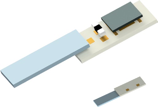
The ME-BIT itself consists of a magnetoelectric film with a size of 1.75 mm × 5 mm and a thickness of 0.3 mm for wireless power and data transfer, an ASIC for modulating the ME power and stimulation, and an external capacitor for energy storage (Fig. 1c), the system being packageable to fit within an 11 French catheter.
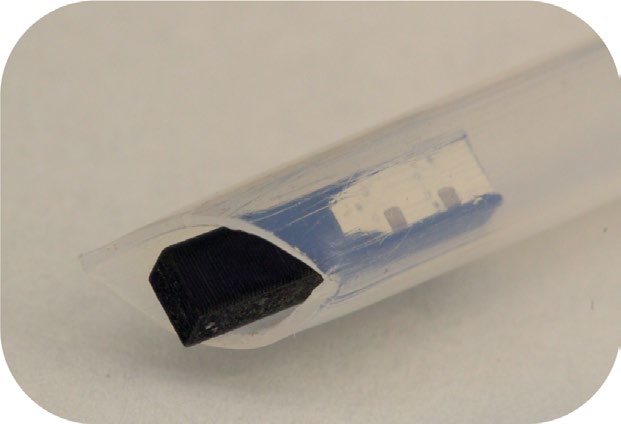
For our experiments, we packaged the ME-BIT within a custom three-dimensionally (3D) printed polylactic acid capsule with on-board electrodes that can also be used to power external elec- trodes (Fig. 1d). With this design, the miniature capsule can not only be delivered through a minimally invasive catheter, but also serve as a complete neuromodulatory device that can receive power, undergo programming and transmit stimulation to neural tissue.
A custom magnetic field transmitter enables data and power transfer at centimetre depths within safety limits. To deliver data and power to the implant, we designed a magnetic field transmitter that drives a high-frequency biphasic current into a resonant coil41.
By maintaining transmitter power levels below 1 W, we can achieve field strengths >1 mT, sufficient to power the ME-BIT at depths of 4 cm within the safety limits.
Because the amplitude of the ME voltage peaks at the acoustic resonant frequency, we can send digital signals to our ME-BIT by detuning the applied magnetic field frequency. Figure 2 shows our communication protocol with charging, data transfer and stimu- lation phases. As seen in Fig. 2b, we can select 3 frequencies to transmit digital data. The first frequency ‘Data 1’ corresponds to the mechanical resonance (345 kHz). This is the frequency of maxi- mum voltage (and maximum power transfer), which we use as a digital 1, and for the charging and stimulation phases. The second frequency ‘Data 0’ is detuned by ~5 kHz. This frequency of 350 kHz produces a lower amplitude voltage, which is used as a digital 0.
The third frequency is detuned by 55 kHz from the resonance peak and produces an even lower voltage than the ‘Data 0’ signal. This ‘notch frequency’ of 400 kHz is used to indicate the start of the data transfer and stimulation phases. By using the mechanical properties of the ME film to receive data on the basis of frequency modula- tion, we can avoid turning the transmitter coil on and off, which would require a settling time of 100 µs for our resonant transmitters.
Given the fast settling time of this frequency modulation scheme, we find that 64 cycles of the carrier frequency can reliably trans- mit one bit, resulting in a 4.6 kbps data rate. We use a digital pay- load of 18 bits per stimulation, which accounts for a preamble and real-time calibration of the demodulation reference. This payload combined with the charging phase yields a maximum stimulation rate of 1 kHz, which is well within the range of typical neural stimu- lation applications41.
We estimate that this device can generate a maximum of 4 mW as long as the ME films can maintain a peak resonance voltage of >8 peak-to-peak voltage (Vpp) with a resistive source impedance lower than 1 kΩ (Fig. 2d). This power level is sufficient for many neural stimulation applications43.
Custom IC provides digitally programmable stimulation with <9 µW power consumption. To deliver reliable stimulation inde- pendent of the coupling between the transmitter and the ME-BIT, the implant includes a custom ASIC that uses the digitally received data to programme the shape (monophasic or biphasic), the amplitude (0.3 V to 3.3 V with 4 bit resolution), the pulse width (0.05 ms to 1.2 ms with 3 bit resolution) and the delay (0.01 ms to 0.8 ms) of the stimulation.
The stimulation reference voltage is also programmed by the down- link data to generate a stimulation supply voltage 10% higher than the desired amplitude. As a result, the implant achieves >90% stimula- tion efficiency ηstim for 1.5–3.3 V stimulation amplitude; when com- pared to the stimulation power (<9 mW), the power consumption of the SoC is negligible (<9 µW). Thus, we expect little heating due to energy loss on the chip. Furthermore, this high efficiency also reduces required transmitter power and its associated heating.
< Stimulation Voltage > × < Stimulation Current >
< stimulation supply voltage > × < stimulation current >
Complementary
metal-oxide-semiconductor (CMOS) technology (TSMC), mea- sures only 1 mm × 0.8 mm while performing several functions to ensure robust stimulation and communication. The ME-induced alternating voltage is first rectified to the direct current (DC) voltage Vrect by a full-bridge active rectifier with an 84% voltage conversion efficiency. This rectified voltage is then converted by a DC voltage converter, which provides proper voltage and buffers energy on the Nature Biomedical Engineering | VOL 6 | June 2022 | 706–716 | www.nature.com/natbiomedeng
Nature Biomedical Engineering
off-chip capacitor Cstore for stimulation. The voltage converter also generates a high-voltage supply VDD_H for other circuits for power management, including the low-dropout regulator and the voltage references generator, and guarantees cold startup of the system as well. A constant low-voltage supply VDD_L of 1 V is provided by the low-dropout regulator for the controller, the data demodulator and the timing reference generator. To ensure proper system operation, a power-on-reset (POR) signal is triggered when VDD_L stabilizes.
To maintain reliable functionality of implants under varying ME voltages caused by changes in transmitter–implant distance and alignment, the phase transitions of the IC are fully controlled by the transmitter through the short notches in ME voltage. In addi- tion, the demodulation threshold for the amplitude-modulated data is generated autonomously at the beginning of the data transmis- sion cycle to avoid data recovery errors due to changes in ME volt- age. Meanwhile, a global system clock is extracted from the source by a low-power comparator-based clock recovery circuit, ensuring process and voltage invariant timing references for data sampling and stimulation.
ME implant demonstrates high tolerance towards misalign- ment. We find that our magnetoelectric-based power transfer approach displays improved tolerance for translational and angular misalignment when compared with other mm-sized implants.
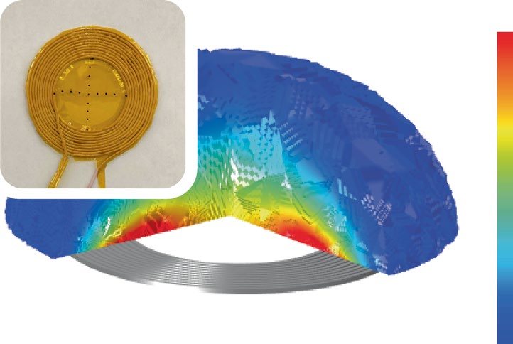
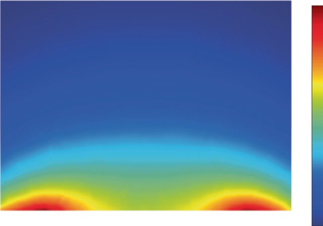
Our simulations show that ME-BITs can tolerate approximately 3 cm translational misalignment from the centre of the transmitter coil and a depth of 3 cm in tissue. Using finite element modelling (COMSOL) to model the magnetic field generated by our 15-turn transmitter coil, we find an almost uniform magnetic field across 6 cm inner diameter of the coil (>70% of total transmitter area) as shown in Fig. 3a. The dashed line in Fig. 3b shows the boundary line of 1 mT, which is the operating field strength for the implant.
When we tested our 15-turn transmitter coil, we found that we could indeed power our ME films above our operating voltage (>3.6 Vpp) a distance of 3 cm in air from the surface of the coil, with a misalignment tolerance that matched the 6 cm inner diameter of the coil (Fig. 3c). This misalignment tolerance is more than 27 times greater than recently reported ultrasound-powered implants with a mm-scaled translational window33. The improved alignment toler- ance would be advantageous for applications where an individual may want to align a transmitter several times a day or fit a wearable transmitter that may move and drift over time.
Furthermore, ME-based power transfer also demonstrates encouraging angular misalignment tolerances. In comparison with inductive coils that harvest power on the basis of magnetic flux, the ME materials harvest power on the basis of magnetic
Off-Chip Capacitor
Fig. 1 | Overview of the wireless magnetoelectric endovascular neural stimulator. a, The overall EVNS system includes a magnetic field driver connected to a resonant coil that is tuned to the ME film resonant frequency. The coil outputs a frequency modulated magnetic field and switches between three different frequencies to modulate data and power received by the ME-BIT implant. The magnetic field is converted to an electric field by the magnetoelectric film. Specifically, the magnetostrictive layer Metglas mechanically deforms under the magnetic field and transfers the resulting strain to the piezoelectric layer PZT and induces a voltage. The amplitude of the voltage is then modulated by shifting the frequency of the applied field. The resulting voltage modulation received by the ME-BIT programmes the custom IC to output the desired stimulus waveform. b, For our proof-of-concept experiments, the ME-BIT is implanted proximally to a blood vessel deep within tissue and wirelessly powered through a magnetic coil in a pig. The implant’s stimulation lead is introduced into the vessel to stimulate nearby nerve targets. c, A rendering of the implant is shown with all the external components, including the system on a chip (SoC), external capacitor and the ME transducer. d, Photograph of the fully packaged device inside a 3D-printed capsule resting in a clear sheath. The implant is encapsulated with a non-conductive epoxy before being implanted into the body and has the potential to be delivered endovascularly.
Nature Biomedical Engineering | VOL 6 | June 2022 | 706–716 | www.nature.com/natbiomedeng
Nature Biomedical Engineering
field strength. As a result, it has been shown that ME demon- strates more stable power transfer as a function of angular mis- alignment39. This angular stability is supplemented by the fact that the large magnetic permeability of the Metglas layer helps to con- centrate the magnetic field lines along the length of the ME film44.
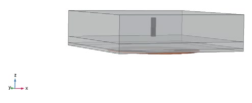
To assess the angular tolerance of the ME-BIT in vivo, we used a COMSOL model to simulate how ME voltage is affected when it undergoes angular misalignment in tissue (see Methods). Because the simulated coil is radially symmetrical, we found that rotating the film in either the θ direction, as shown in Fig. 3d, or in the φ angular direction, resulted in the ME voltage decaying simi- larly with either angular change and being able to maintain >40% of the maximum voltage at a 90° rotation. Existing devices and implants that use ME antennas probably share similar angular tol- erances and have been shown to be operational at large distances; however, these sub-mm devices primarily operate at much higher frequencies (60 MHz to 2.5 GHz)45–47. At these higher frequencies, tissue absorption and reflection become more substantial, which lowers the amplitude of the field that can be applied within the safety limits48. Furthermore, many of these demonstrations rely on the magnetic component of radiating electromagnetic waves, which is small compared to the electric field component. As a result, small ME devices that couple to radiating electromag- netic waves are used primarily for low-power sensing and com- munication applications rather than electrical stimulation, which requires more power.
42 Bits
Header: demod.
0
Fig. 2 | Timing and functional diagram for the ME-BIT. a, Timing diagram of the operation of the implant. The implant cycles through charging, data transfer and stimulating phase. The off-chip capacitor is charged in the charging phase to store energy for the stimulation. In data transfer, downlink data is received and demodulated by the ASIC to programme stimuli. The operation of the implant is fully controlled by the transmitter through frequency modulation, which changes the carrier frequency of the magnetic field for different induced voltages of the ME film. b, The peak-to-peak voltage for a film resonating in an extensional vibration mode at 345 kHz as a function of magnetic field frequency. Three different field frequencies are chosen for communication with the SoC. Data 1 indicates the highest voltage which is used for the charging phase and for encoding ‘data 1’. Shifting the frequency by 5 kHz results in a 25% drop in Vpp that is used for ‘data 0’ as can be seen in the data packet highlighted in red. The third frequency or notch frequency is chosen at a > 50 kHz shift, which causes the Vpp to drop > 85%. This is used to signify the beginning and end of the data transfer phase. c, The low film impedance at resonance lies at ~700 Ω to support milliwatt level power budgets. d, A summary of the data payload, including the header for demodulation threshold calibration and bits used for programming stimulation amplitude, delay and pulse width. e, Block diagram of the magnetic transmitter (left) and the custom ASIC of the implant (right). The magnetic transmitter contains a controller that interfaces with a personal computer (PC), a magnetic field driver and a resonant magnetic coil to generate a low-frequency alternating magnetic field. The ASIC interfaces with an ME film to wirelessly receive power and data, and consists of power management, data recovery, control and stimulation modules to drive programmable stimulation. Energy for the high-power stimulation is stored in the off-chip capacitor and stimulus is delivered through the on-board electrodes.
Nature Biomedical Engineering | VOL 6 | June 2022 | 706–716 | www.nature.com/natbiomedeng
Nature Biomedical Engineering
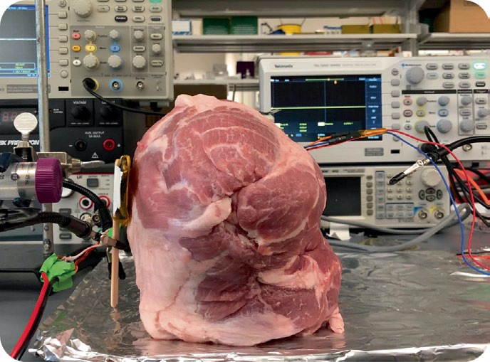
ME power is able to sustain operation of implant at centime- tre distances within tissue. We found that the ME-BITs received enough power to function when implanted at centimetre depths in porcine tissue (Fig. 3e). Specifically, the ME film packaged inside the IC capsule was able to power the IC and maintain a sustained rectified voltage of 1.9 V. By adjusting the magnetic field while increasing the distance between the implant and transmitter coil, the ME-BIT was able to maintain a working voltage up to 4 cm (Supplementary Table 1). This energy was delivered through a ~3 mm air gap between the surface coil and tissue, demonstrating the ability to achieve non-contact wireless power transfer.
When characterizing the power coupling efficiency in tissue, we achieved functional power levels at a transmitter-receiver (TX-RX) distance of up to 4 cm, which is primarily limited by the size and power level of our magnetic field transmitter. At the surface of the coil, while the ME-BIT generated a peak power of 1.17 mW, the resulting peak efficiency of the implant was found to be 4.4% (Fig.
3f). To maintain a functional voltage on the implant at a depth of 4 cm, the coil current was increased from 0.23 A to 8.6 A at 0 mm and 40 mm distance, respectively (Supplementary Table 1 and Methods). While the maximum distance demonstrated here is 4 cm, ME voltage is primarily dependent on magnetic field strength, thus
Rectified Voltage
Fig. 3 | Characterization of ME power transfer. a, Finite element simulation of the magnetic field produced by one of the AC coil geometries used to power the ME implants. The coil shown is ~7 cm in diameter, made from 18 AWG litz wire and insulated with polyimide tape. The ME implant has been shown to maintain functional voltages at a field of 1 mT, and the COMSOL simulation demonstrates the space in which the implant remains functional where the edges are bound to be 1 mT. b, A 2D cross-section of the simulation from b is shown, where a 1 mT field can be generated at a distance of 30 mm and maintain lateral uniformity in case of translational misalignment (red dashed line). c, Experimental data measuring the implant’s rectified voltage (left) as the implant is moved away from the centre of the coil. For the device to remain functional, the rectified voltage needs to be >1.8 V as shown with the red dotted line. Also shown is the peak-to-peak ME voltage (right). d, COMSOL simulation of the ME-BIT placed within a layered block of tissue (20 mm muscle, 5 mm fat, 2 mm skin) is used to model angular misalignment tolerances in vivo for both θ and φ angular rotations.
e, An experimental image is shown for an ex vivo model of porcine tissue. The magnetic field transmitter which is a combination of both the permanent magnet and AC coil, is placed on the left-hand side of the tissue. The encapsulated ME film powers an implant up to 40 mm within the heterogeneous tissue, while the rectified voltage of the implant is measured and used to calculate the power transfer efficiency. f, Measured PTE for the ME implant as a function of distance in tissue. At an operating distance of 30 mm, the transmitter power was ~6 W to maintain the 1.17 mW implant power, yielding a 0.01% efficiency.
Nature Biomedical Engineering | VOL 6 | June 2022 | 706–716 | www.nature.com/natbiomedeng
Nature Biomedical Engineering
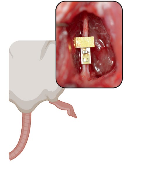
greater TX-RX distances may be achieved by optimizing driver elec- tronics and transmitter designs. ME-BIT demonstrates programmability and fully untethered operation for direct nerve stimulation in rats. Proof-of-concept experiments show that wirelessly powered ME-BITs evoke repeat- able compound muscle action potentials (CMAPs) along with observable leg kicks when placed in contact with the sciatic nerve. This miniaturized implant had a volume of 6.2 mm3 and weighed 30 mg, making this suitable for small rodent models, and was able to directly stimulate rat peripheral nerve (n = 2) in vivo (Fig. 4a). Stimulation for rat A, while the mote was fully unteth- ered and powered at a distance of 1 cm, is shown in Fig. 4b, where a 3 V, 1.5 ms pulse width monophasic pulse train was applied at 3 Hz. Electromyography recordings of foot muscles showed wave- forms that were time locked with the applied stimulus at the same frequency. Often necessary in neural interfaces, the stimulation parameters on the ME-BIT can be adjusted by sending the appropri- ate commands through the magnetic field. Not only is the implant able to adjust its stimulation amplitude from 0.3 V to 3.3 V as shown in Fig. 4c, it is also able to vary its pulse width and frequency to meet the demands of different neuromodulation applications and provide targeted therapies to account for variance from patient to patient. The programmability of the device is shown through an acute demonstration with rat B by varying the amplitude of the stimulus and observing the resulting graded EMG response. By adjusting the stimulation as well as the pulse width, the total charge delivered to the nerve could be controlled to directly affect the num- ber of recruited motor units to elicit varying CMAP responses. In Fig. 4d, we innervated the sciatic nerve with monophasic pulses at 1 Hz while holding the pulse width at 1.5 ms and varying the amplitude from 300 mV to 3.1 V. The resulting CMAPs ranged in amplitude from 0.4 to 2.7 mV where the number of recruited muscle fibres seemed to saturate when increasing the stimulation amplitude from 2.1 to 3.1 V.
The ME system demonstrates wireless endovascular nerve stim- ulation for multiple nerve targets. To demonstrate endovascular neural stimulation and the potential for clinical translation, we implanted the ME-BIT in a pig and demonstrated peripheral nerve stimulation from within the blood vessels using a wirelessly powered device. For this experiment, the film was mounted along the printed circuit board (PCB) and soldered to gold pads, with the stimulation lead wire soldered to an exposed pad on the top of the PCB before the device encapsulation (Fig. 5a). For the surgery, an incision was made in the hind leg of the pig to expose both the femoral nerve and the femoral artery. The ME implant was then placed into the surgical site and a 9 Fr sheath was then introduced into the femoral artery to allow access into the vessel. The parylene insulated stimulation wire connected to the implant was introduced into the vessel as shown in the schematic in Fig. 5b. Images of the surgical site shows the femo- ral nerve and a sheath entering the femoral artery with the encap- sulated implant placed proximal to the vessel. The magnetic field transmitter was then brought to the surface of the skin to wirelessly power the implant at an implanted distance of 1.5 cm (Fig. 5d). By applying a 3 V monophasic stimulus pulse with 1.5 ms pulse width to the exposed tip of the endovascular wire, the device provided tar- geted monopolar stimulation with the reference electrode on the ME implant. As shown in Fig. 5c, we were able to stimulate the femoral nerve through the femoral artery at various stimulation frequencies
0.3 V
Fig. 4 | In vivo direct nerve stimulation in a rat model. a, Schematic of the implantation of a fully wireless ME-BIT in a rat model. The device is placed on top of the rat sciatic nerve and wirelessly powered from an external transmitter. The stimulating electrodes are two 1 mm × 1 mm gold pads spaced 2 mm apart on the bottom side of the circuit board. EMG recording electrodes are placed in the plantar muscles of the foot while a ground electrode is placed higher in the body. Also shown is an image of the actual device used for stimulation. b, The free-floating device is set to stimulate the nerve at 3 Hz with 3 V, 1.5 ms pulses and the recorded EMG signal is shown. The insert shows a close-up of the highlighted EMG trace. c, A graph showing programmed biphasic stimulus pulses of varying amplitudes. d, Averaged EMG recordings from the plantar muscles of the rat showing graded traces in response to varying levels of programmed stimulation powered by the wireless implant.
Nature Biomedical Engineering | VOL 6 | June 2022 | 706–716 | www.nature.com/natbiomedeng
Related Journal Articles & DOI Links
Selected peer-reviewed publications relevant to 12 Lead ECG Acquisition. Click the DOI to access the full paper (may require institutional access).
-
1. Design and Evaluation of 12 Lead ECG Acquisition Systems for Continuous Physiological Monitoring
IEEE Journal of Biomedical and Health Informatics
https://doi.org/10.1109/JBHI.2020.2981234 -
2. Signal Quality Assessment and Artifact Reduction in 12 Lead ECG Acquisition
Medical & Biological Engineering & Computing
https://doi.org/10.1007/s11517-020-02145-6 -
3. Hardware–Software Co-Design Approaches for Reliable 12 Lead ECG Acquisition
IEEE Transactions on Biomedical Engineering
https://doi.org/10.1109/TBME.2019.2895762 -
4. Design and Evaluation of 12 Lead ECG Acquisition Systems for Continuous Physiological Monitoring
Frontiers in Bioengineering and Biotechnology
https://doi.org/10.3389/fbioe.2020.00123 -
5. Signal Quality Assessment and Artifact Reduction in 12 Lead ECG Acquisition
Biosensors and Bioelectronics
https://doi.org/10.1016/j.bios.2021.112345 -
6. Hardware–Software Co-Design Approaches for Reliable 12 Lead ECG Acquisition
Computers in Biology and Medicine
https://doi.org/10.1016/j.compbiomed.2021.104567 -
7. Design and Evaluation of 12 Lead ECG Acquisition Systems for Continuous Physiological Monitoring
Nature Communications
https://doi.org/10.1038/s41467-020-12345-6
Why Choose Us?
Bangalore guidance for robotics, Spectre and autonomous systems projects.
Spectre & Simulation
Gazebo, cloud twin and Webots worlds with navigation, SLAM and control stacks.
Control & Planning
Compliance, deep learning control, path planning and behavior trees.
Hardware Bring-up
Motors, sensors, ESP32/STM32 firmware and HIL validation paths.
Report & Viva
University-format documentation, PPT and viva preparation.
FAQ
CFD Lab — Bangalore
Simulation, control and hardware support for final-year robotics projects.
Stacks
Worlds
Digital Twin
Control
Robots
Offline
Bring-up