(Fes)
systems are successful in restoring motor function and supporting paralyzed users. Commercially available FES products are open loop, meaning that the system is unable to adapt to changing conditions with the user and their muscles which results in muscle fatigue and poor stimulation protocols. This is because it is difficult to close the loop between stimulation and monitoring of muscle contraction using adaptive stimulation. FES causes electrical artefacts which make it challenging to monitor muscle contractions with traditional methods such as electromyography (EMG). We look to overcome
Mechanomyographic (Mmg) Sensors To Be Able To
monitor muscle activity during stimulation in real time. To provide a meaningful task we built an FES cycling rig with a software interface that enabled us to perform adaptive recording and stimulation, and then combine this with sensors to record forces applied to the pedals using force sensitive resistors (FSRs); crank angle
Position Using A Magnetic Incremental Encoder And
inputs from the user using switches and a potentiometer. We illustrated this with a closed-loop stimulation algorithm that used the inputs from the sensors to control the output of a programmable RehaStim 1 FES
Stimulator (Hasomed) In Real-Time. This Recumbent
bicycle rig was used as a testing platform for FES cycling. The algorithm was designed to respond to a
Change In Requested Speed (Rpm) From The User And
change the stimulation power (% of maximum current mA) until this speed was achieved and then maintain it.
I. Introduction
Functional Electrical Stimulation (FES) systems enable muscles to be contracted even though the neurological path to the brain through the spine has been broken . Although the primary intent of FES evoked exercise is to restore mobility in paralysed muscles, it can also increase health and life expectancy of Spinal Cord Injury (SCI) patients . A high rate of muscle fatigue and Autonomic Dysreflexia are * This project contributed to the Team Imperial effort at the Cybathlon 2016 (Klothen, CH). The authors would like to acknowledge the advice and support of Paul Moore (Active Linx, Peterborough, UK) and Rik Berkelmans (Berkel Bikes, Sint-Michielsgestel, NL) MS was supported by an EPSRC DTA. AAF was supported by eNHANCE (http://www.enhance- motion.eu) under European Union’s Horizon 2020 research and innovation programme grant agreement No 644000.
B. W., M. S., A. S., and A.A.F. are with the Brain & Behaviour Lab, Dept. of Bioengineering & Dept. of Computing, Imperial College London, South Kensington, SW7 2AZ, UK (Address for correspondence some of the limiting factors in the effective use of FES [5, 6]. But these limitations can be alleviated with more efficient control methods.
Raw Electromyography (Emg) Signals Can Be Used To
measure the force of contracting muscles. Previously, EMG signals were used as a feedback control protocol for an FES cycling system. However, limitations of EMG sensors include precise placement, sensitive response to impedance changes in the skin caused by sweating and incorrect measurements caused by FES induced electrical artefacts . Mechanomyography (MMG) is a promising alternative that is not affected by the limitations of EMG, which makes it advantageous for FES cycling applications .
A proportional-integral-derivative (PID) controller is a closed-loop feedback mechanism that can continuously monitor an error value that is calculated from the difference between the desired set point and a measured variable .
Pid Controllers Have Previously Been Used In Fes
applications. A PID controller was developed and used to control muscle stimulation pulse width to drive an FES assisted walking gait aided by a Spring Brake Orthosis (SBO). The results of this study showed that PID control was effective at controlling the extension of the leg during the use of the SBO during walking . Another example of a PID controller being used in closed-loop FES applications is a positional control of wrist movements for patients with quadriplegia at C3 or C7 levels of SCI. The effective design of this PID controller to monitor the error signal between the desired position of the hand and the actual position, enabled stable and accurate movements to be carried out . The PID controller is deemed to be a simple, reliable and well- established control method that has been applied to many FES systems. However, PID controllers are designed to be applied to linear time-invariant systems, whereas FES applications are non-linear and time-varying. This means that PID controllers are subject to parameter variation and exogenous disturbances, and therefore may not be the best choice for real world applications .
Many promising results have been obtained from studies into the efficiency of FES cycling, but most have focused around theoretical or modelled systems. A stationary rider and a cycle can be thought of and modelled as a closed chain mechanism. A biarticular muscle model was developed by to test the efficiency of a closed loop FES cycling system that tracked the cadence and velocity of a stationary rider. This system was then tested on seven healthy volunteers and one with a diagnosis of Parkinson’s Disease.
The pulse width of the FES stimulation was altered in real time and would adapt with the aim of making the rider cycle as close to the proposed closed chain model as possible.
Mechanomyography based closed-loop Functional Electrical
Stimulation Cycling System
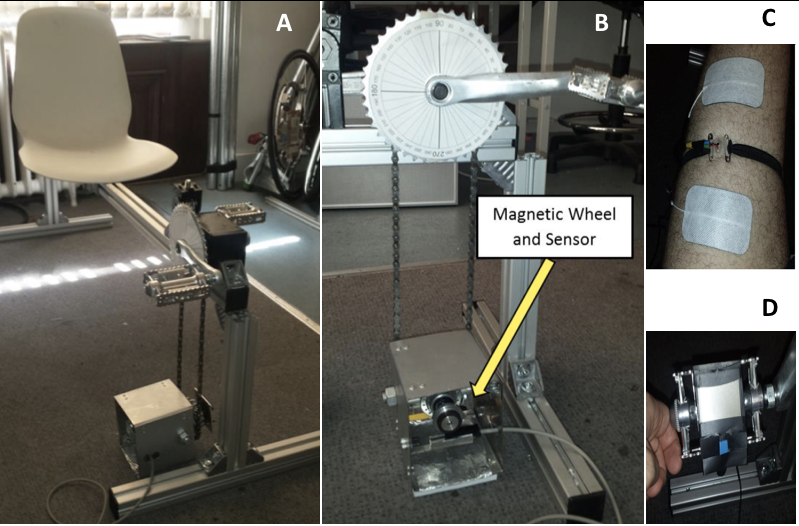
From the experimental results this method could realize FES cycling close to voluntary tracking . Figure 1. [A] Recumbent bicycle rig and [B] the crank angle encoder box with the magnetic wheel and sensor mounted. [C] Arrangement of FES electrodes (white pads) and MMG probe (transparent plastic held by black elastic band) and the Velcro strapping attachment of a force sensitive resistor. [D] Pedal sensors.
The primary focus of our work was to achieve closed- loop “on the fly” optimization for an FES system using pedal force and MMG sensors, giving the pilot control over the speed of cycling. The system must be able to make changes in the stimulation parameters based on feedback, until the desired speed has been reached, and then to maintain it. A recumbent cycling rig was constructed. This rig consisted of a frame on to which a seat was mounted. The seat could be moved forward and backwards, and a pedal crank was positioned at the front of the frame onto which two pedals were mounted. An off-axis crank box was connected to the pedal crank via a bicycle chain which enabled the two cranks to rotate together and featured a magnetic sensor that could detect movement in the crank. This rig and crank box setup can be seen in Fig. 1 and was used as a testing platform for the developed closed-loop system.
Ii. Methods
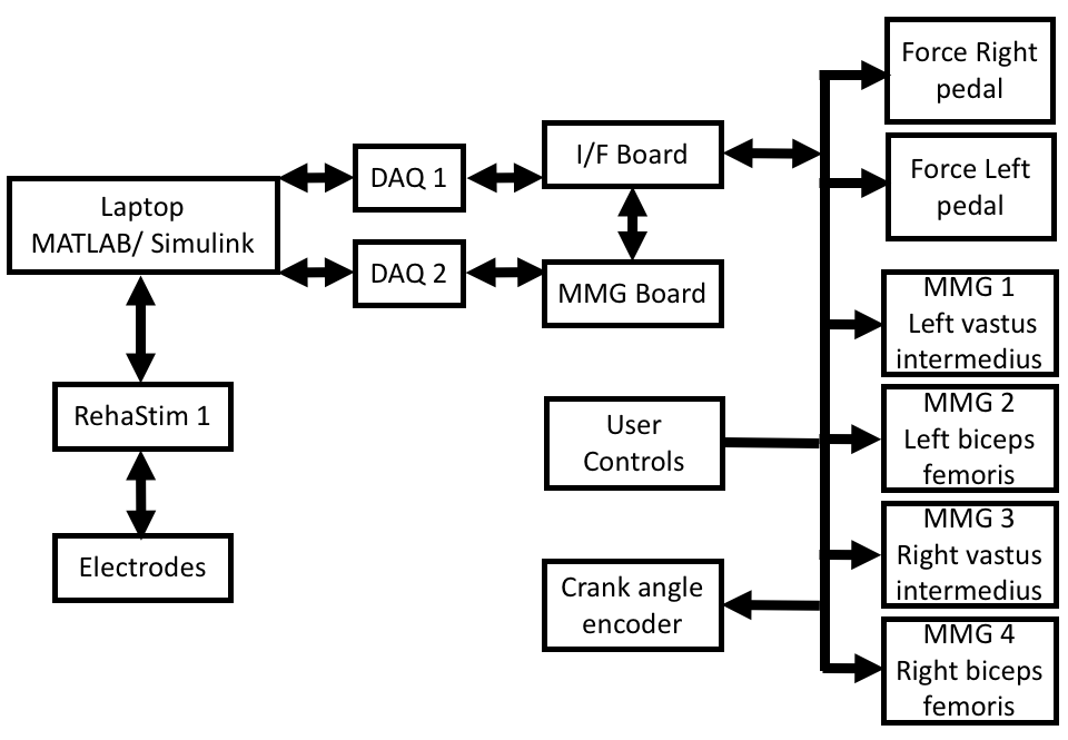
A. Overview of the proposed closed-loop FES system A schematic layout of the closed-loop FES cycling system with all the proposed design elements can be seen in Fig. 2.
USB-6009 Digital Acquisition Devices - DAQs (National Instruments, Berkshire, UK) were required to incorporate 2 pedal force sensors and 4 MMG probes. The interface board (I/F) and mechanomyography (MMG) board were created to house all the components necessary for signal processing.
The FES electrodes placement is as follows; two are placed on the quadriceps femoris, two on the hamstrings (one below the gluteal fold) and two on the gluteal maximus.
The electrodes are placed so that as much of the muscle tissue is stimulated as possible. The MMG probes are placed central between the FES electrodes for each muscle group.
The MMG probes were not used for the gluteal muscles as there was a danger that they could injure the skin due to the pressure on the seat.
Previous studies have shown that for FES cycling the quadriceps and hamstrings produce the most the power. The gluteal muscles were included in this study because stimulation of this area has been shown to reduce the possibility of pressure sores in SCI patients.
Figure 2. Schematic layout of the key elements of the proposed FES cycling system.
B. Development Of The Electronics
The electronics used in the FES cycling system were designed as an interface between data collected from the sensing elements and the data acquisition devices.
A novel design for the implementation of an ultra-low-
Cost Mmg Sensor Was Presented By . This Design
utilized a low-cost condenser microphone that could detect lateral oscillations in the muscle fibers during contractions.
This Design Was Developed Further. Two Of These
microphone transducers were housed in a specially designed chamber, one faces the muscle, and the other is used to detect background noise. One microphone will be placed in the center of the housing and detect the muscle contractions while the other is placed on the outside to detect acoustic background noise. By utilizing the two microphones together a noise cancellation effect can be achieved. The system is waterproof to reduce the risk of electrical contact with the skin during use. To provide the amplification for the output signal of the microphone an AD623 (Analog Devices, Massachusetts, USA) instrumentation amplifier is used.
Each MMG probe requires two transducers and therefore two analogue inputs; each DAQ can, thus, process inputs from 4 of these constructed probes.
Two identical sensors were required to measure the forces applied by the left and right legs onto the respective pedals
During
cycling.
(Interlink
Electronics, California, USA) were chosen for this application. A simple bridge circuit otherwise known as a voltage divider was designed to convert forces applied on to the FSR into a voltage that could be read by the DAQ.
A user control was initially designed to allow the system to be switched on and off and control how much current would be applied to the muscles, this was achieved using a rocker switch and a potentiometer. This same control was also used for the closed loop control, the potentiometer was used to allow the user to control the desired output of the system or set-point (speed, RPM). Cycling is conducted through a full 360-degree motion, and the muscle groups used: quadriceps, hamstrings and gluteals, would only be stimulated through parts of that full revolution. To determine these angles the muscle groups had to be stimulated whilst observing the efficiency of the cycling motion. However, this method was cumbersome and time-consuming. A logic circuit was designed to adjust the stimulation current (mA) at the computer, for this stage of the experiment. Once these stimulation angles were found the same control interface could be used to switch the system on and off but also control the desired speed (RPM). The muscle stimulation strategy was to stimulate the muscle groups (quadriceps, hamstrings and gluteals) in accordance with the angles found during testing.
For the Incremental Encoder Interface, a magnetic sensor- MDFK 08 was used (Baumer Electric, Frauenfeld, CH). The outputs from the sensor are digital and the rising and falling edges of the square wave can be counted to calculate the change in angle. The pulse that indicates the zero position of the wheel was critical for use a crank angle measurement
Device. The Sn74121 Was Used In A Monostable
multivibrator circuit to increase the pulse width of the zero signal, making it easier to detect.
C. Development Of The Simulink Control Model
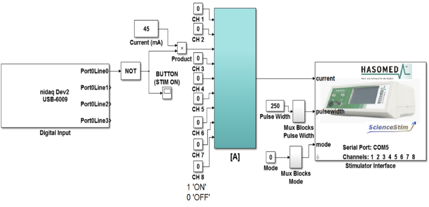
Simulink was chosen to develop the embedded control system (Fig. 3). Simulink can be used to visually model a mathematical system using ‘blocks’ of code and an initial interface block for Simulink was provided with the RehaStim on their Science Stim website . This interface block was designed to communicate with the RehaStim (Hasomed, Magdeburg, Germany) in binary code via a virtual COM port.
Figure 3. Simulink model that uses the digital input from the push button to control when FES stimulation is applied.
• Rehastim 1 – Science Mode
Simulink has many standard code blocks that can be used to construct models. One such block was the multiplexer (Mux) block. This block takes several single inputs and converts them into one vector output. By using Mux blocks and constant input blocks it was possible to create a basic working model for the stimulator. This model successfully produced output at the electrodes which were connect to the ReahStim. The next step at this stage was to improve this model so that the parameters could be externally influenced
During A Simulation. Product Blocks Were Used In
conjunction to the current input, which allow the values to be multiplied together. With these additional blocks in place it was possible to add user interface controls to the model.
Toggle switches were added to the constant values attached to the input currents of each individual channel. Variable dials were attached to values associated with the stimulation current (mA), pulse width (!s) so that these could be changed during stimulation.
• Designing The Closed-Loop Algorithm
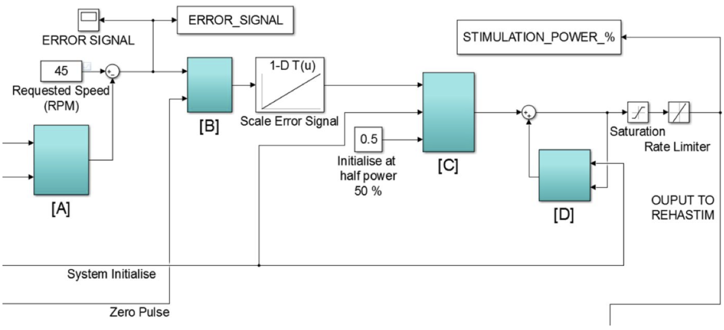
To realize a system where the muscles would receive stimulation based on the crank angle a model had to be developed (Fig. 4). This model would take an input number that represented the current angle in degrees and would then switch the FES channels on or off based on the angles found during testing. By connecting all these elements, it was possible control the stimulation applied to the muscles based solely on the calculated angle of the crank. The next step in development was to integrate the user input. The rocker switch was used to provide the user a way of starting and stopping the stimulation.
Simulink had a PID control block in its library but this had a hybrid sampling frequency set up which was unusable with the data acquisition devices, which is why standard blocks were used to recreate the same effect.
Figure 4. Schematic layout for the closed-loop algorithm. Block [A] Takes input from the cycling rig to determine the current cycling speed. Block [B] Will take the difference in the requested speed by the user and compare it with the actual speed. A zero pulse will reset this calculation each time.
Block [C] processes the logic behind how much stimulation is required at each muscle, and block [D] smoothes the output to avoid any sharp changes in stimulation. The system took several zero pulses before the angle measurement became accurate, so to avoid incorrect muscle contractions the system would not apply stimulation until an average had been found.
D. Evaluating the performance of the crank angle encoder During initial testing with the Simulink models, it was observed that the number of pulses seen during rotations of the crank were not consistent. For the first stage of the evaluation, data was collected during simulation using the crank angle encoder model, with no stimulation to the muscles. The second part of the crank angle encoder evaluation involved investigating the system performance with active stimulation. Like the collection of data obtained from the previous section, except this time all pedaling motion is coming from the FES stimulated muscles. Three crank angle encoder models were created, one which takes
Related Journal Articles & DOI Links
Selected peer-reviewed publications relevant to 12 Lead ECG Acquisition. Click the DOI to access the full paper (may require institutional access).
-
1. Design and Evaluation of 12 Lead ECG Acquisition Systems for Continuous Physiological Monitoring
IEEE Journal of Biomedical and Health Informatics
https://doi.org/10.1109/JBHI.2020.2981234 -
2. Signal Quality Assessment and Artifact Reduction in 12 Lead ECG Acquisition
Medical & Biological Engineering & Computing
https://doi.org/10.1007/s11517-020-02145-6 -
3. Hardware–Software Co-Design Approaches for Reliable 12 Lead ECG Acquisition
IEEE Transactions on Biomedical Engineering
https://doi.org/10.1109/TBME.2019.2895762 -
4. Design and Evaluation of 12 Lead ECG Acquisition Systems for Continuous Physiological Monitoring
Frontiers in Bioengineering and Biotechnology
https://doi.org/10.3389/fbioe.2020.00123 -
5. Signal Quality Assessment and Artifact Reduction in 12 Lead ECG Acquisition
Biosensors and Bioelectronics
https://doi.org/10.1016/j.bios.2021.112345 -
6. Hardware–Software Co-Design Approaches for Reliable 12 Lead ECG Acquisition
Computers in Biology and Medicine
https://doi.org/10.1016/j.compbiomed.2021.104567 -
7. Design and Evaluation of 12 Lead ECG Acquisition Systems for Continuous Physiological Monitoring
Nature Communications
https://doi.org/10.1038/s41467-020-12345-6
Why Choose Us?
Bangalore guidance for robotics, Spectre and autonomous systems projects.
Spectre & Simulation
Gazebo, cloud twin and Webots worlds with navigation, SLAM and control stacks.
Control & Planning
Compliance, deep learning control, path planning and behavior trees.
Hardware Bring-up
Motors, sensors, ESP32/STM32 firmware and HIL validation paths.
Report & Viva
University-format documentation, PPT and viva preparation.
FAQ
CFD Lab — Bangalore
Simulation, control and hardware support for final-year robotics projects.
Stacks
Worlds
Digital Twin
Control
Robots
Offline
Bring-up