Automatic Set-Point Adaptation
Lukas Hewing*, Marcel Menner*, Nikolaos Tachatos, Marianne Schmid Daners, Cosima du Pasquier, Thomas S. Lumpe, Kristina Shea, Andrea Carron, and Melanie N. Zeilinger Abstract— This paper considers the control design for a low- cost ventilator that is based on a manual resuscitator bag (also known as AmbuBag) to pump air into the lungs of a patient who is physically unable to breathe. First, it experimentally shows that for accurately tracking tidal volumes, the controller needs to be adapted to the individual patient and the different configurations, e.g., hardware or operation modes. Second, it proposes a set-point adaptation algorithm that uses sensor measurements of a flow meter to automatically adapt the controller to the setup at hand. Third, it experimentally shows that such an adaptive solution improves the performance of the ventilator for various setups. One objective of this paper is to increase awareness of the need for feedback control using sensor measurements in low-cost ventilator solutions in order to automatically adapt to the specific scenario.
Index Terms—COVID-19, low-cost ventilator, volume- controlled mechanical ventilation, patient-adaptive con- trol.
I. Introduction
Coronavirus disease 2019 (COVID-19) is an ongoing pan- demic, which is caused by severe acute respiratory syndrome coronavirus 2 (SARS-CoV-2). The viral spread of the disease has dramatically increased the demand for medical devices needed in hospitals to treat patients. Mechanical ventilators are one example of medical devices that are currently in short supply and that are critical for the treatment of patients suffering from COVID-19, cf. . To meet the peak venti- lator demands, a series of low-cost and modular solutions have been proposed, e.g., in , . In order to provide guidelines on their design, the Medicines and Healthcare products Regulatory Agency has introduced requirements that a low-cost ventilator solution ought to satisfy. These guidelines include hardware requirements, operation modes, and settings, as well as alarms for the malfunctioning of the ventilator.
This work was supported by ETH Zurich, financially and through lab access. * Co-first authorship.
L. Hewing, M. Menner, A. Carron, and M. N. Zeilinger are with the Institute for Dynamic Systems and Control, ETH Zurich, 8092 N. Tachatos and M. Schmid Daners are with the Product Development Group Zurich, ETH Zurich, 8092 Zurich, Switzerland (e-mail: tacha- C. du Pasquier, T. S. Lumpe, and K. Shea are with the Engineering Design and Computing Laboratory, ETH Zurich, 8092 Zurich, Switzerland (e-mail: A popular class of low-cost mechanical ventilators is a design that relies on squeezing a manual resuscitator bag (AmbuBag) with paddles to pump air into the lungs of a patient. Such a ventilator solution is mechanically flexible enough to satisfy the operational requirements but depends on an adequate control design to actuate the paddles. This paper addresses the controller design for a bag-based venti- lator building on design where we particularly focus on
Satisfying The Following Four Requirements:
i. Positive end-expiratory pressure (PEEP). The ventilator must provide a range of 5–20 mBar during expiration, adjustable in 5 mBar increments.
ii. Inspiratory:Expiratory ratio (I:E). The ventilator must provide a ratio of 1:2, and additionally could provide a range of 1:1–1:3.
iii. Breaths per minute (BPM). The ventilator must provide a respiratory rate of 10–30 BPM, adjusted in 2 BPM increments.
iv. Tidal volume. The ventilator must provide a tidal volume of 400 mL. Additionally, it should provide tidal volumes of 350 and 450 mL.
For an extensive list of all requirements, the reader is referred to . We investigate the influence of different patients and different settings on the operation of a bag-based low- cost ventilator. In particular, we show experimentally that feedforward control of the paddles may not be sufficient to achieve accurate tidal volume tracking (requirement iv.) for different operational settings (e.g., along requirements i.- iii.) or patient characteristics, due to varying compression and leakage losses. Instead, we propose to utilize feedback from a flow meter to adapt the controller to the individual patient and the specific operational settings, as well as small deviations in the mechanical set-up (bag placement, tubing, etc.).
The experiments were conducted using a mechanical lung (TestChest V2, Organis GmbH, Landquart, Switzerland) that is capable of simulating different patients and healthy per- sons. With this study, we want to emphasize the importance of a flow meter and an adaptation of the controller, regarding patient safety and alarm signals. Related ventilator designs do not mention the implementation of a flow meter or an adaptive scheme to cope with a patient’s pathophysiology, cf. , , –.
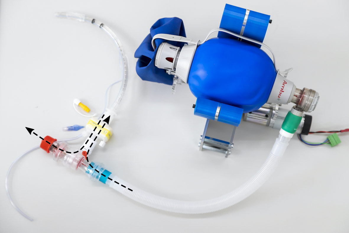
Exhale
Fig. 1. Functional prototype of the Breathe ventilator. A resuscitator bag is squeezed by two paddles, which are actuated by an electric motor.
The ventilator pushes air into the patient’s lungs, where the breath cycle is adjusted by a range of settings. Not shown: Flow sensor (placed between the patient valve and high-efficiency particulate air (HEPA) filter) and pressure sensor (attached to HEPA filter), cf. Fig. 2. (Photograph: Nicola Pitaro/ETH
A. The Breathe Ventilator
Breathe1 is a ventilator solution whose design has been adapted from . It is based on a resuscitator bag (Ambu Mark IV, Ambu, Ballerup, Denmark), which is squeezed by two paddles actuated by an electric motor, see Fig. 1.
The system is controlled with an Arduino Mega 2560. The breathing system, i.e., the airway to the patient, consists of medical-grade tubing and includes a bi-directional patient valve (included in the Ambu SPUR II Disposable Resus- citator, Ambu, Ballerup, Denmark), a passive PEEP valve (Ambu PEEP Valve, Ambu, Ballerup, Denmark) and a high- efficiency particulate air (HEPA) filter. The connection to the patient is realized by an intubation tube.
1) Actuator: The system uses a brushed 12 V DC elec- tric motor and a 1/212 gearbox (IG420504-SY5513, Con- rad Electronic, Hirschau, Germany) with a 5.5 A nominal current. The motor-driver is a full H-bridge that accepts ultrasonic PWM frequencies to regulate the motor voltage. It also embeds an analog current-sense feedback and a digital incremental encoder that are used in the motor controller.
2) Sensors: The ventilator uses two sensors: a flow meter and a pressure sensor. The flow meter (SFM3019, Sensirion, Staefa, Switzerland) is a 16-bit digital sensor able to measure an airflow between −10 and 240 standard liter per minute.
The sensor is temperature-calibrated and offers a 2% accu- racy and 1% repeatability, which makes the measurements very reliable. The tidal volume is calculated by integrating the positive airflow (from the ventilator to the lung) during one breath. The pressure sensor is a Freescale Semiconductor (MFPX5010DP, NXP Semiconductors, Eindhoven, Nether- lands), which is an analog, temperature-calibrated, and pre- amplified sensor that can measure pressures in the range between 0 to 100 mBar. The modularity of the system 1A short video of the Breathe ventilator and its functionalities can be found here: breathe.ethz.ch.
allows the sensors (flow meter and pressure sensor) to be implemented at any position of the patient’s airway. In this study, we placed the flow meter between the HEPA filter and the patient valve and connected the pressure sensor to the Luer lock port of the HEPA filter.
Remark 1 (Sensor Placement): The placement of sensors (in particular the flow sensor) is a difficult problem on its own. We placed the flow sensor to increase the accuracy of tidal volume measurements by including potential leakage of the patient valve in the measurements. For the final placement further analysis will have to be performed in extensive device testing.
3) Alarms: The implementation of alarms is a crucial component for low-cost ventilator solutions as outlined in the guidelines by the Medicines and Healthcare products
Regulatory Agency . We Use The Flow Meter And The
pressure sensor to trigger the following three alarms: (a) tidal volume (as integral of positive flow) not achieved, (b) minute volume (as one minute moving average tidal
Volume) Not Achieved,
(c) maximum inspiratory airway pressure exceeded, and
(D) Minimum Inspiratory Pressure Not Achieved,
where excess of the pressure levels in alarm (c) also stops the current breath early to prevent overpressure, and alarm (d) also serves as a disconnection alarm.
B. Control Design For The Breathe Ventilator
The basis of the control design is a reference trajectory generation for the motor position. The reference trajectory is a sawtooth signal composed of piecewise linear functions, whose slopes are adjusted based on the I:E and the BPM settings, as well as on the setting for the tidal volume. The
Bpm Is The Duration Of One Breath Cycle, I And E
define the I:E ratio, φ0 is the motor position at the beginning of the inhalation phase, and φsp is the motor position at the end of the inhalation—the set-point (sp). Throughout the paper, numeric values for the motor position are stated after gearbox reduction. The reference trajectory is tracked using a position-velocity-current cascade of proportional- integral (PI) controllers. This ensures that the I:E and the BPM requirements are satisfied. The realized tidal volume depends on correctly choosing φsp (with fixed φ0). However, for variations in patients and settings of the ventilator, φsp has to be adapted to achieve the desired tidal volume, which will be shown with an empirical study in this paper.
In order to allow for accurate tracking of the tidal volume, we propose to use a set-point adaptation, i.e., the end-point of the position reference is altered adaptively. Mathematically, we assume that the tidal volume of each breath, V (k), results
(1)
where k is a time index that refers to the kth breath cycle, φsp(k) is the motor target position of the kth breath cycle, and fθ is a bounded and strictly monotonically increasing function that relates the motor target position to the tidal volume. We denote with θ the uncertainties arising due to patient variations, hardware variations (e.g., different resusci- tator bags), or operational variations (parameter settings). An approximation of the function fθ based on geometric con- siderations is provided in Appendix A. Strict monotonicity of fθ implies that the more the bag is squeezed, the higher is the achieved tidal volume, which is a reasonable assumption and was observed to be satisfied in our experiments.
The goal of the set-point adaptation algorithm is to successively adjust the target position φsp(k) to achieve the reference tidal volume Vref, as quickly as possible but without overshoot. Hence, we want to find φref for which Vref = fθ(φref).
(2)
We propose to use a set-point adaptation that is based on integrating the difference between the reference tidal volume
(3)
where gI can be interpreted as a gain. Setting gI =
(4)
ensures that the set point, and therefore also the tidal volume, converge to the reference value monotonically, i.e.,
(6)
which is formally shown in Theorem 1 with proof in Ap- pendix B. Note that dV denotes the best Lipschitz constant or the maximum sensitivity (the steepest gradient) of the tidal volume function for all possible variations, θ, and all possible positions, φ.
Empirically, we approximate the maximum sensitivity as
∆Φ
from a grid over a set of test cases {θi} and motor target positions {φj} with step size ∆φ. Theorem 1: Consider the relation between set-point and tidal volume as in (1) with the strictly monotonically increas- ing function fθ. Using the set-point adaptation in (3) with
1
dV and dV as in (4), φsp converges monotonically and asymptotically, i.e., (5) and (6) hold. Fig. 2.
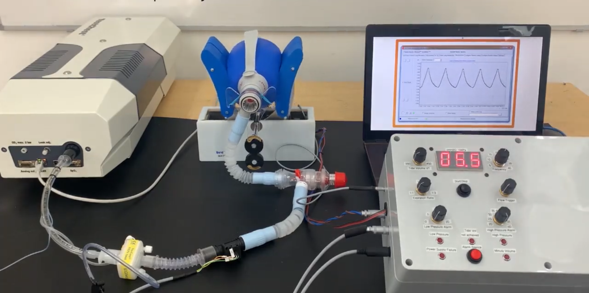
Experimental setup of the Breathe ventilator (center) with the TestChest (left) and the user interface (right). The ventilator was connected to the TestChest with standard medical components. The breathing system is constructed in the following order. A medical-grade air hose was used to connect the patient valve (including the positive endexpiratory pressure (PEEP) valve) to the resuscitator bag and another, identical air hose to connect the flow sensor and the high-efficiency particulate air (HEPA) filter in line to the PEEP valve. The pressure sensor is connected to the Luer lock port of the HEPA filter. The intubation tube was attached to the HEPA filter with an adapter. In the experiments, the inhalation path from the bag to the intubation tip had a total length of 1000 mm and a volume of approximately 195 mL. The exhalation path from the intubation tip to the PEEP valve had a length of 765 mm and a volume of approximately 120 mL.
Vl [Ml]
Fig. 3. Illustration of the basic lung mechanics, relating the lung volume (VL) to the airway pressure (paw), see . C1 is the respiratory compliance below the lower inflection point (LIP), C2 is the respiratory compliance above the upper inflection point (UIP), and Crs is the respiratory compliance between the LIP and the UIP. FRC at ZEEP denotes the functional residual capacity at zero end-expiratory pressure.
C. Experimental Setup And Protocol
For the experimental testing, the ventilator was connected to a mechanical lung, the TestChest via intubation with an inflated cuff, see Fig. 2. The TestChest is specially designed for ventilator training and has an underlying lung model integrated. The basic lung mechanics are defined by the pressure-volume curve for static conditions in Fig. 3 and the airway resistance, Raw. The respiratory compliance, Crs, is determined by the chestwall compliance, Cw, and the lung compliance, CL, as 1/Crs = 1/Cw + 1/CL.
Table I shows two sets of TestChest settings, one set modeling a healthy person and one set modeling a patient suffering from COVID-19. All physiological values were provided by and were implemented in the physiological
Related Journal Articles & DOI Links
Selected peer-reviewed publications relevant to 12 Lead ECG Acquisition. Click the DOI to access the full paper (may require institutional access).
-
1. Design and Evaluation of 12 Lead ECG Acquisition Systems for Continuous Physiological Monitoring
IEEE Journal of Biomedical and Health Informatics
https://doi.org/10.1109/JBHI.2020.2981234 -
2. Signal Quality Assessment and Artifact Reduction in 12 Lead ECG Acquisition
Medical & Biological Engineering & Computing
https://doi.org/10.1007/s11517-020-02145-6 -
3. Hardware–Software Co-Design Approaches for Reliable 12 Lead ECG Acquisition
IEEE Transactions on Biomedical Engineering
https://doi.org/10.1109/TBME.2019.2895762 -
4. Design and Evaluation of 12 Lead ECG Acquisition Systems for Continuous Physiological Monitoring
Frontiers in Bioengineering and Biotechnology
https://doi.org/10.3389/fbioe.2020.00123 -
5. Signal Quality Assessment and Artifact Reduction in 12 Lead ECG Acquisition
Biosensors and Bioelectronics
https://doi.org/10.1016/j.bios.2021.112345 -
6. Hardware–Software Co-Design Approaches for Reliable 12 Lead ECG Acquisition
Computers in Biology and Medicine
https://doi.org/10.1016/j.compbiomed.2021.104567 -
7. Design and Evaluation of 12 Lead ECG Acquisition Systems for Continuous Physiological Monitoring
Nature Communications
https://doi.org/10.1038/s41467-020-12345-6
Why Choose Us?
Bangalore guidance for robotics, Spectre and autonomous systems projects.
Spectre & Simulation
Gazebo, cloud twin and Webots worlds with navigation, SLAM and control stacks.
Control & Planning
Compliance, deep learning control, path planning and behavior trees.
Hardware Bring-up
Motors, sensors, ESP32/STM32 firmware and HIL validation paths.
Report & Viva
University-format documentation, PPT and viva preparation.
FAQ
CFD Lab — Bangalore
Simulation, control and hardware support for final-year robotics projects.
Stacks
Worlds
Digital Twin
Control
Robots
Offline
Bring-up