Cold-Tip Temperature Control of Space-borne SatelliteStirlingCryocooler:
(Currently: PhD Scholar, Electrical Engineering, SVNIT, Surat, INDIA.) (Also: Scientist/Engineer, Space Applications Centre, Indian Space Research Organisation,ISRO, Ahmedabad,INDIA (Currently:Principal Engineer, Controls & Optimization,GE Global Research Centre, JFWTC, Bangalore, INDIA) Abstract: IR (Infra-Red) detectors are widely used in Space-borne remote sensing satellites. In order to achieve a high signal to noise ratio, the IR detectors need to be operated at cryogenic temperatures. Traditionally, the cryogenic cooling of these detectors is achieved using passive cooling techniques. However recent trend is to employ Stirling- cycle based miniaturized active cryocoolers. An accurate and stringent control of active cryocooler cold-tip temperature is essential to accomplish high signal & image quality from the IR detectors. This paper presents work on investigations and comparison of performance of proposed 2-DOF (2-Degrees-of-Freedom) versus traditional 1- DOF feedback-control structures for the control of cryocooler cold-tip temperature used in IR (Infra-Red) detectors of Space Satellites. Towards this, first-principle based control oriented mathematical model simulated in Matlab/Simulink is proposed to support such investigation and controller tuning. Open-loop (system) and closed- loop (controls) simulation results are tuned & validated with the experimental data obtained from the Lab-scale test- setup of a commercial Stirlingcryocooler. The performance of 2-DOF feedback control structures are analyzed with the help of experiment results offering a better cold-tip temperature control performance.
Keywords: Cryogenic, Mathematical Modeling, 2DOF-PI, Temperature Control, Infrared detectors
1. Introduction
The Infrared (IR) detectors for space borne remote sensing applications need to operate at cryogenic temperatures since they get exposed to noise background. In the past, detector cooling was achieved using passive radiant coolers(Bard S.
1984). The limited capacity of passive coolers often limits the number of detectors and the detector power for space borne camera(Zhang et al. 2010). With the advancement of miniaturized Stirling cycle based active cryocoolers, the next generation IR remote sensing payloads employ large-area array detectors with a large power dissipation capability. The use of large area array detectors often demands stringent cold-tip temperature stability(Ross R. J. 2001) and regulation/control to a) obtain uniform temperature across IR detectors and b) maintain a uniform leakage current from all the IR detector-pixels. The stringent cold-tip temperature stability and control requirements pose a challenge to traditional cryocooler controllers, motivating to investigate and design more appropriate control structure and well-tuned well-performing controllers. There exists various advanced model based predictive multivariable and optimizing control algorithms that can be used potentially(Carlos E. G. et al.
1989)(Rafal N et al. 2015). But, on board satellite requires use of computational viable simpler PID control algorithms
And
computational time. In practice, mostly PI controllers are employed and considered sufficient for the cryocooler control electronics purpose.
Control
requirement is very stringent with permissible cold-tip temperature error being < ±0.1K. Also, the space-borne instruments employing IR detectors operates IR detectors and cryocoolers on the need basis and turns off the IR detectors and cryocoolers to conserve the Satellite power during the rest of the period. Each detector mode has got its own power requirements and in effect leads to load disturbances at the cold tip of cryocooler. For having a quick cool down and low power consumption, it is also planned to operate the cryocooler at higher cold tip temperature during non-imaging periods. Hence considering these different requirements, it is essential to have a cryocooler controller that provides a good set-point tracking as well as disturbance-rejection responses for the cryocooler cold-tip temperature. It is found that researchers have also carried outwork on dynamic simulation through mathematical modelling (Guo. D. et al. 2013)(Zhang et al. 2002) and on a scheme for stroke length control with robustness test on change of load assuming FOPDT transfer function model (Yang et al. 1999). However, detailed mathematical model with the consideration of heat and mass transfer inside the cryocooler, based on gas equation and thermodynamics is not cited. Also, detailed parametric study for load disturbance (continuous and pulsating) and change in input parameters has not been cited.
In this research work, the authors have attempted to carry out investigations by 1-DOF (degree of freedom) control structure and then by 2-DOF control-structure implemented practically for the cold-tip temperature control of acryocooler used for cooling IR detectors in space bornesatellite. Towards these investigations, first-principle energy-balance based mathematical model is proposed. The proposed mathematical model is simulated in Matlab-Simulink platform (S - function builder tool) to help controller tuning and validated with experimental results. The model is tuned using experimental data obtained from the lab-scale test setup of a commercial Stirling cryocooler (used with the Space Satellite IR detectors).
The paper is organized as follows. The section-1 presents motivation for this work with some relevant literature references. Section-2 discusses the background covering the proposed control-oriented transient mathematical model of the Stirlingcryocooler, 1-DOF & 2-DOF control structures.
Section-3 provides a brief-overview of cryocooler control-
Lab-Scale
experimental test set-up. In Section-4, simulation and experimental test-results for (a) tuning & validation of the
Performance
comparison & investigations of traditional 1-DOF versus proposed 2-DOF controller are presented and discussed. Section-5 presents the concluding remarks. Relevant references of published literature and acknowledgements are given at last.
2.1 Mathematical Modelling
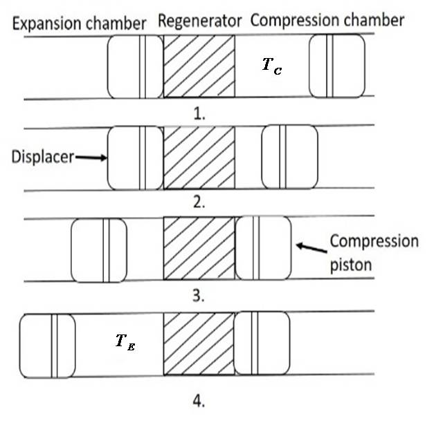
Stirling cryocooler operation is considered as per the schematic shown in Fig.1 for modelling and further
Investigations. (Randall 1985)
Fig. 1. Schematic of stirlingcryocooler Operation. Fig.1 depicts a cylinder containing two opposed piston arrangement with a regenerator in between them. It has two
T
assuming that there is no thermal conduction in the longitudinal direction. Both the pistons move without friction or leakage of the working fluid enclosed between them.
The compression piston is made to reciprocate with the help of a linear motor. Piston motion and the compression is considered as a mass spring damper system assembly (Yang
Is Mass Of Cylinder, X Is Displacement Of The
piston, D is damping co-efficient, K is friction, is length of coil, I is input current to motor, B is magnetic flux
Is The Pressure Difference Between The Two
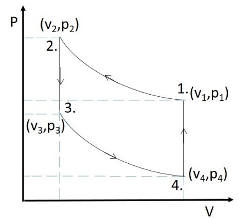
chamber. Stirlingcryocooler is governed by the ideal Stirling cycle as shown in Fig. 2 represented on P-V diagram (Thomas F.
2005)
Fig. 2. Ideal Stirling cycle- PV diagram. The ideal cycle consists of four processes as below: Process (1-2) is compression, where piston moves from the outer dead point, at that time the expansion space piston is at the inner dead point and remains stationary. The working fluid (helium) in the compression space is at ambient temperature, volume and pressure are at state (1) on the P-V diagram in Fig. 2.
In the compression space helium gas is compressed so the pressure and temperature increases as the volume decreases. The heat generated is rejected to the sink at rate (
Is The Rate Of Change Of Work Done On The System,
R is gas constant, n number of mole of gas and the changes in the volume and pressure will lead to state (2) on P-V diagram.
According to first law of thermodynamics, change in the internal energy (heating) equal to work done and in addition heat rejection(Incropera F. P 1990).
J Kg K Is Specific
heat of helium gas assumed to be constant with change in
T Is The Temperature Of The Working Fluid
(helium) in the compression chamber whose change leads to
Is The Rate Of
heat released to the sink. Process (2-3) is a constant volume heat transfer process where both pistons move simultaneously. Working fluid
To The Regenerator Matrix (Sercan
2011). Passing through matrix at constant volume causes decreases in pressure.
.
Is The Mass Of Regenerator Material,Is The
effectiveness of the regenerator which can be obtained by (e- NTU) number of transfer unit method (C. J. Paul et al. 2015) (Urieli I et al. 1984).
Are The
temperatures of regenerator before and after the Process(2-3) respectively.
Is The Specific Heat Of Regenerator
material. During process (3-4) expansion takes place as the expansion chamber piston moves away from the regenerator providing useful refrigeration of the cycle (cooling). So here at the cold tip in the expansion chamber where the effective cooling is
Is Added At This Juncture
from an external heat source (load) to the working fluid
Is The Rate At Which Heat Is
added from the base load (surrounding) which is at ambient
Tab
. Process (4-1) is again a constant volume heat exchange but
Qc
consumed in process (2-3) again to working fluid (helium) such that volume, pressure and temperature of the system returns to the state (1) shown in Fig. 2.
.
2.2 Traditional 1-Dof Controller
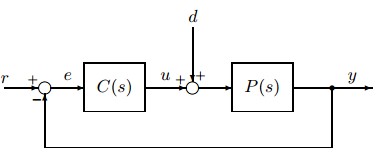
Fig. 3 shows a conventional one degree of freedom controller (1DOF). In general, such 1-DOF PI controller is implemented using a classical PI controller for the cryocooler temperature control.
Fig. 3. Conventional 1-Dof Feedback Controller
However, such 1-DOF structure poses a challenge in
Tight
temperature control), high performance for set-point tracking and disturbance-rejection simultaneously (M. Araki et al. 2003). As first attempt in the present work the above shown conventional 1-DOF feedback controller is implemented for the cold tip temperature control to confirm the predictions of M. Araki.
Two Degree Of Freedom (2Dof) Control System Has
advantages over a 1DOF system (I. M. Horowitz 1963). The extra parameter that the 2DOF control algorithm provides is used to improve their servo-control behavior while considering the regulatory control performance and the closed-loop control system robustness. Considering these advantages of 2DOF control, a digital PI controller with 2DOF has been implemented for the cold tip temperature control of cryocooler.
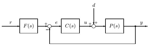
Many different equivalent forms of 2DOF exists (M. Araki et al. 2003)(V. M. Alfaro et al. 2016). The most suitable form for implementation for cryocooler control is the Set-point filter type expression of the 2DOF PID control system which is shown in Fig. 4.
Fig.4. Block Diagram of Set-point filter 2-DOF Controller The transfer function (Goodwin 2001)of the Set Point Filter and Controller for Filter type of 2DOF PID controller is
Related Journal Articles & DOI Links
Selected peer-reviewed publications relevant to 12 Lead ECG Acquisition. Click the DOI to access the full paper (may require institutional access).
-
1. Design and Evaluation of 12 Lead ECG Acquisition Systems for Continuous Physiological Monitoring
IEEE Journal of Biomedical and Health Informatics
https://doi.org/10.1109/JBHI.2020.2981234 -
2. Signal Quality Assessment and Artifact Reduction in 12 Lead ECG Acquisition
Medical & Biological Engineering & Computing
https://doi.org/10.1007/s11517-020-02145-6 -
3. Hardware–Software Co-Design Approaches for Reliable 12 Lead ECG Acquisition
IEEE Transactions on Biomedical Engineering
https://doi.org/10.1109/TBME.2019.2895762 -
4. Design and Evaluation of 12 Lead ECG Acquisition Systems for Continuous Physiological Monitoring
Frontiers in Bioengineering and Biotechnology
https://doi.org/10.3389/fbioe.2020.00123 -
5. Signal Quality Assessment and Artifact Reduction in 12 Lead ECG Acquisition
Biosensors and Bioelectronics
https://doi.org/10.1016/j.bios.2021.112345 -
6. Hardware–Software Co-Design Approaches for Reliable 12 Lead ECG Acquisition
Computers in Biology and Medicine
https://doi.org/10.1016/j.compbiomed.2021.104567 -
7. Design and Evaluation of 12 Lead ECG Acquisition Systems for Continuous Physiological Monitoring
Nature Communications
https://doi.org/10.1038/s41467-020-12345-6
Why Choose Us?
Bangalore guidance for robotics, Spectre and autonomous systems projects.
Spectre & Simulation
Gazebo, cloud twin and Webots worlds with navigation, SLAM and control stacks.
Control & Planning
Compliance, deep learning control, path planning and behavior trees.
Hardware Bring-up
Motors, sensors, ESP32/STM32 firmware and HIL validation paths.
Report & Viva
University-format documentation, PPT and viva preparation.
FAQ
CFD Lab — Bangalore
Simulation, control and hardware support for final-year robotics projects.
Stacks
Worlds
Digital Twin
Control
Robots
Offline
Bring-up