Chronic Untethered Rodent Biopotential Recording
Shreeya Sriram1*, Shitij Avlani1, Matthew P Ward2,3, and Shreyas Sen1
Abstract
Continuous multi-channel monitoring of biopotential signals is vital in understanding the body as a whole, facilitating accurate models and predictions in neural research. The current state of the art in wireless technologies for untethered biopotential recordings rely on radiative electromagnetic (EM) fields. In such transmissions, only a small fraction of this energy is received since the EM fields are widely radiated resulting in lossy inefficient systems. Using the body as a communication medium (similar to a ’wire’) allows for the containment of the energy within the body, yielding order(s) of magnitude lower loss than radiative EM communication. In this work, we introduce Animal Body Communication (ABC), which utilizes the concept of using the body as a medium into the domain of chronic animal biopotential recording. This work, for the first time, develops the theory and models for animal body communication circuitry and channel loss. Using this theoretical model, a sub-inch3, custom-designed sensor node is built using off the shelf components which is capable of sensing and transmitting biopotential signals, through the body of the rat at significantly lower powers compared to traditional wireless transmissions. In-vivo experimental analysis proves that ABC successfully transmits acquired electrocardiogram (EKG) signals through the body with correlation accuracy >99% when compared to traditional wireless communication modalities, with a 50x reduction in power consumption.

Introduction
Chronic monitoring of biopotential signals has paved the way for a better understanding of neural pathways along with improved therapeutic treatments. Recent proliferation in small form-factor wearables has enabled a new domain of continuous health monitoring. This coupled with miniaturized biological sensors, both in the wearable and the implantable domain has resulted in gathering valuable information regarding the body. Surface biopotential signals such as EKG, sEMG (Surface Electromyography), EEG (Electroencephalogram) have been studied as a means of understanding the behavior of the body.

Neural recording systems interfaced with the peripheral nervous system have been extensively explored as a method to acquire meaningful data that is used to predict and understand the motor, sensory, proprioceptive, and feedback functions of the brain. The use of animals in biological research and medicine has been a longstanding practice given the similarity between the animal and human anatomy and physiology. The current state of the art in animal signal recording includes miniaturized implantable devices with stimulation and recording capabilities. These devices implanted inside the animal body, transmit data to an external unit capable of receiving and processing this information. A vast majority of animal recording systems still rely on tethered units especially in cases when continuous long-term information is a priority. Tethered systems are not limited by the data rates and are a gold standard for reliable comprehensive information, this, however, does come with a few caveats.

Tethered systems are limited by the bias and irritation introduced by these devices on the subject. Long experimental duration is possible, however, the experimental arena is hindered by the need for long wires which in turn results in restricted movement of animals. Noisy systems result from the animals tucking and biting at the wires. Tethered systems require signal conditioning electronics to be placed external to the body, long wires also act as a site for infection and require buffers to prevent signal attenuation1. To reduce these effects, wireless telemetry of signal information is needed. Wireless recording systems have since evolved from discrete modules to system on chip devices. These small form-factor wireless devices eliminate the bias introduced by the tethered systems; however, it is limited by the high-power consumption due to the need for up-conversion of the baseband signal to higher radio frequencies2 and loss due to radiative communication. Animal studies, in particular, require the animal to wear a heavy battery pack to meet this high-power requirement. The need for constant replacement of batteries limits the experimental duration and causes undue stress on the animals which in turn corrupts the data3. On the other hand,
Ekg Electrode
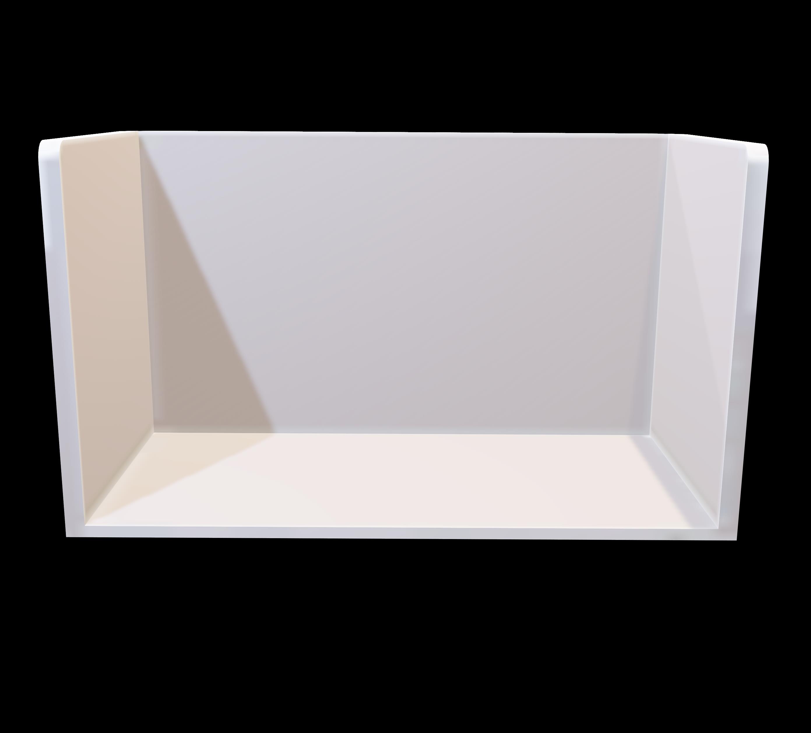
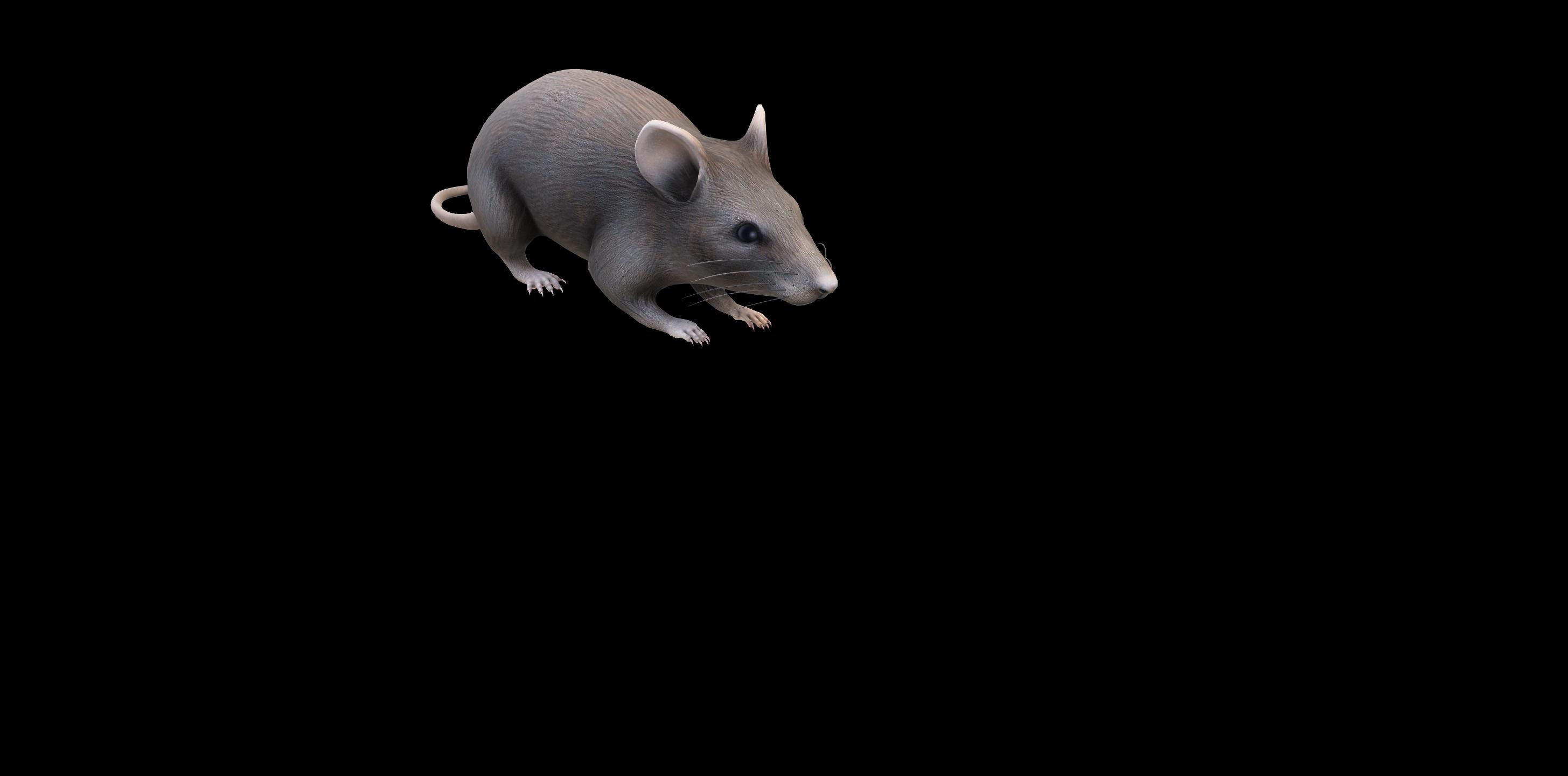
Figure 1. Animal Body Communication: a) Overview of Animal Body Communication on a Rodent Model. Custom designed sensor node is placed on the back of the rat. This sensor node is capable of sensing and transmitting the surface biopotential signals via Bluetooth and Animal Body Communication. The sensed signal is transmitted through the body to the conductive surface in the form of OOK (On-Off Keying) sequences. The specially designed rat cage is isolated from the ground surface. A conductive surface is placed on the base of the rat cage which is then connected to a Data Acquisition System (DAQ) which receives the transmitted signals. The Bluetooth receiver and DAQ are connected to a PC for processing, with the DAQ and PC ground referenced. In this model Bluetooth communication acts as a validity check for ABC. The rat model in a) was created using Paint 3D.
perpetual recording could be achieved through wireless power transfer4, however, due to the inherent high-power consumption of the sensing node with electromagnetic communication, high-power needs to be harvested, increasing the on-device harvester size significantly.
To overcome these constraints there is a need for a low power communication modality capable of withstanding the continuance of the experiment, along with having an unbiased model in which the animals are free to move in their natural environments. In this work, we introduce a novel communication modality that uses the animal body as a medium to transmit information. This system eliminates the bias introduced by the tethered systems and has a significant size, weight, area, and power benefits compared to electromagnetic communication systems. We demonstrate this Electro-Quasistatic Animal Body Communication (EQS-ABC) as a low loss, efficient channel which addresses the aforementioned drawbacks of both tethered and wireless EM communication systems. Using the body of the animal as a ‘wire’ensures signal confinement resulting in significantly lower losses when compared to traditional wireless technologies. Here, we demonstrate ABC using a rodent model and explain the theory and biophysical models of ABC, followed by ABC demonstration with a sub-inch3, custom-designed sensor node in the subsequent sections. Figure 1, describes the concept of the ABC setup, surface biopotential signals are acquired by a custom-designed sensor node that then transmits the signal using ABC through the subcutaneous tissues of the animal body using EQS-ABC. These signals are picked up by a receiver connected to the ground isolated conductive surface. In this setup, we also transmit the signals using Bluetooth as a method to compare the ABC transmitted signal with an established communication modality. In this pilot study, we use the concept of body communication and extend it into the animal domain enabling long term benefits in energy consumption along with size, weight, and area benefits. The low power requirement enables the use of smaller batteries or coils in the case of energy harvested nodes. We show the concept of ABC applied to animal biomedical studies, this modality can be extended into the neuroscience domain, with implantable nodes to acquire the signals and then communicate using the body as a medium in the future. This work presents the first validation of ABC as a communication modality. Experiments were performed with EKG signals of the rat as the chosen surface biopotential signal.

2/15
State of the Art in Wireless Biopotential Recording The first biopotential discovery dates back to 1666 when Francesco Redi measured the EMG from a specialized muscle in the electric eel5, the field of animal biopotential recordings evolved from tethered systems to wireless systems in the year 1948 when Fuller and Gordon first used radio communication for biopotential signal transmission6. Presently, multi-channel recording devices with wireless power transfer is being implemented with smart devices and arenas for in-sensor analytics. The evolution and detailed comparison of the state of the art in biopotential recording has been described in a later section.
Biopotential signals, both non-invasive (skin surface) and invasive, have been studied as a means of building bio-electronic medical devices. The central nervous system controls the body and this control can be observed by studying the changes in the peripheral physiological factors such as changes in the heart rate, muscle activity, and breathing. To study these changes, long term monitoring of these physiological signals is necessary7. EKG is one of the most widespread diagnostic tools in medicine and the similarity between human and rat EKG8 has permitted the study of various physiological conditions and cardiac diseases9,10. Along with EKG signals other surface biopotentials such as sEMG and EEG are studied in rats, analysis of these signals is used in sleep studies, epilepsy, locomotive analysis, and effect of spinal cord injuries11,12.
The study of the brain along with the body is essential in understanding the control mechanisms of the brain on physiology. Sican Liu described a novel neural interface system for simultaneous stimulation and recording of EEG/EMG and ENG (Electroneurogram) signals13. Along with surface biopotential signals, invasive recording allows for localized, high fidelity signal analysis. Neural biopotential signal analysis is a topic of extensive research in experimental neuroscience, with the aim of improving the quality of life of people with severe sensory and motor disabilities. Wireless neural recording systems have been described in insects, rodents and non-human primates. In rodents particularly, various neural interface systems which include bidirectional communication has been explored14,15. Application-specific integrated circuit (ASICs) for neuro-sensing applications has been described for implantable neurosensors4,16–18.
Chronic multi-channel neural recording is a powerful tool in studying dynamic brain function. Multi-electrode arrays permit recording of more than one channel simultaneously enabling neuroscientists to explore different regions of the brain in response to a particular stimulus. Bandwidth constraints limit the number of channels that can be recorded simultaneously resulting in a trade-off between the number of channels that can be simultaneously recorded, power requirements, and the form factor of the device. For example, Borton et al designed an implantable hermetically sealed device that was capable of sending neural signal information via a wireless data link to a receiver placed 1 meter away. This system permitted 7-hours of continuous operation17. Chae et al. describes a 128 -channel 6mW wireless neural recording IC with on the fly spike detection for one selected channel. A sequential turn-on method is used to minimize the power requirement19. Similarly, Miranda et al.
developed a 32-channel system that can be used for 33-hours continuously but requires two 1200 mAh batteries20. To achieve a meaningful experimental duration, the power consumption is often >10mW, generally dominated by the communication (radio) power. Thus, it is evident that wireless neural interfaces are power-hungry and there is a need for constant replacement of the batteries or selective channel selection in a chronic setting. To overcome these constraints wirelessly powered neural interfaces were developed, which eliminates the need for constant replacement of the batteries. Implantable devices, in particular, need wirelessly powered devices to reduce the need for a battery at the implant site. Enriched experimental arenas allow for the constant transmission of power facilitating chronic recordings. Yeager et al. developed a wireless neural interface, NeuralWISP capable of sending neural information over a 1-m range21. Lee et. al describes an EnerCage-HC2 to inductively transfer power to a 32-channel implantable neural interface4. Wireless power transfer though ensures longer experimental duration, one has to take into account the exposure to high electromagnetic fields along with concerns regarding excessive heat dissipation.

Thus, it is evident that neural recordings are limited by size constraints and overall power consumption. This leads to the next advancement in wireless biopotential recording with electro-quasistatic animal body communication.
Body Communication Basics
Body communication-based wearable technology has gained prominence over recent times as a communication modality for sending real-time information. Recent advances in using the human body as a channel for bio-physical communication has resulted in an energy-efficient information exchange modality. HBC was first proposed as a method to connect devices on a Personal Area Network (PAN) by Zimmerman et al.23, using a capacitively coupled HBC model where the return path is formed by the electrode to ground capacitance. The transmitter capacitively couples the signal into the human body which is then picked up at the receiver end. Galvanic coupling-based HBC introduced by Wegmueller et al.24, the signal is applied and received differentially by two electrodes respectively. HBC utilizes the conductivity of the human body for a low transmission loss, high-efficiency transmission modality making it ideal for energy-constrained devices. Traditional wireless body area networks (WBAN) use EM signals that radiates outside the body all around us, resulting in only a fraction of the energy being received. This radiative nature and high frequencies in WBANs are typically high energy and of the order of 10nJ/bit25. Now, if the body’s conductivity is used, it provides a low loss broadband channel that is private (the full bandwidth is available for communication). This low
Vin
Figure 2. Animal Body Communication model: a) Represents the field lines corresponding to the rat body and the transmitter ground plane. b) The rat body couples to the conductive plane and the associated capacitances are depicted. The conductive plane is ground isolated and forms the capacitance CCSG. The node consists of the ground plane which couples with the earth’s ground to form the capacitive return path. c) The circuit model associated with the experimental setup is shown in the figure.
The simplified model of the animal body communication circuit shows that the output voltage is proportional to the conductive plane to ground capacitance CCSG, return path capacitance CG_TX, and load capacitance CL. d) Simplified Human Body Communication circuit model and transfer function as depicted by S. Maity22.
loss and wide bandwidth availability along with the low-frequency operation results in ultra-low power body communication at 415 nW26 as well as very low energy communication at 6.3pJ/bit27. Low-frequency HBC was not widely adopted due to the high loss at these frequencies because of resistive (50 Ω) termination28. Recently we demonstrated, by using capacitive termination, the loss in the EQS region is reduced by a factor of >100, making it usable27,29. The first bio-physical model for EQS-HBC was developed by S.Maity22 and a detailed understanding of the forward path30 and return path31 was described.

EQS-HBC is presently the most promising low-power, low-frequency communication alternative for WBAN. It has also been shown that the EQS-HBC adheres to the set safety standards32. The state of the art in body communication has been restricted to human body communication. In this work we propose to utilize the recent developments in the concept of body communication and apply it to the animal body for biopotential and neural recordings, drastically reducing the size, weight, area, and power of the device. We propose a capacitive termination EQS communication from a sensing node on the rat’s body and also device an experimental arena to pick up these EQS signals most efficiently. This form of communication utilizes electro-quasistatic transmission through the conductive layers of the rat below the skin surface. The skin is a high impedance surface while the inner tissue layers are conductive. The transmission of the electro-quasistatic signals through the body with a capacitive return path at frequencies below 1 MHz ensures that the signal is contained within the body.
Animal Body Communication - Biophysical Theoretical Model As already established, Human Body Communication has been explored as a viable communication model, extending this to an animal body allows for a low loss, efficient channel model, compared to the traditional wireless modalities currently used. Figure 2 a and b depicts the concept of Animal Body Communication, the rat body capacitively couples with the signal
Receiver
CIRCUIT MODEL COMPONENT COMPARISON BETWEEN ANIMAL BODY COMMUNICATION AND
Human Body Communication
Figure 3. Comparison between Animal Body Communication and Human Body Communication circuit components. plane. The transmitter placed on the body of the rat modulates this electric field to transmit OOK (On-Off Keying) sequences corresponding to the sensed biopotential signal. The experimental arena is designed such that the animal moves around on a conductive surface, which is isolated from the earth’s ground. This surface picks up the EQS signals coupled onto the animal’s body and is received through ground-referenced receiver. Hence, the received voltage is inversely proportional to the capacitance of the signal plane to ground (the less the capacitance the easier it is for the wearable device on the animal to modulate the potential of the animal body and the surface). The circuit model for Animal Body Communication is described in Figure 2 c. At lower frequencies the skin impedance and the series body and foot impedance is negligible compared to the capacitance between the signal plane and ground. Given the operation of ABC in the electro-quasistatic regime, these impedances can be neglected in the computation of the channel loss. From the simplified circuit model, the output voltage Vo
(1)
In Figure 2 c and d we compare the animal body circuit model along with the established human body circuit model. The output voltage is a function of CCSG as shown in equation 1 for ABC while it a function on CBody in case of HBC. Body communication-based systems heavily depend on the body surface and ground sizes. S. Maity describes the Bio-Physical Model for HBC22, figure 3 compares the ABC model with the HBC model. Traditional HBC systems have the human body connected to a transmitter and a receiver placed on a different part of the body. The human body has a much larger surface area when compared to an animal. In this ABC setup, the sensor node is placed on the body of the rat, while the receiver is a large conductive plane. This large conductive plane ensures that the movement of the rat is not restricted, and data can be continuously recorded. In contrast, in human body communication, the body is on the earth’s ground and there exists a trunk path to ground. Due to this, the output voltage is affected by the body capacitance, unlike in the animal body setup. Figure 3 illustrates the key components of HBC and ABC. The capacitance of the body varies from ABC and HBC due to the fact that the ABC channel model consists of the additional conductive surface on which the rat is free to move. Another important component is the rat foot impedance, in ABC the rat’s feet rest on the conductive surface. CFoot and RFoot change depending on the position of the rat’s foot on the conductive plane.
In the human model, the received signal is collected from the body surface itself, thus the output voltage depends on the capacitive return path of both the transmitter and the receiver. In the ABC model, the conductive surface is ground isolated and connected to an oscilloscope which acts as the receiving unit. The transmitter couples to the floating body and the return path capacitance CG_TX from the earth’s ground plane to the transmitter ground plane completes the loop, allowing for signal
5/15
transmission. The receiver in ABC is the oscilloscope signal probe, which can be modeled as the load capacitance CL in parallel with the load resistance RL. This oscilloscope is earth ground referenced and hence eliminates the capacitive return path of HBC. The low-loss in ABC coupled with low-carrier frequency communication (as a wire) enables ABC power consumption to be much lower when compared to wireless communication modalities such as Bluetooth. This reduced power enables longer duration experiments with small form factor devices.
Results
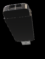
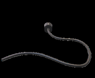
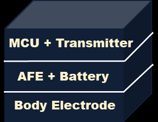
Animal Body Communication was explored as a new modality for the transmission of biopotential signals. The sensing and transmitting devices are built using off the shelf components and consist of a communication module, a processing module, a power source, and an interface to connect it to the rat body. Surface electrodes are placed on the skin surface of the rat, after employing appropriate skin preparation techniques and then connecting the electrodes to the front end of the device.
Biopotential information is sensed and modulated for transmission, simultaneously transmitting the signal over Bluetooth and through the body of the rat as Animal Body Communication. Bluetooth has long been used as a wireless communication modality and widely cited in literature as a means to transmit biopotential information. In this work, we use this gold standard of communication to compare the biopotential information received from the ABC transmitter and Bluetooth module. A correlation analysis is performed to compare both signals. Experiments were performed on a rat to prove the feasibility of Animal Body Communication.
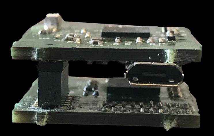
Animal Body Communication Experimental Setup
The Animal Body Communication setup is tested on Sprague Dawley rats, experiments were performed on anesthetized rats. In this study, capacitive coupling is used as a means to achieve Animal Body Communication. The details of the sensor node are described in the methods section.

Experimental Test Setup
Figure 4. Experimental Test Setup: The sensor node is placed on the rat skin surface and connected to the surface electrodes (Right Arm (RA), Left Arm (LA), and Right Leg (RL) for EKG sensing. The rat’s feet are taped on a conductive copper plate, the plate is then connected to a receiver for ABC transmission. The Bluetooth receiver and the ABC receiver are connected to the computer for signal acquisition and processing. The setup also consists of the anesthetizing unit which delivers the anesthetizing drug and oxygen to rat.

Anesthetized rats are placed on a non-conductive surface, the sensor node, in a casing, is placed on the rat skin surface and patch connectors are used to connect to the surface electrodes. The feet of the rat are placed on a conductive copper plate,
6/15
signals are acquired using the sensing unit, then transmitted via Bluetooth to a receiver connected to a computer as shown in Figure 4. Only the feet are connected to the conductive plane while leaving the body on a non-conductive surface. This depicts a case when the rat moves in a cage with only the feet on the bottom plane. ABC happens through the transmission of OOK sequences from the node through the body, to the conductive copper plate. These signals are picked up using an oscilloscope connected to the conductive plane. The oscilloscope signal probe is connected to the conductive plane while the ground probe is left floating. EKG signals are acquired using a three-electrode setup with the electrodes placed on the Right Arm (RA), Left Arm (LA), and Right Leg (RL). The RL serves as the right leg drive, common to EKG recording systems. Additional monitoring systems such as the anesthetizing setup and body vital measurement systems are present in this experimental setup not part of the communication setup. This setup aims to mimic the setup as described in Figure 1. The copper plates act as the conductive surface which in an awake recording setup will form the base on which the rat is free to move.

Time Division Multiplexing
Biopotential signal measurements require the body to be grounded to improve the CMR of the entire system. Grounding the body eliminated the floating nature which is essential for body communication. Thus, to sense and transmit biopotential signals, time-division multiplexing is used. Such multiplexing between each sensing cycle and transmission cycle ensures that surface biopotentials can be sensed accurately and also transmitted via body communication.

Post Processed Sample: Abc Decoded Ekg Signal
Post Processed Sample: Bluetooth Transmitted EKG Signal
B)
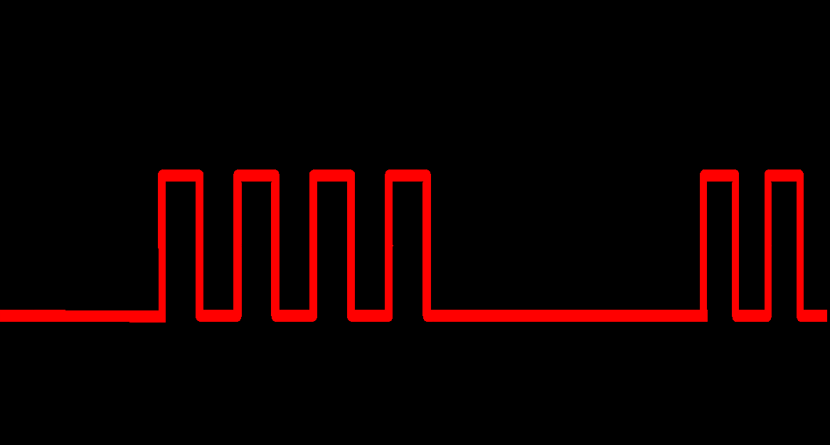
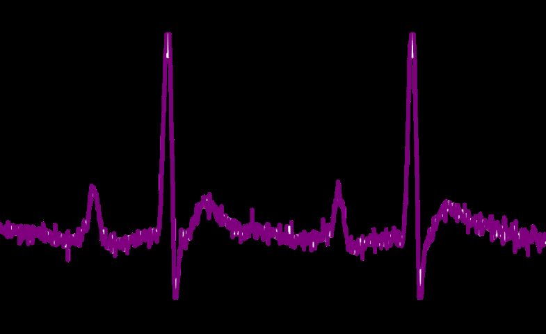
Figure 5. Time multiplexed sensing and transmission cycles: a) Sensing cycles consists of acquiring the single-lead ECG signal using three electrodes, Right Arm, Left Arm and Right Leg. ABC Transmission starts at the end of the sensing cycle and has the same duration as the sensing cycle. Bluetooth transmission duration is almost twice the ABC transmission duration.

Upon the completion of both transmissions, the sensing cycle restarts, and this cycle repeats. b) Post-processing steps on ABC transmitted sequence and Bluetooth transmitted sequence transmission In the event of simultaneous sensing and transmission, given that the transmitter is placed on the surface of the body, the sensing electrodes pick up the OOK sequences used in the transmission, resulting in a corrupted sensed signal. To avoid this, sensing and transmission are time multiplexed. This technique is critical for body communication with surface biopotentials.
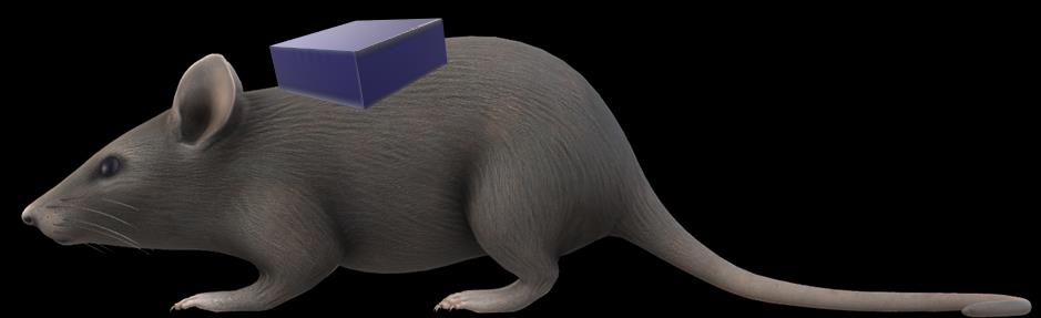
Figure 5a describes the time multiplexing cycles, data is sensed for a period of 5s followed by the transmission for 10s. The transmission of ABC and Bluetooth occurs simultaneously, however Bluetooth sequences take longer to transmit due to packet constraints resulting in a longer transmission time as compared to the sensing time. Following the transmission cycle, the sensing cycle repeats. ABC data is sent as OOK sequences which are then demodulated and decoded to retrieve the EKG sample as shown in Figure 5b. Bluetooth samples are transmitted as characters corresponding to the ADC codes, which are then converted to corresponding samples to compare with the transmitted ABC signal.

Time Domain Correlational Analysis on Acquired EKG Signal EKG signals are chosen for testing the animal body communication setup. The experiment was conducted on a total of 8 Rats over 2 months. This current set-up ensures continuous synchronized transmission of the biopotential signal from both the Bluetooth module and the ABC transmitter.

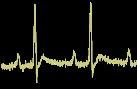
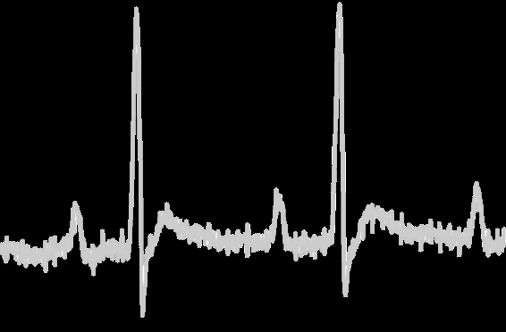
As mentioned before, the signals are time-multiplexed allowing Animal Body Communication. The EKG signal is sensed for a period of 5s followed by simultaneous transmission of ABC and Bluetooth. Figure 6 shows the EKG sample comparison, 6a shows the Bluetooth and the ABC EKG data for a period of 0.6s, these two signals are overlaid in 6b, the PQRST peaks of the characteristic EKG signal align, similarly, the data is compared for all 8 rats and correlation accuracies across each trial is
Related Journal Articles & DOI Links
Selected peer-reviewed publications relevant to 12 Lead ECG Acquisition. Click the DOI to access the full paper (may require institutional access).
-
1. Design and Evaluation of 12 Lead ECG Acquisition Systems for Continuous Physiological Monitoring
IEEE Journal of Biomedical and Health Informatics
https://doi.org/10.1109/JBHI.2020.2981234 -
2. Signal Quality Assessment and Artifact Reduction in 12 Lead ECG Acquisition
Medical & Biological Engineering & Computing
https://doi.org/10.1007/s11517-020-02145-6 -
3. Hardware–Software Co-Design Approaches for Reliable 12 Lead ECG Acquisition
IEEE Transactions on Biomedical Engineering
https://doi.org/10.1109/TBME.2019.2895762 -
4. Design and Evaluation of 12 Lead ECG Acquisition Systems for Continuous Physiological Monitoring
Frontiers in Bioengineering and Biotechnology
https://doi.org/10.3389/fbioe.2020.00123 -
5. Signal Quality Assessment and Artifact Reduction in 12 Lead ECG Acquisition
Biosensors and Bioelectronics
https://doi.org/10.1016/j.bios.2021.112345 -
6. Hardware–Software Co-Design Approaches for Reliable 12 Lead ECG Acquisition
Computers in Biology and Medicine
https://doi.org/10.1016/j.compbiomed.2021.104567 -
7. Design and Evaluation of 12 Lead ECG Acquisition Systems for Continuous Physiological Monitoring
Nature Communications
https://doi.org/10.1038/s41467-020-12345-6
Why Choose Us?
Bangalore guidance for robotics, Spectre and autonomous systems projects.
Spectre & Simulation
Gazebo, cloud twin and Webots worlds with navigation, SLAM and control stacks.
Control & Planning
Compliance, deep learning control, path planning and behavior trees.
Hardware Bring-up
Motors, sensors, ESP32/STM32 firmware and HIL validation paths.
Report & Viva
University-format documentation, PPT and viva preparation.
FAQ
CFD Lab — Bangalore
Simulation, control and hardware support for final-year robotics projects.
Stacks
Worlds
Digital Twin
Control
Robots
Offline
Bring-up