Noor Alhuda Ameen, Omid Arfaie, And Ramazan Unal
Abstract— The prosthetic socket is an essential part in ensuring comfort and stability for the overall prosthesis system. This study proposes a multi-material/thickness individualized transtibial prosthetic socket that focuses on providing comfort. This study aims to identify the proper material and thickness to protect Calf areas and reduce the pressure around bone areas. First, the socket is divided into four parts depending on the pressure- sensitive/tolerant regions. After identifying the thickness range for each concerned area, the thickness and mate- rial are selected based on the Pressure-Pain Threshold (PPT) test, and the finalized design is then prototyped. The prototyped individualized socket (i-Socket) is 22% lighter than the participant’s own socket. Results of the pilot experiments with an amputee participant showed that the pressure inside the socket decreased by 45% and 31% for the Tibia and Fibula regions, respectively. Additionally, the self-selected CoM velocity for the walking experiment is increased by 15% compared to the similar studies in the literature. Regarding the kinematic results, symmetry in the knee and ankle joints increased by 65% and 2% when using the i-Socket compared to the results with the participant’s own socket.

Index Terms— Transtibial prosthetic socket, Biomechan- ics, Pressure distribution, Additive manufacturing.
I
T is documented that the rejection or abandonment rate of prostheses is estimated to be between 24% and 70% . The reasons behind rejecting or abandoning the prostheses are discomfort while using the prostheses, the quality of the prostheses, the prosthetic appearance, and the high cost of the prosthesis . The rationale behind this is several interconnected factors, one of which is high-pressure distribu- tion, and a heavy socket that induces discomfort, instability, pain at certain places in the body, insufficient socket fitting, skin damage, patient fatigue, and weakening of the socket’s structural integrity. The socket is the interface between the user and prosthesis, where control and stability are provided from the socket to the entire prosthesis . Therefore, a good interface between the residual limb and socket is essential for a successful prosthetic fitting and rehabilitation of a transtibial amputee . Consequently, a poor socket fit disrupts this This study is funded by the Scientific and Technological Research Council of Turkey (TUBITAK) under the project number 123M351.
The authors are with the Human-Centered Design Laboratory, De- interface, reducing the amputee’s mobility. The lack of mo- bility contributes to muscle atrophy, and the physical stress of loading causes skin issues and back pain . However, a poor socket fit can increase these problems or directly trigger these impairments . Similarly, if high interface pressure between the residual limb and prosthetic socket occurs, participants will experience instability, discomfort during daily activities,
And Pain Or Skin Damage –. Moreover, Heavy Socket
contributes to several negative outcomes, mostly unease, pa- tient fatigue, and instability due to the possibility of exerting excessive stress on the suspension system . As a result of this, abandoning the prosthetic occurs, leading to decreased locomotion .
A commonly used approach for reducing pressure around the residual limb by adding extra contact and hollowed area for tolerated pressure and sensitive region, and it’s called the Patella Tendon Bearing (PTB) prosthetic socket for transtibial amputees . Moreover, a Total Surface Bearing (TSB) prosthetic socket is also used, and it evenly distributes the pressure across the residual limb by keeping the residual limb in full contact and applying gentle pressure to the Calf area.
The TSB socket shows better results than the PTB socket in terms of suspension, pressure distribution, and socket mass. However, the PTB and TSB socket masses are around 1.11 kg and 1.04 kg, respectively . Nevertheless, a participant uses PTB and TSB sockets for 1.5 years, both of which fail to relieve pressure around the sensitive region . An additional approach using reinforcement, like carbon fiber, fiberglass, and cement, on a 3D-printed Polylactic Acid (PLA) socket, enhances structural strength and reduces socket failure under load. The approach aims to improve the mechanical performance of prosthetic sockets without complicating the design . Although cement coating results in the highest strength, further research is needed to evaluate long-term strength . However, the study does not investigate comfort or pressure distribution, which limits addressing its effect on residual limb comfort and pressure mapping. Another approach uses Selective Laser Sintering (SLS) and a Finite Element Analysis (FEA) framework to build the prosthetic socket made from Duraform polyamide (PA) with localized reductions in wall thickness to evaluate structural performance.
The design is validated by comparing the deformation and failure loads, and the results show that the predicted failure loads match within 3% and the deformation at the bottom of the socket is within 25% of the FEM predictions under
2
sub-fault loads . The pressure distribution applied in the model is not patient-specific, and it is not feasible to obtain accurate values for each socket design . Nonetheless, the evaluation does not include a pressure map distribution for the socket design, which is for assessing how these changes in wall thickness affect pressure distribution. An ongoing alternative solution for a transtibial prosthetic socket involves designing a multi-material 3D-printed socket. The study aims to design comfortable and low-cost prosthetic sockets by targeting the load and off-load zones. The proposed idea is that load zones are covered with PLA material and soft material, like rubber material, that covers the off-load zones. In addition, different infills are tested to achieve a suitable balance of resistance and mass of the socket . Although the concept of surface interaction between the socket and lower limb through load and off-load is valid, time is required to confirm the materials’ safety and reliability for daily activities . Further study focuses on designing Variable Impedance Prosthetic (VIPr) sockets using computer-aided design and manufacturing using TangoBlackPlus (rigid material) and VeroWhitePlus (flexible material). Studying the depth of bones and connecting it with the Young’s modulus of the materials will help in material selection . Moreover, when the bone is far from the skin, the material is chosen to be stiff, and when the bone is close to the skin, the material should be flexible. When the participant’s speed is compared while wearing the VIPr socket and the participant’s socket, it appears that the participant’s speed increases by 16% while wearing the VIPr socket .
In addition, the mass of the VIPr is almost three times heavier than the participant’s own socket (Carbon fiber material), and this is because the socket wall is thicker to achieve struc- tural integrity and due to material properties limitations .
This study is aimed at individualizing transtibial prosthetic sockets based on designing a multi-material/thickness socket according to the participant’s PPT in sensitive areas. The PPT test is employed to determine the material and thickness of each region for improving comfort with pressure reduction around the pressure-sensitive/tolerant areas. The areas that are considered in the study are the Tibia, Fibula, and Calf areas.
Multiple wall thicknesses are selected, based on a design study conducted using existing pressure values. After this design study, a PPT test is conducted to finalize material and thickness selection for each area, depending on the participant’s test results. To ensure the socket is fitted with the participant’s residual limb, the residual limb scanning is conducted in a careful way. Also, to avoid a negative impact on stability, the prosthetic socket mass, approximately, remains the same as the participant’s own socket . A pressure map distribution for the concerned area is obtained during a static test con- ducted using a universal compression machine. The results for the specified areas show that the pressure in these areas is reduced compared to the pressure results of existing sockets in the literature. Additionally, the functional evaluations by a transtibial amputee are performed to investigate the pressure distribution inside the socket and the kinematic performance during walking at self-selected speed. The results show that the pressure and kinematic metrics are improved while using the individualized socket (i-Socket) compared to the results with the participant’s own socket (POS).
Ii. Methods
In this section of the study, the methodology for designing and identifying the thickness and material selection procedure is presented.
A. Conceptual Design
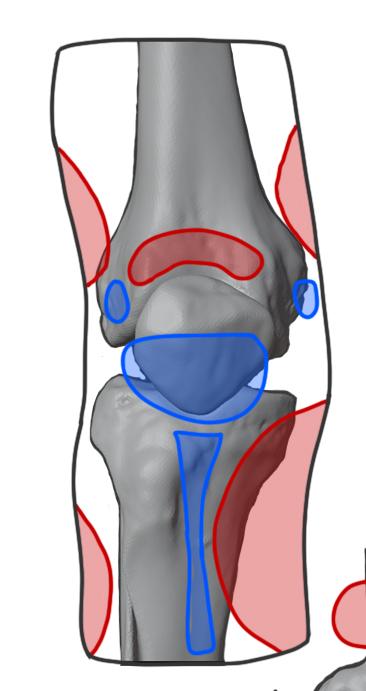
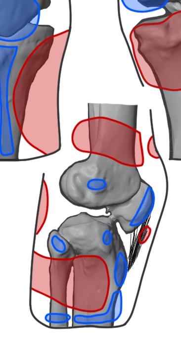
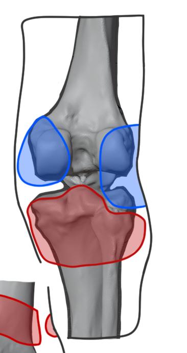
Designing a comfortable socket depends on distributing the pressure in the right areas. The areas that tolerate pressure need a rigid material to avoid high pressure, and the pressure- sensitive areas need a flexible material. To determine areas that need protection or require flexibility, a PPT test should be performed on the participant, but initially, the soft tissue and bone areas are assumed, depending on pressure-tolerant and pressure-sensitive regions, as shown in Fig.1. The upcoming subsections provide detailed information about all designs and analyses.
C)
Fig. 1: This diagram shows the pressure-tolerant and pressure- sensitive areas . Anterior view (a), Lateral view (b), Posterior view (c). Pressure-sensitive areas are highlighted in blue, and Pressure-tolerant areas are highlighted in red.
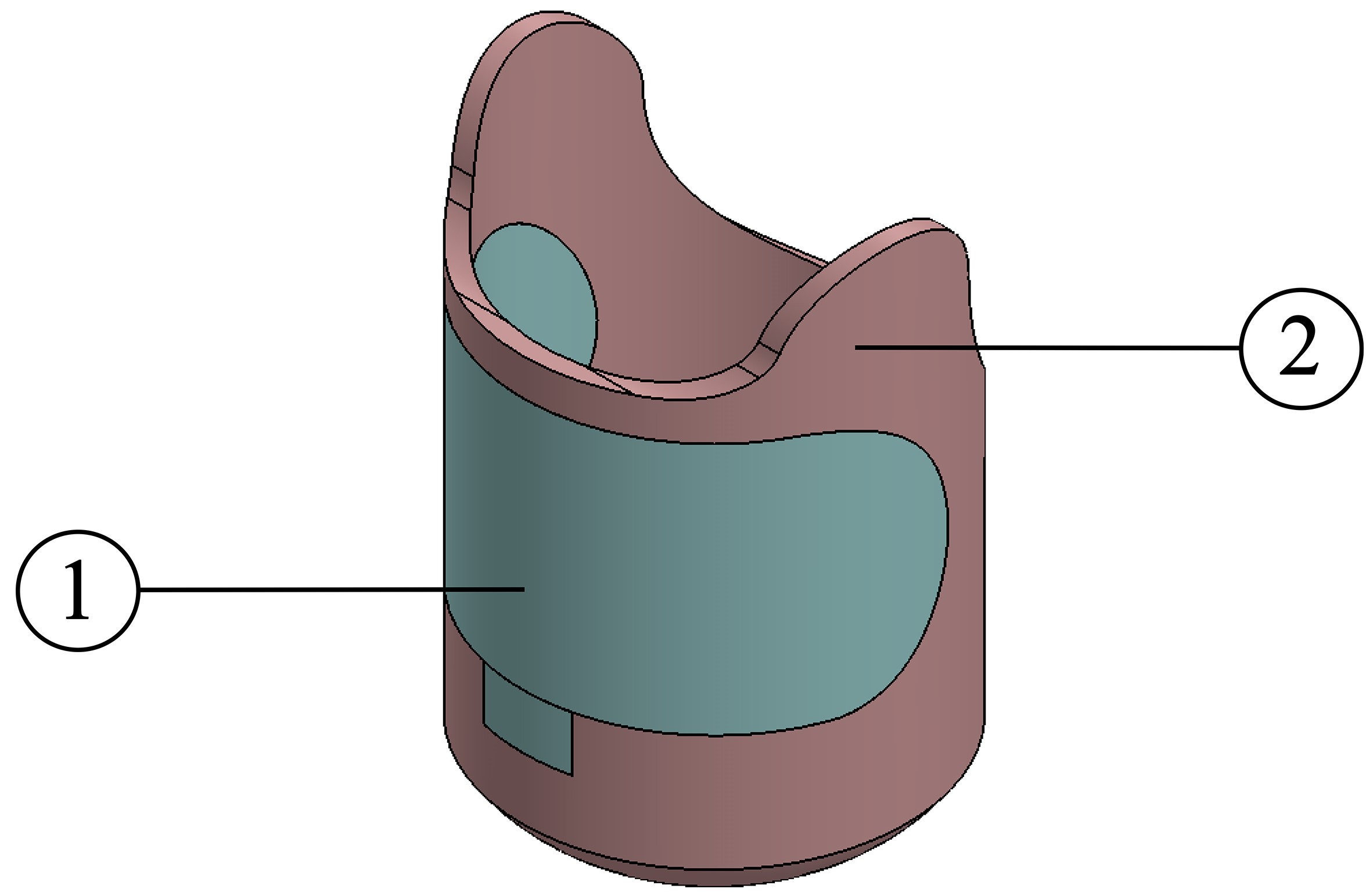
At first, hypothetical models are built to observe the stress acting on the socket during static analysis with a diameter of 0.0962 m and a height of 0.16 m. The first socket design addresses pressure-tolerant areas by using rigid materials, with carbon fiber and Kevlar to be evaluated. Pressure- sensitive areas are accommodated through the placement of a soft and flexible material, and in this design, Thermoplastic Polyurethane (TPU) material is considered. The material ar- rangement for Design 1 is presented in Fig. 2a. As an initial assumption before determining the thickness, the thickness of Design 1 is considered to be 5 mm.
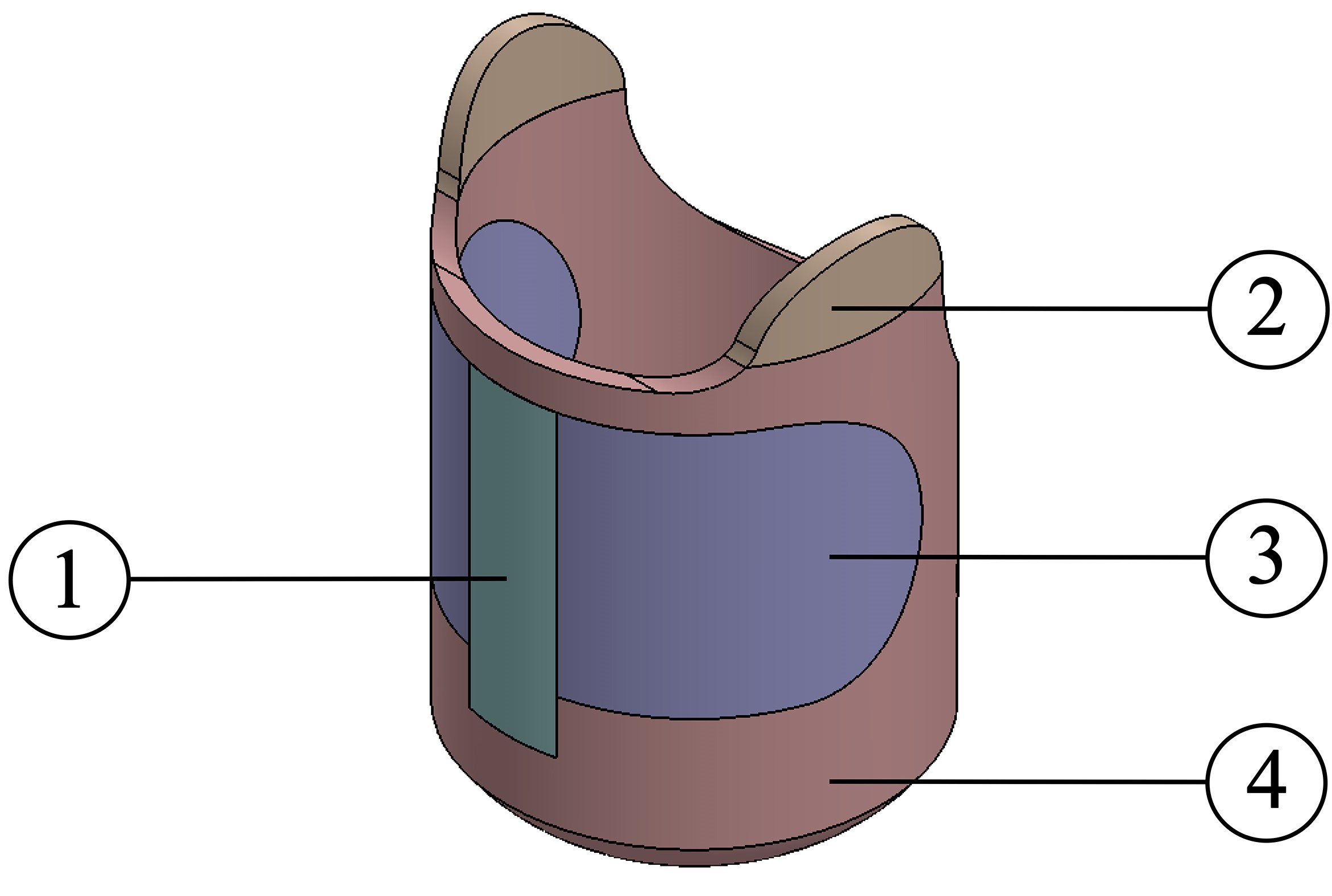
Design 2 is divided into four sections, as shown in Fig.2b. The socket contains four materials, with Kevlar and Carbon fibers used for pressure-tolerant areas, and PLA and TPU for pressure-sensitive areas. Furthermore, as in design 1, all areas have the same thickness of 5 mm.
AMEEN et al.:DESIGN AND EVALUATION OF A MULTI-MATERIAL AND MULTI-THICKNESS PROSTHETIC SOCKETS
(B)
Fig. 2: CAD model of Design 1 (a): Pressure-sensitive areas (1) and pressure-tolerant areas (2). CAD model of Design 2 (b): Pressure-sensitive areas (1&3) and pressure-tolerant areas (2&4).

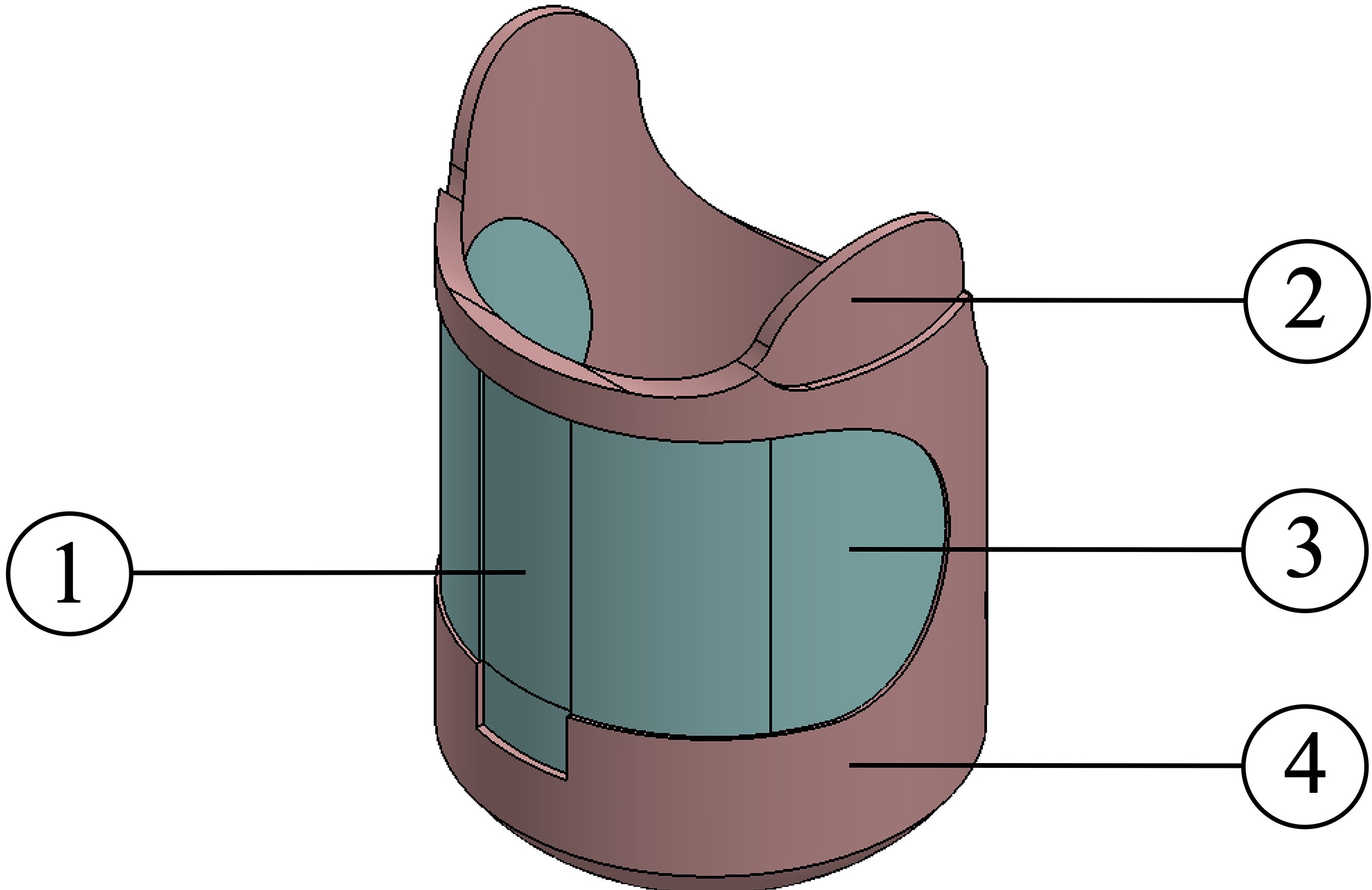
For achieving a high material rigidity or flexibility, the thickness of each area can be changed according to the output needed, and in addition, changing the thickness helps in reduc- ing the socket’s overall mass. Design 3 integrates the material layout distribution of design 2 with the material selection of design 1, but modulating the thickness of each region to achieve the desired rigidity and flexibility, as illustrated in Fig.3. The thicknesses are initially assumed, with pressure- tolerant areas at 5.00 and 3.00 mm, and are tested with both Carbon fiber and Kevlar, while pressure-sensitive areas have thicknesses of 4.00 and 3.00 mm, manufactured from TPU.
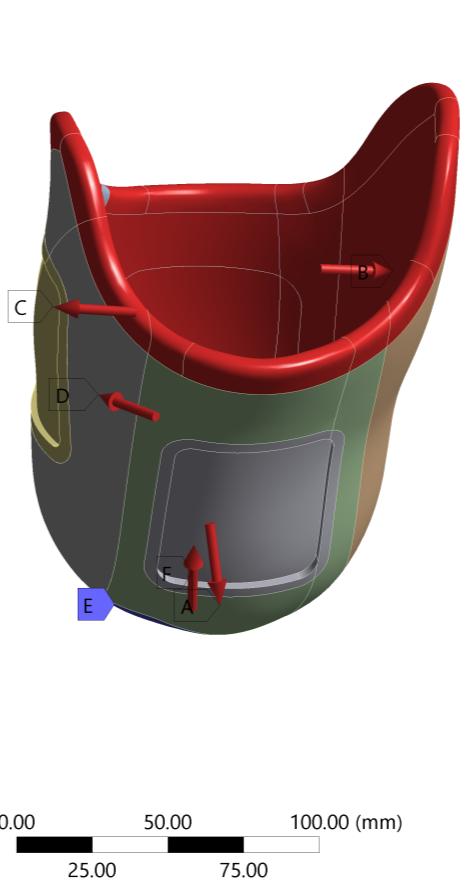
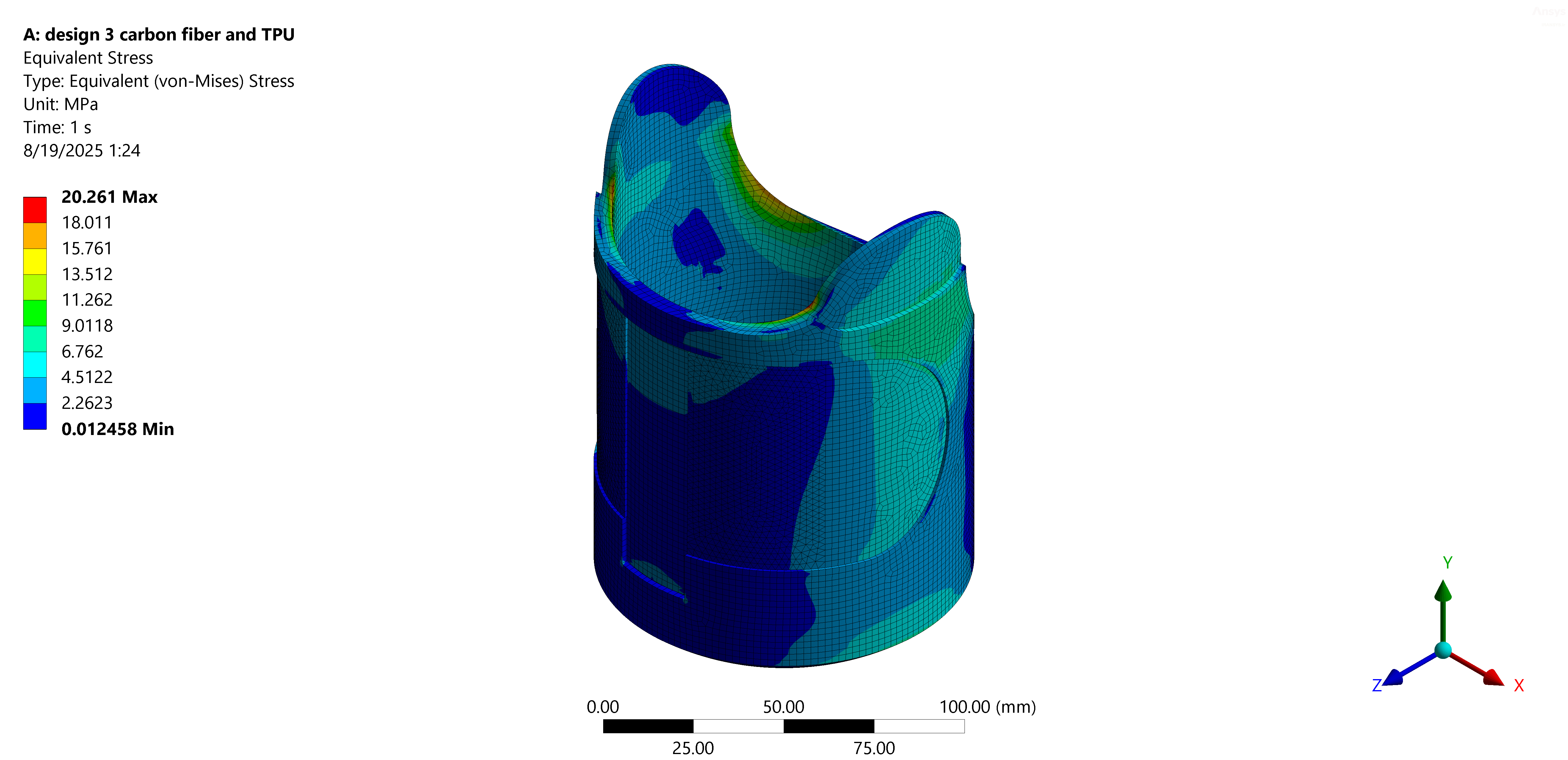
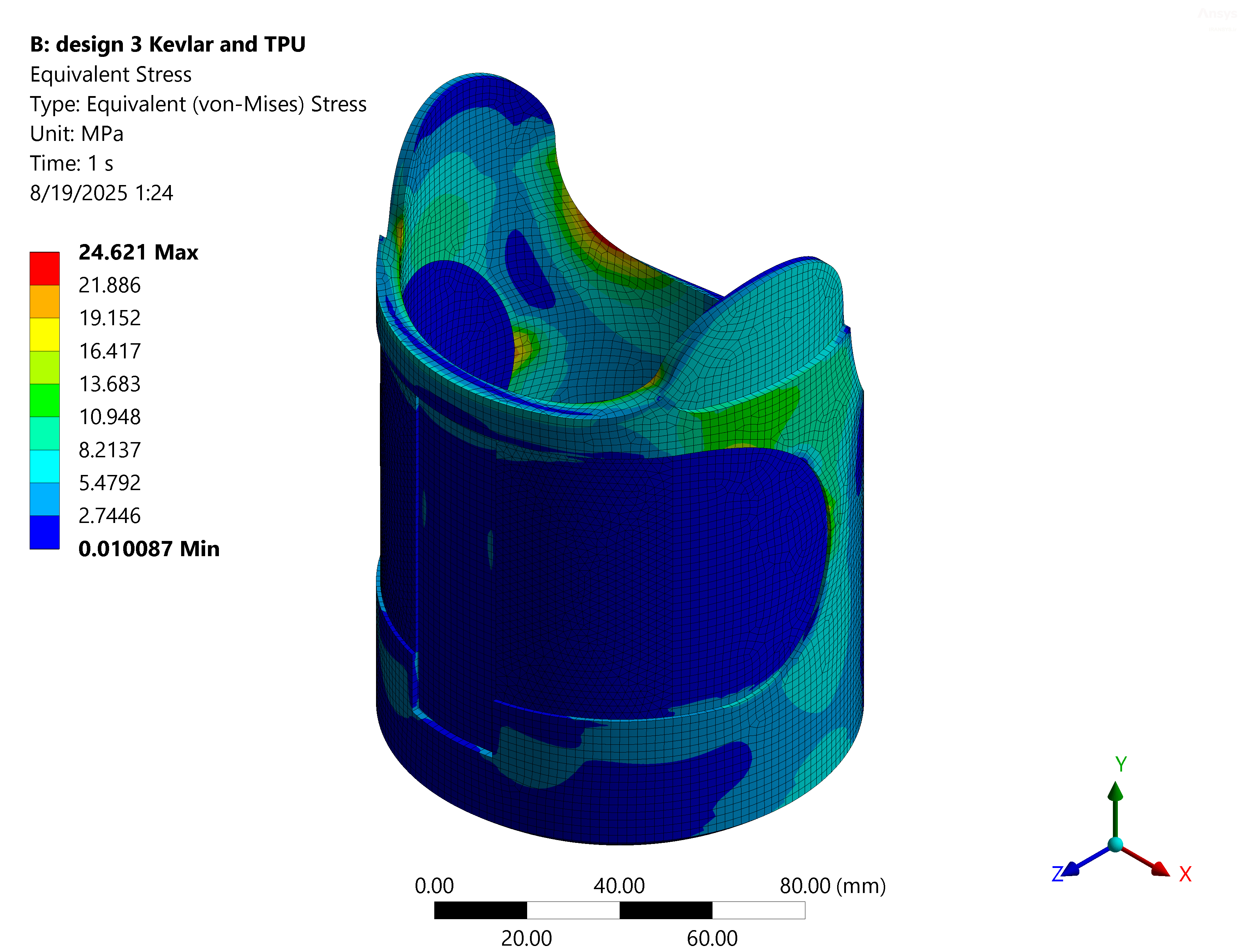
Fig. 3: CAD model of Design 3: Pressure-sensitive areas (1 & 3), and Pressure-tolerant areas (2 & 4). For all designs, a stress analysis is conducted according to the forces and pressures acting between the socket and residual limb during the stand phase , . The stress analysis for design 3 provides critical insight from material and design perspectives. According to the results and from a material perspective, carbon fiber transmits stress to adjacent regions, while Kevlar reduces stress in medium and flexible areas, as presented in Fig.4.
B)
Fig. 4: Design 3 structural analysis, a) Stress analysis using Carbon fiber for pressure-tolerant areas, b) Stress analysis using Kevlar for pressure-tolerant areas.
Additionally, from the design perspective, different thick- nesses don’t necessarily decrease maximum stress; they help redistribute stress across regions and control rigidity and flexibility. Based on stress analysis, design 3 reduces localized peaks in sensitive areas compared to designs 1 and 2, and with multiple thicknesses, stress is distributed evenly across the socket. To address all the study’s requirements, design 3 is considered the final design due to its ability to redistribute stress and control rigidity and flexibility.
B. Thickness Range Determination
To specify the range of thicknesses for the areas concerned in the final design, which satisfies the study’s requirements, parametric research is conducted based on the PPT of healthy and amputee participants in the literature. Since amputee PPT test data are not provided for all regions, healthy subjects’ PPT test values are used for the thickness range determination of the Tibia region.
To identify the thickness in the Calf area, the PPT value of 0.438 MPa with a sensor area of 100 mm2 is considered as the constraint for this region . Using a parametric analysis, the desired thickness for this area is identified. The inner pressure in this area is considered as the standing load on the socket, approximately equal to 0.100 MPa . For the Calf area, three thicknesses are considered as 5.00 mm, 7.50 mm, and 10.00 mm. For thicknesses below 5.00 mm, the analysis fails, and a thickness of more than 10.00 mm will increase the socket’s mass. The study results are presented in Table I. The results show that thicknesses of 7.50 mm and 10.00 mm do not exceed the constraint, and the pressure values are almost identical for these two thicknesses. Hence, to achieve a low- weight prosthetic socket, a thickness of 7.50 mm is considered.
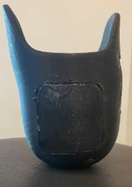
TABLE I: The results of the pressure on the Calf area for
0.373
For the Fibula area of the residual limb, the PPT test value is reported as 0.490 MPa , but the utilized sensor area around this region is not specified. Based on the findings in the literature , the applied pressure on the Fibula area during standing is reported as 0.03 MPa. Since the Fibula region is considered a pressure-sensitive area, to achieve both strength and lightness in the socket, the selected thickness for the parametric study for this area is considered to be between 3.00 mm and 6.00 mm. According to the results presented in Table II, all thicknesses are considered in the range since none of the thicknesses exceed the stress constraint.
4
TABLE II: Four considered thicknesses in the parametric study
0.237
The contact pressure around the Tibia area is nearly 0.01 MPa during the standing task . Accordingly, to identify the thickness in this region, the PPT test value of the Tibia region for healthy participants is reported as 0.454 MPa, and the sensor contact area is 100 mm . The thickness range considered in this study is from 3.00 mm to 6.00 mm, as shown in Table III, which includes all the thicknesses in the range from the parametric study of the Fibula area.
TABLE III: Four considered thicknesses in the parametric study
0.096
Based on the study results, 5.00 mm and 6.00 mm thickness results are similar, as presented in Table I and Table II. Due to this, 5.50 mm is included in the range. The final thickness ranges for the PPT test are considered to be 3.00 mm, 4.00 mm, 5.50 mm, and 7.50 mm.
C. Ppt Experiments
Four different materials with various thicknesses are tested in the PPT test to finalize the participant’s socket materials and thicknesses for the concerned areas. To build upon these principles, the following discussion is a review of existing PPT test methods for healthy and transtibial participants. An existing study uses a pneumatic tourniquet connected to the computer-controlled air compressor, which is wrapped around the area to be tested . In addition, the compressor is con- nected to the electro-pneumatic converter for converting the voltage into proportional output pressure, controlled via a data acquisition card. A software program is written in LabVIEW 5 for pressure control. The pain intensity is recorded using an electronic VAS. The compression cycles are carried out at 5-minute intervals, and the compression rate is set to 1.2 kPa/s. Another cycle has three compression rates: 0.25, 0.5, and 0.1 kPa/s. Another approach presented in the literature, a comparison for measuring PPT is conducted between two spring-loaded PTM (100-1000 kPa and 200-2000 kPa) and a pressure pain algometer (20-2000 kPa) . Three regions are tested, including nail bed (thumb/ big toe), bone (Processus styloideus, medial malleolus), and muscle (Thenar eminence, abductor hallucis). The two PTM devices show close results, while the algometer’s pressure results for the nail bed and bone region are less . The following study measures the PPT for 11 areas on the residual limb by applying pressure to the skin through a circular material connected to a load cell . For the participant, a 15-minute rest with the knee extended is applied before the test, and a 10-minute rest is provided between tests. The materials used in this test are pelite (mainly used for liners) and polypropylene (used for manufacturing prosthetic sockets). The load rate is controlled manually at 4 N/s and a maximum force of 200 N .
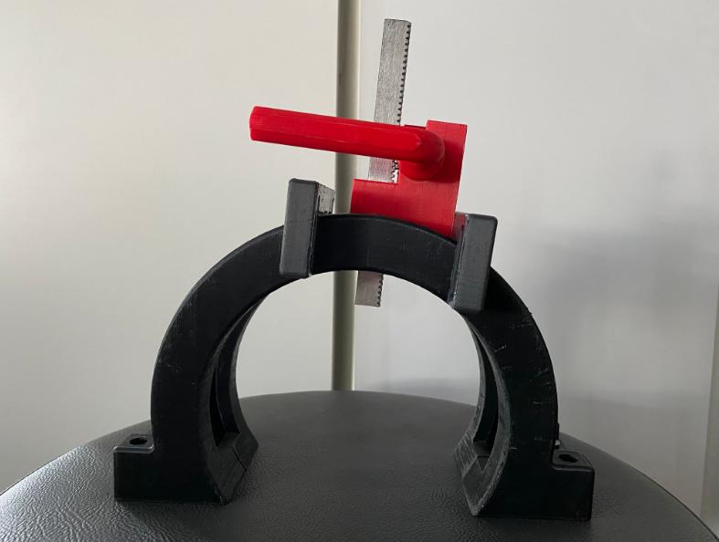
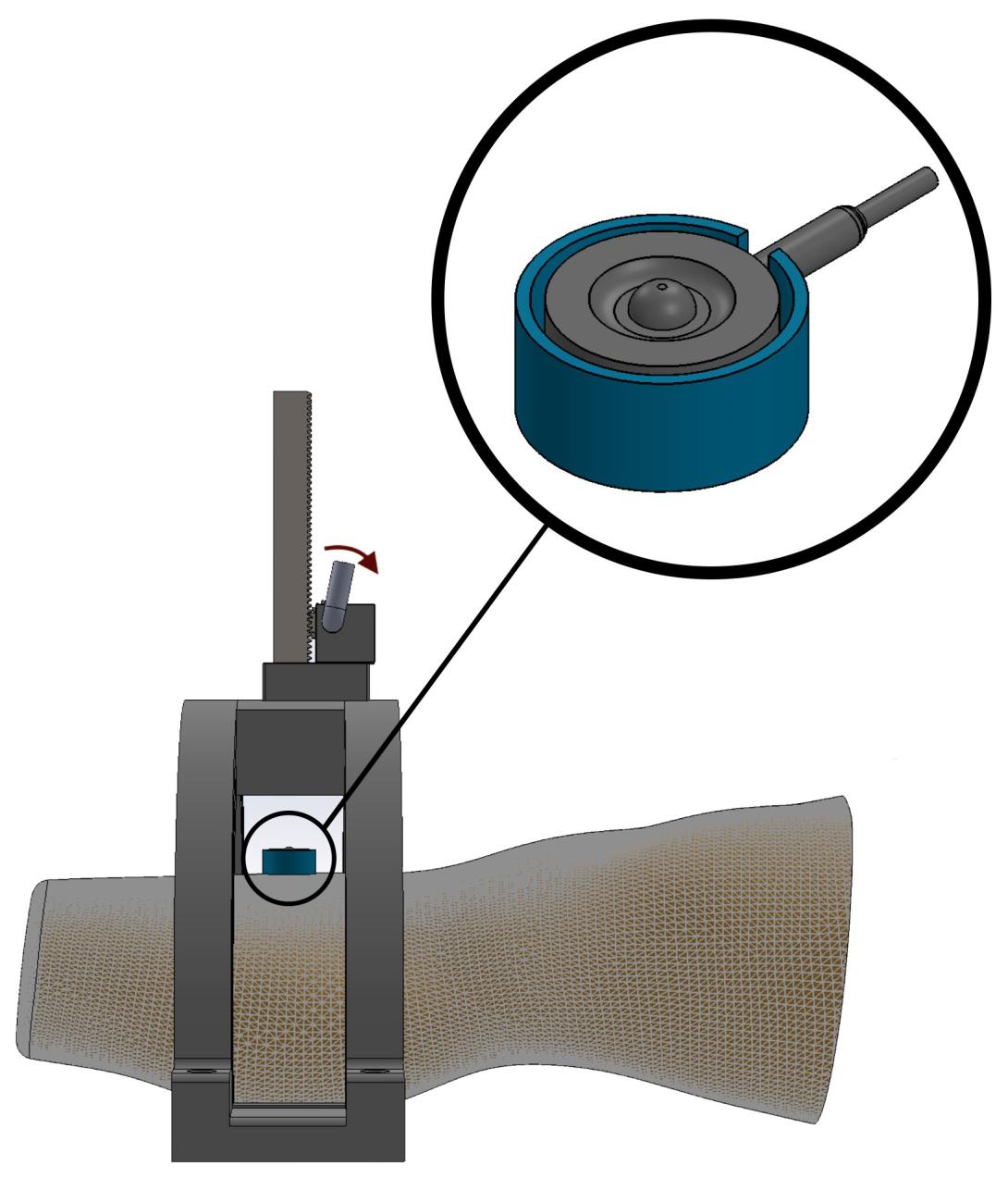
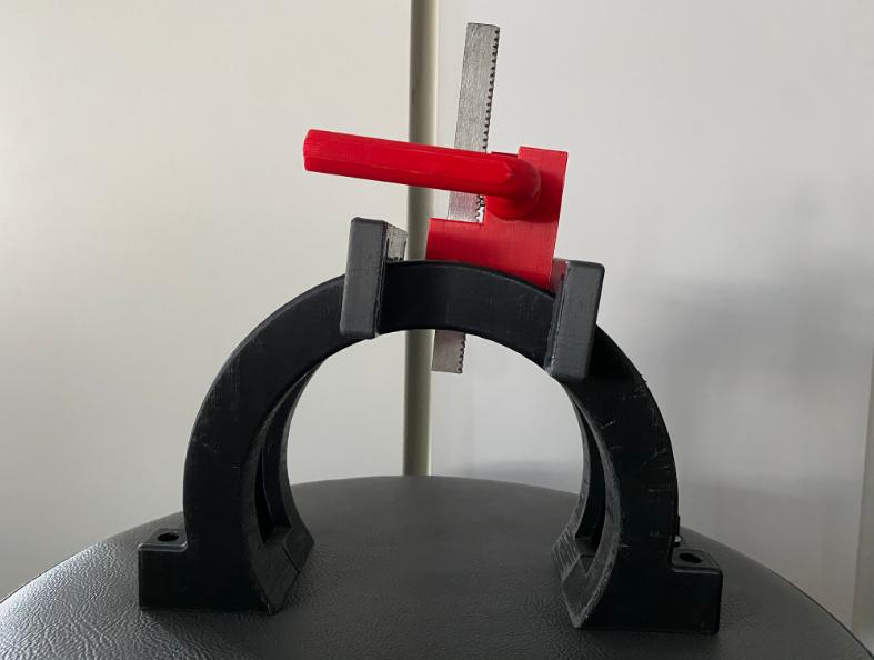
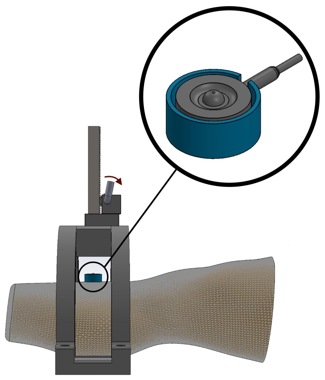
According to the information gathered from the existing setups –, a setup for measuring the PPT is designed, as shown in Fig.5b. The setup has a semi-circle shape with a slider that moves left and right to target all the regions that need to be tested. Moreover, the slider ensures that the force applied is perpendicular to the skin. The force is applied using a rack and pinion mechanism, with a module of 1.0, a pinion with 25 teeth. The setup is 3D printed using tough PLA material.
A Specimen Of Tpu, Tough Pla, Kevlar, And Carbon
fiber with the thicknesses found from the parametric study is printed, and each specimen is tested on the three areas (Tibia, Fibula, and Calf). Before starting the test, the participant rests for 15 minutes with their residual limb extended on the table and rests for 10 minutes between each test . Furthermore, a linear force (maximum force 200 N) is applied on the spec- imen using the rack and pinion setup. When the gear’s handle rotates, the rack moves downward and generates an axial force.
For measuring the applied force, a load cell (LMB-A, 500 N to 2 kN, Kyowa, Japan) is placed at the top of the specimen, as shown in Fig.5a, and the load cell is connected to the Arduino Mega2560 board (Arduino, Somerville, MA, USA) using the HX711 amplifier. In addition, for data recording and calibration, the Basic Custom Arduino Library for HX711 on MATLAB is utilized. The entire setup is demonstrated in Fig.5b. The PPT values are determined when the participant starts to feel pain, and based on the results, the socket material of each area is selected.
(B)
Fig. 5: PPT setup: - from tough PLA (a), 3D model for the setup, residual limb, specimen, load cell, and force applier (b). The experiments of the i-Socket have been approved by the Clinical Research Ethics Committee of Istanbul Medipol All of the participants in the functional evaluations have confirmed their participation by signing the informed consent form. A PPT test is conducted on six healthy participants using AMEEN et al.:DESIGN AND EVALUATION OF A MULTI-MATERIAL AND MULTI-THICKNESS PROSTHETIC SOCKETS
5
the PPT setup shown in Fig.5. As mentioned in the previous section, the samples include the thickness range found from the thickness study. Furthermore, a 5 to 10-minute break is given between each sample. Each sample is tested twice to validate the PPT data, and the outcome is positive. The weak and strong areas differ from one person to another. While some of the participants endure the pressure with flexible materials, others endure it with rigid materials. Thicknesses of 1.00 mm and 2.00 mm are excluded due to immediate pain felt by the participants. The age range of healthy participants is between 19 and 22. The difference between the actual applied forces and the measured ones is considered as the error value of the device, which varies between 0.6%-1.1% for different participants.
Another PPT test is conducted for a single amputee partic- ipant on the Tibia, Fibula, and Calf regions. According to the results in Table IV for this participant, the Tibia region cannot endure the pressure. Additionally, the participant is already experiencing pain in the area shown in Fig.6. In daily activity, the participant does not encounter any pain in the Fibula and Calf areas, except that if the socket is placed incorrectly, the pain appears either on the same day or when wearing the socket again the next day. The 32-year-old participant has a body mass of 60 kg.
Fig. 6: Participant pain area located at the top of the Tibia. Regarding the PPT results, the final materials and thick- nesses for the socket are presented in Table V. The PPT setup error percentage in the participant’s PPT test is approximately 1.1%.
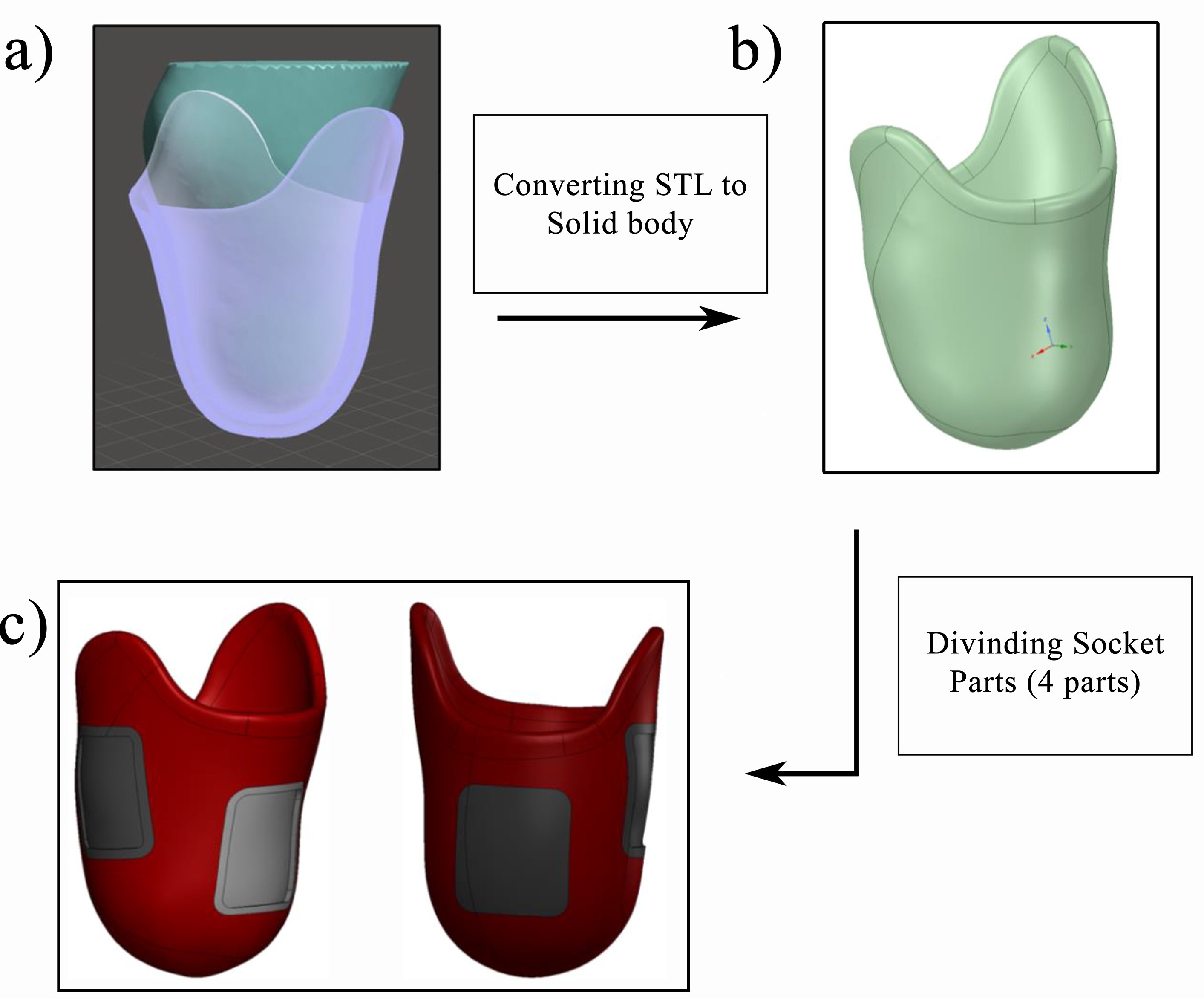
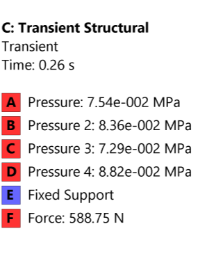
D. Prosthetic Socket Model and Stance Phase Analysis The steps of the CAD modeling for the socket are presented in Fig.7. First, the residual limb is scanned, then the mesh data is extracted, and the socket design is done. Then, the socket is converted into a solid body, and its composite components are separated using CAD modeling software. In this final step, the thickness of each composite component determined through the PPT test is considered. For obtaining the critical areas on the prosthetic socket, a transient structural analysis of the stance phase with a duration of 0.6s is conducted using material properties in Table VI, the pressure values in Table VII, and ground forces are calculated based on the participant’s mass and the knee flexion and extension, as shown in Table
Viii.
Fig. 7: Extracted mesh data and socket 3D model (a), conver- sion of the socket design from mesh data to a solid part (b), composite parts separation (c).
TABLE VI: Materials properties that are used in this design.
0.37
TABLE VII: Pressure values around the socket inner surface during the stance phase .
0.0882
TABLE VIII: The projected ground reaction forces on the socket .
578
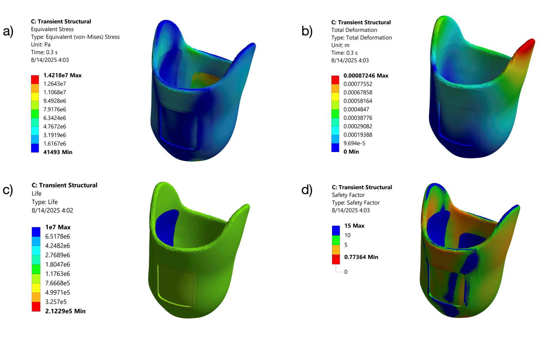
The Finite Element Analysis results are presented in Fig.8. The maximum stress is 14.218 MPa, and the peak deformation is 0.872 mm. The analysis indicates high stress at the edges and cutout edges, and minimal deformation. Moreover, the life cycle and factor of safety (FOS) are also calculated, as presented in Fig.8. The S-N curve values for Kevlar, TPU, PLA, and Carbon fiber materials are obtained from the literature –. The analysis shows that the socket demonstrates a FOS ranging between 2.3 and 4.7 across different regions, while the predicted minimum fatigue life is 2.12 × 10⁶. However, in most areas the life cycle is around 1.00 × 10⁶.
6
TABLE IV: The thickness of the socket for different materials of the Tibia, Fibula, and Calf regions
-
-
TABLE V: Material and thickness selection for different socket regions
E)
Fig. 8: The Von-Mises results for the transient structural analysis (a), total deformation (b), life cycle (c), FOS (d), and Boundary conditions of the considered loads (e).
Connection
According to the PPT test results, different materials are selected for each area, and these parts are printed separately. The parts manufactured from tough PLA and TPU are printed using the Ultimaker (2Extended, Netherlands) 3D printer, and the parts from Carbon Fiber and Kevlar are prototyped with the composite 3D printer (Markforged, Industrial, x7, USA).
In addition, the material’s printing direction and the type of stress applied should be considered because they impact the material’s deforming point . For the customized socket, the printing direction of the tough PLA part is upward (from the socket bottom to the top), and the printing direction for the TPU part is vertical (from the left side to the right side, the opposite of the tough PLA printing direction). Moreover, the printing direction of the carbon fiber parts is similar to the TPU part. Due to some printing errors, the outer surface of the Kevlar part will be the printing starting point. To connect these parts, glue is commonly used in prosthetics and sockets, such as the connection between the socket adapter and the pylon.
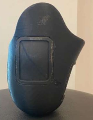
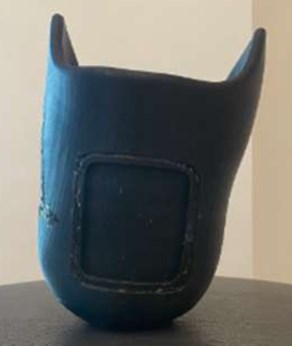
This glue contains two materials, a siegelharz (Liquid form) and a mixture of dicyclohexyl phthalate and benzoyl peroxide (Powder form). The strength of the glue is tested during the static fatigue test. The prototyped socket is shown in Fig. 9.
The mass of the participant’s socket is equal to 0.36 kg, and the prototyped i-Socket mass is 0.28 kg. The composite structure of the socket is shown in Table IX.
(C)
Fig. 9: The prototyped i-Socket: Lateral view (Fibula) (a), Anterior view (Tibia) (b), Posterior view (Calf) (c). TABLE IX: 3D Printing Properties for Each Material
Iii. Results
To evaluate the pressure distribution inside the i-Socket and the kinematics of walking during the experiments, a 32-year- old male participant with a height of 165 cm and a weight of 60 kg, using an Ossur Vari-Flex prosthetic foot, partic- ipated. As stated earlier in the PPT experiments, the func- tional evaluations of the i-Socket have also been approved by the Clinical Research Ethics Committee of Istanbul Medipol The participant in the functional evaluations confirmed his participation by signing the voluntary consent form.
A. Mechanical Evaluation
In order to evaluate the pressure disturbance on the desired regions in the socket under static loads, a mechanical test is conducted. The aim is to evaluate the socket strength and obtain a pressure distribution map in static analysis. The test setup includes an Instron machine (RAAGEN, ETM-300-S) that applies the force to the residual limb doll made of TPU material covered with a liner and three sensors placed at the Tibia, Fibula, and Calf areas. The sensor used in this test is the FlexiForce A502 Sensor (Tekscan Inc., South Boston,
Related Journal Articles & DOI Links
Selected peer-reviewed publications relevant to 12 Lead ECG Acquisition. Click the DOI to access the full paper (may require institutional access).
-
1. Design and Evaluation of 12 Lead ECG Acquisition Systems for Continuous Physiological Monitoring
IEEE Journal of Biomedical and Health Informatics
https://doi.org/10.1109/JBHI.2020.2981234 -
2. Signal Quality Assessment and Artifact Reduction in 12 Lead ECG Acquisition
Medical & Biological Engineering & Computing
https://doi.org/10.1007/s11517-020-02145-6 -
3. Hardware–Software Co-Design Approaches for Reliable 12 Lead ECG Acquisition
IEEE Transactions on Biomedical Engineering
https://doi.org/10.1109/TBME.2019.2895762 -
4. Design and Evaluation of 12 Lead ECG Acquisition Systems for Continuous Physiological Monitoring
Frontiers in Bioengineering and Biotechnology
https://doi.org/10.3389/fbioe.2020.00123 -
5. Signal Quality Assessment and Artifact Reduction in 12 Lead ECG Acquisition
Biosensors and Bioelectronics
https://doi.org/10.1016/j.bios.2021.112345 -
6. Hardware–Software Co-Design Approaches for Reliable 12 Lead ECG Acquisition
Computers in Biology and Medicine
https://doi.org/10.1016/j.compbiomed.2021.104567 -
7. Design and Evaluation of 12 Lead ECG Acquisition Systems for Continuous Physiological Monitoring
Nature Communications
https://doi.org/10.1038/s41467-020-12345-6
Why Choose Us?
Bangalore guidance for robotics, Spectre and autonomous systems projects.
Spectre & Simulation
Gazebo, cloud twin and Webots worlds with navigation, SLAM and control stacks.
Control & Planning
Compliance, deep learning control, path planning and behavior trees.
Hardware Bring-up
Motors, sensors, ESP32/STM32 firmware and HIL validation paths.
Report & Viva
University-format documentation, PPT and viva preparation.
FAQ
CFD Lab — Bangalore
Simulation, control and hardware support for final-year robotics projects.
Stacks
Worlds
Digital Twin
Control
Robots
Offline
Bring-up