Comprehensive Survey
Manender Yadav1,2, Shreyansh Shukla3, Varsha Kiron4, U. Deva Priyakumar2, Maitreya Maity1 Abstract—Bioimpedance is an extensively studied non-invasive technique with diverse applications in biomedicine. This compre- hensive review delves into the foundational concepts, technical intricacies, and practical implementations of bioimpedance. It elucidates the underlying principles governing bioimpedance measurements, including the relevant physics equations employed for estimating body fluid levels. Moreover, a thorough exam- ination of the prevalent single-chip analog front end (AFE) available in the market, such as AD5933, MAX30001, AD5940, and AFE4300, is conducted, shedding light on their specifications and functionalities. The review focuses on using bioimpedance to assess thoracic impedance for heart failure detection by utilizing the relation between lung water and heart failure. Traditional techniques are compared with bioimpedance-based methods, demonstrating the latter’s efficacy as a non-invasive tool for cardiac evaluation. In addition, the review addresses the tech- nical limitations and challenges associated with bioimpedance.
Pertinent issues such as contact impedance, motion artifacts, cal- ibration, and validation regarding their impact on measurement precision and dependability are thoroughly examined. The review also explores strategies and advancements in using artificial intelligence to mitigate these challenges.
Index Terms—Bioimpedance, Thoracic fluid, Total body water, Body composition, Heart failure, Biosensors, Analog front end.
I. Introduction
The field of bioimpedance has been making huge progress recently, revolutionizing the way we assess various physiolog- ical parameters . Bioimpedance-based methods, which are non-invasive and quick, have been receiving increased interest in both clinical practice and research studies. Electrical proper- ties of tissues and bioimpedance provide valuable insights into the physiological characteristics of the body, e.g., water, fat, protein, etc. . Cardiovascular diseases, which caused 20.5 million fatalities in 2021, are the leading cause of mortality in the whole world. The most common cause of thoracic fluid accumulation is congestive heart failure (CHF). Traditionally, the detection of thoracic fluid relied on invasive and time- consuming techniques such as pathological tests, CT scans, MRI, X-rays, etc. . However, bioimpedance can play a major role in measuring and analyzing thoracic fluid content more efficiently. This comprehensive systematic literature re- view article explores the fundamentals, theory, and concepts of bioimpedance, with a particular focus on the advancements This work is funded by 1IHub-data, International Institute of Information
Technology Hyderabad
2Centre For Computational Natural Sciences and Bioinformatics, Interna- tional Institute of Information Technology, Hyderabad- 500032
In Basic Sciences, Mumbai
4AIG Hospital Banjara hills (8-2-594/FF, Zahara Nagar, Banjara hills)
Hyderabad
made in single-chip sensors and their application in thoracic bioimpedance measurement. This systematic literature review (SLR) begins with a detailed description of the article selection method section II, which outlines the research questions guiding this arti- cle, the methodological procedures used for paper selection, and a comprehensive list of the databases searched for rel- evant research papers. The next section III, Bioimpedance basics, is devoted to explaining the foundational principles of bioimpedance. This section provides a thorough exploration of the theoretical underpinnings, describing the interaction of electrical currents with biological tissues and its role in generating valuable information. The following section IV, Chips and devices, focuses on technological advancements in single-chips. These innovations have significantly improved the practicality and versatility of bioimpedance measurements.
Technical specifications of prominent single-chip sensors are presented, along with an extensive examination of studies employing these devices. The main emphasis of this article is on thoracic fluid detection, which is a practical application of bioimpedance technology. This topic is comprehensively addressed in the dedicated application section V. Here, the au- thors objectively assess how bio-impedance-based techniques compare with conventional methods, elucidating their inherent strengths, limitations, and potential for further improvement.
Their analysis is based on a rigorous evaluation of accuracy, reliability, and efficiency. Next, the authors offer an extensive exploration of the integration of Artificial Intelligence (AI) within the realm of bioimpedance in section VI. This section illustrates how AI enhances the capabilities of bioimpedance technology in various applications, with an emphasis on the underlying scientific principles. In the subsequent section VII, the authors address the major challenges faced by the re- searchers in this field, acknowledging the inherent limitations of bioimpedance technology. Finally, we concluded the review work in section VIII.
Overall, this review article aims to serve as a valuable resource for researchers, clinicians, and healthcare profession- als interested in the field of bioimpedance. By presenting a detailed analysis of bioimpedance basics, theory, and concepts, as well as the latest single-chip sensors available in the market, we hope to foster a deeper understanding of this technology and its applications in thoracic fluid detection.
Ii. Article Selection Method
A systematic literature review (SLR) is a research method- ology that employs a structured and comprehensive approach
2
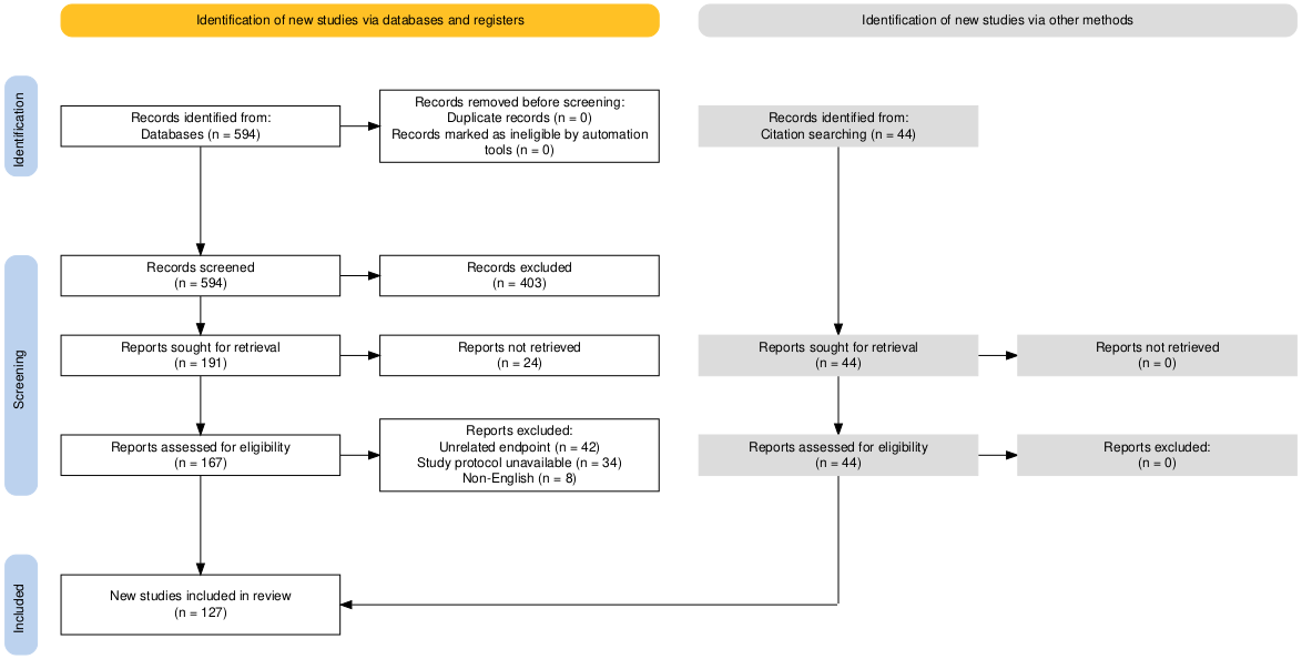
to identify, select, and evaluate relevant studies to answer a specific research question . The methodology involves formulating research questions, defining inclusion and exclu- sion criteria, and conducting a thorough search of multiple databases. In this review, the authors conducted a compre- hensive search of several databases supported by Google and PubMed. The search spanned from 2015 to 2025 and included all relevant publications published within this pe- riod. The authors used the following keywords to search for relevant publications: bioimpedance, body composition, fluid management, health monitoring, heart failure, impedance analyzers, machine learning, artificial intelligence, single-chip biosensors, thoracic fluid, tissue impedance, and total body water. The search strategy yielded 594 articles that were screened for relevance based on their abstracts as shown in Fig.1. The selected articles were then thoroughly studied to identify important papers which were cited but were outside the search year and were included in this review. Finally, 127 articles were included in this comprehensive review article.
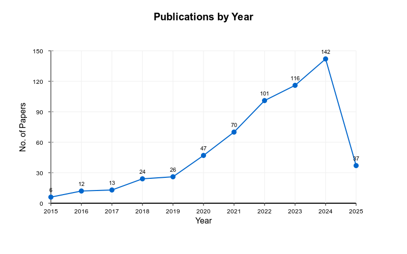
The number of articles published in this domain for the past 10 years is shown in Fig.2. There is a gradual increase in the number of papers published every year related to this domain, the sudden decrease in 2025 is likely because the data only represents approximately the first quarter of the year. When analyzed in depth, the recent papers were found to be more relevant and involved the use of Machine Learning methodologies. This signifies a shift from the traditional methods to the more advanced AI-based research solutions.
The following sections discuss the findings of this in-depth literature review.
Iii. Bioimpedance Basics
Bioimpedance refers to how biological systems or tissues interact with electricity. A small potential difference is applied to the biological tissue and measurement of the resulting electrical signals is analyzed to obtain various physiolog- ical parameters. Bioimpedance measurements are typically performed using electrodes placed on the skin’s surface or by utilizing specialized sensors. Multi-frequency current is applied to the tissue of interest, depending on the specific application. The impedance of biological tissues arises from various components, including cells, extracellular fluid, blood vessels, and cell membranes. These components have different electrical properties, such as resistance (R) and reactance (X), which contribute to the overall impedance. Bioimpedance analysis (BIA) is commonly used to estimate body com- position parameters. In BIA, the impedance of the body is measured typically by passing a low-intensity AC current and then derives information about body fat, lean mass, hydration status, and other relevant parameters. Another application of bioimpedance is electrical impedance tomography (EIT), which involves measuring impedance changes at multiple points on the body’s surface. EIT can provide real-time imaging of the electrical properties within the body, making it useful for monitoring lung function, analyzing brain activity, and other medical applications. Bioimpedance has found ap- plications in various fields, including medicine, sports science, and nutrition. It offers non-invasive or minimally invasive ways to gather information about physiological conditions and can aid in diagnosing certain diseases, assessing body composition, monitoring hydration levels, and guiding therapeutic interven- tions.
Bioelectrical impedance analysis (BIA) and bioelectrical impedance spectroscopy (BIS) are techniques used to study tissues, providing valuable insights into their molec- ular composition and physical structure for diagnostic and prognostic purposes. The human body along with the organs and cells, exhibit structural heterogeneity, and their molecular composition varies due to dynamic biochemical reactions and the presence of electro-responsive components like ions, proteins, and polarized membranes. Despite the challenges in interpreting bioimpedance data, BIA/BIS has proven to be a powerful tool for evaluation and monitoring . BIA/BIS serves as the foundation for various diagnostic and monitoring systems. Its popularity can be attributed to three key factors: 1) It is a non-invasive and safe measurement method
2) It Can Be Easily Miniaturized
3) many technological formats exist for its implementation
A. Principal Behind Bioimpedance
Tissues are composed of cells and membranes, which are thin and have a high resistivity, functioning like capacitors. When high frequencies are used, the current can pass through these capacitors, and the outcome is influenced by both the tissue and the fluid inside and outside it. At lower frequencies, the membranes obstruct current flow, providing information only about the external fluid. Fat has a high resistivity, while blood reduces the resistivity.
Bioimpedance techniques employ electrodes that have a galvanic connection to the tissue. Bioimpedance measurement devices use electronic circuits and electrodes. In copper wires, electrons carry a charge, while in tissue, ions (mostly) carry the charge. The electrode is where the conversion of charge carriers from ions to electrons and vice versa occurs.
(1)
where ρ is resistivity of the tissue, Z denotes the impedance, L and A being the electrodes’ distance and cross-section area, respectively.
The above model is only for the homogeneous tissue and cur- rent band electrodes are far away from the pickup electrodes .
B. Bio-impedance equations from Maxwell’s equations Relevant Maxwell equation most for bioimpedance is :
(2)
where H is magnetic field [A/m], D denotes the electric flux density [coulomb/m2].
(3)
YADAV et al.: THORACIC FLUID MEASUREMENTS BY BIOIMPEDANCE: A COMPREHENSIVE SURVEY
3
Fig. 1. Article selection based on PRISMA framework. Fig. 2. Articles based on the above-mentioned keywords by year where E denotes the electric field [V/m], ε0 is the permittivity of vacuum [farad (F)/m] and electric polarization is repre- sented by P(dipole moment per volume [coulomb/m2]).
When the magnetic component is ignored, Equation (2) be-
(4)
where σ is the conductivity [S/m]. We assume a small voltage amplitude (V) across the material, thus making so the system linear. As sinusoidal functions in input, we can represent it with complex notation as a
Ee (Space Vectors), Where The
permittivity e = ereo under these conditions, lossy dielectric can be characterized by a complex dielectric constant,
(6)
where, i = √−1 . using this and applying equation 2 on a capacitor of area A and dielectric thickness L. But equation (2) is in a differential form, and the discontinuous interface will have discontinuity thus, we will use Gauss Law as an integral form. The equations above are not just extremely robust but are valid under non-homogeneous, nonlinear, and anisotropic conditions. The bio-impedance equation, which is
(7)
In which (Y) denotes the admittance [siemens, S], (G) symbol- izes the conductance [S], ( ω ) represents the angular frequency [rad/s], (C) is the capacitance [farad, F] and i = √−1.
The equation for impedance reveals that the fundamental impedance model is essentially a model of admittance. In this model, the conductive and capacitive components are physically parallel. It’s crucial to note that this model primarily depicts a dielectric model with dry samples.
We have obtained an impedance equation for a circuit. This makes the next question about what is impedance. It is the effective resistance of an electrical circuit to alternating current (ohmic resistance and reactance); to be more specific, it is the resistance a circuit or components offers to current flow in a circuit at a specific frequency unit ohms (Ω). It changes due to the reactive components non-reactive - resistor (same for AC and DC current) reactive components - mainly capacitor and inductor.
1) Capacitor: The impedance of this reactive component displays an inverse relationship with frequency, being sub- stantial at low frequencies and minimal at high frequencies.
4
Capacitors store an electrical charge. The capacitor charges and discharges to resist change in the current. In a capacitor, the faster the direction changes - the lower the capacitive resistance.
2) Inductor: The impedance of this reactive device displays a direct relationship with frequency, being minimal at low frequencies and significant at high frequencies. Coils and reactors are common sources of inductive resistance. These components establish a magnetic field that opposes changes in the direction of alternating current. Specifically, in an inductor, the faster the AC current’s direction shifts, the higher the inductive resistance it exhibits.
3) Formula governing capacitive impedance: The formula
(10)
where, f is frequency, Xc is Capacitance, R is non reactive resistance and XL Inductance thus making the magnitude
(11)
Where R is the nonreactive impedance or simple resistance.
(12)
Thus, for ease, it can be replaced in the above equations. To measure impedance in the physics lab, we used a lock- in amplifier.
To Measure Different Impedance
Ohm’s law: relation with potential difference and current
(14)
for 2 terminal circuits, it is the ratio of the complex repre- sentation of the sinusoidal voltage difference. For sinusoidal
(17)
One point to note is that the inductor leads by a phase of π/2, and the capacitor lags by the same.
C. Dependence On Frequency And Input Signal
The way biological tissue conducts electricity is affected by the frequency of the signal it is exposed to. Tissue can be modeled as either a conductor or a dielectric, depending on the frequency range. Below 100 kHz, tissue behaves mostly as an electrolytic conductor, with capacitive effects due to electrode- electrolyte interfaces and cell membranes. These effects can be measured with high-resolution techniques, such as lock- in amplifiers, to reveal the dielectric properties of tissue at low frequencies. Above 50 kHz, the tissue becomes more dielectric, with its properties approaching those of water at very high frequencies (around 18 GHz). Water has a charac- teristic relaxation frequency where its dielectric loss factor is maximal.
To measure the bioimpedance or bioimmittance of tissue, different types of waveforms and electrode configurations can be used. Sinusoidal waveforms are preferred to overstep or pulse waveforms, as they avoid nonlinearities and heat gen- eration that may alter the tissue properties. Single-frequency (BIA) or multi-frequency (BIS) signals can be injected into the tissue with low amplitude and measured with a voltage meter.
The impedance varies with frequency, showing two main dispersions: alpha and beta. Alpha dispersion occurs when the applied signal frequency is in between 10 Hz to 10 kHz and is related to the membrane polarization of cells.
Beta dispersion occurs when it is in between 10 kHz to 10 MHz and is related to the interfacial polarization of tissue components. Two other dispersions, delta and gamma, are less relevant for bioimpedance measurements, as they occur at higher frequencies (above 100 MHz) and are influenced by water molecules and macromolecules.
To measure bioimpedance accurately, a four-electrode (tetrapolar) system is recommended, as it reduces the contact resistance errors that may arise from using two electrodes for both current injection and voltage sensing. A four-electrode system consists of two pair of electrodes, one pair is used to apply the current and the other pair to measure the voltage.
The transfer impedance is calculated by dividing the measured voltage by the applied current. If no voltage is measured, the transfer impedance is zero, which means that no signal transfer occurs between the electrodes.
Bioimpedance measurements can be used to analyze and infer biological events and underlying principles, such as tissue composition, hydration status, blood flow, cell viability, etc.
Bioimpedance can also be integrated into wearable devices and connected to the Internet for remote monitoring and diagnosis. To extract relevant physiological or compositional information from bioimpedance data, equivalent circuit models are used to represent the electrical properties of tissue. Some examples of circuit models are the Randles circuit, the Cole-Cole circuit, YADAV et al.: THORACIC FLUID MEASUREMENTS BY BIOIMPEDANCE: A COMPREHENSIVE SURVEY
5
and the Cole equation. These models use different combi- nations of resistors, capacitors, constant phase elements, and Warburg impedances to fit the impedance data and estimate parameters such as resistance, reactance, phase angle, etc .
1) Contributions to Ionic Conductivity: Kohlrausch demon- strated that the conductivity, represented as σ, is the aggrega- tion of individual contributions from anions (-) and cations (+).
The current density, denoted as J [A/m2], for a single pair of
(19)
In these equations, n is the ion concentration per volume, z is the valency of an atom (the number of transferable electrons), e is the charge of the electron [C], and v is the ion velocity [m/s]. F represents the Faraday constant [C/mol], c is the concentration [mol/m3], g is the activity coefficient (which accounts for possible incomplete electrolyte dissociation, with g ranging between 0 and 1), and m signifies the mobility [m2/Vs]. The current density, J, must include contributions from each species of negative and positive ions.
It’s important to note that determining individual ion species’ activity coefficients can be challenging due to electroneutrality - an electrolyte cannot consist solely of anions or cations.
From this, we can then compute total conductivity and molar conductivity. It’s also worth noting that friction (as per Stokes’ law f=6πνav) will also be a factor.
D. Sensitivity And Geometry Of Electrode
The electrical behavior of biological tissues in bioimpedance analysis is often represented through electrical circuit mod- els, a key aspect of the network analysis and synthesis method.The following models can be used to analyze and interpret bioimpedance measurements.
1) Randles circuit: One of the most commonly used circuit models in bioimpedance is the Randles circuit. The model incorporates a resistor denoted by (R), a constant phase element (CPE) as its constituent parts. The Randles circuit
(20)
Where ZRand is the impedance of the Randles circuit, Q is the constant phase element, α is the Warburg coefficient, and W is the Warburg impedance .
Another Commonly Used Circuit
model is the Cole-Cole circuit, which is given by:
(21)
Where ZCC is the impedance of the Cole-Cole circuit . The Cole equation is a simplified version of the Cole-Cole circuit, which assumes that the constant phase element is a
(22)
where ZCole is the impedance of the Cole equation. In addition to these circuit models, bio-impedance measure- ments can also be analyzed to model the complex dielectric response of biological tissues using equivalent circuit models based on the how the relaxation times are distributed.
Overall, the network analysis and synthesis approach provides a powerful tool for analyzing and interpreting bio-impedance measurements. By using these electrical circuit models, re- searchers can understand the underlying physiological pro- cesses that give rise to bio-impedance measurements.
One important property is the resistivity Rtotal of the tissue, which represents its inherent resistance to the flow of electric current. The resistivity can be complex, denoted as
(23)
where R denotes the real part and RL + RC denotes the imaginary part. The conductivity σ of the tissue is the reciprocal of the
(24)
It represents the ease with which electric current flows through the tissue. The permittivity ε of the tissue describes its ability to store electrical energy in an electric field. It can also be complex,
Ε = Ε′ + Iε′′
where ε′ and ε′′ are the real and imaginary part respectively. The complex permittivity can be related to the complex
(25)
where ε0 denotes the permittivity of vacuum as a constant. Similarly, the impedance z of the tissue is also the opposition
(26)
where ωis the angular frequency.
(27)
Often, the Cole-Cole model serves as a description of how tissue impedance behaves at different frequencies. It is given
(28)
where ZCC is the impedance given by the Cole-Cole model , R0 denotes the DC resistance, relaxation time is given by τ, and α is the shape parameter.
These physical properties of tissue play a crucial role in understanding and interpreting bioimpedance measure- ments. By considering the resistivity, conductivity, permittiv-
Reference
Divala et.al.
Height2(Cm)
Resistance (Ω) + 0.910 × sex + 0.307 × age (years) + 0.249 × Weight + 0.015 × Reactance (Ω) −2.152
50 Khz
Hannan et.al.
Height2(Cm)
Resistance (Ω) + 2.971 × sex + 0.1889 × Weight + 5.4641
200 Khz
Sun et.al.
50 Khz
Sun et.al.
50 Khz
Kushner et.al.
50 Khz
E. Bioimpedance based equations for Total Body Water (TBW) In recent years, BIA has evolved significantly to aid in assessment of body composition parameters. This section provides with a Table (I) of validated equations that use impedance measurements to estimate TBW. However, it is important to emphasize that all these equations are empirically derived and, consequently, are population-dependent. This dependency necessitates careful consideration when applying these equations to subjects whose demographic characteristics differ from those in the original validation groups. Here, sex is coded as male = 1 and female = 0.
Iv. Chips And Devices
A bioimpedance system typically consists of the follow- ing components: a voltage signal excitation, a voltage-to- current converter to connect to the bioimpedance sensor’s current injecting electrodes, a voltage measurement front- end connected to the sensor’s pertinent electrodes, and the back-end analog or digital processing of the recorded sig- nal. Individual building blocks of commercially available chips can be used to manufacture instruments, and full- custom CMOS chip designs can be used to generate op- timized and application-specific solutions. However, com- plete impedimetric commercial chip solutions also exist .
Based on our review of commercially available bioimpedance measurement solutions, we have identified the following
Afe4300, Afe4500, Afe4960, Ams As7058, Max30001G,
MAX30009 and MAX86178. Out of these, eight key in- tegrated circuit platforms that offer varying capabilities for impedance measurement applications. Table II provides a comprehensive comparison of these chips. This comparison can serve as a guide for researchers and developers selecting the appropriate chip according to their specific requirements for biomedical monitoring, wearable health devices, or clinical diagnostic systems.
A. Ad5933
It comes with a high speed 12-bit analog-to-digital con- verter (ADC) and a frequency generator system for high accuracy impedance conversion. The system incorporates a Digital Signal Processing (DSP) engine that takes the sam- pled impedance response and calculates its discrete Fourier transform (DFT). The result of this DFT computation is real (R) and imaginary (I) values at various output frequencies.
Other:
is also capable of measuring in the range of 100 Ωto 1 kΩwith help of an additional circuitry. Calibration of the system allows for the straightforward determination of both the relative phase and the impedance magnitude at each frequency measured during the sweep. This is done using the contents of the real and imaginary registers, read from the serial I2C interface. However, this chip is not suitable for bioimpedance measurements at low frequencies. This is because the chip has a limited frequency range and resolution, and its accuracy decreases at low frequencies. Also, it is designed for two electrode measurements. It can be used with four electrodes but will require additional circuitry. Although it is configured for dual electrode configuration, Margo et al. designed a custom circuit to use it along with tetrapolar electrode settings to control the contact impedance between the electrodes and the material. They used the designed system for studying the conductivity of various physiological samples . Seoane et al. also designed an Analog Front End (AFE) and used it along the AD5933 circuit to fully adapt it to a four-electrode strategy, making it suitable for biomedical applications . It consisted of two voltage-to-current converters (V2CCs) and a current- to-voltage converter (CVC). The V2CCs convert the voltage signal from the AD5933 chip to a current signal, which is then applied to the Tissue of interest. The CVC converts the current signal from the biological tissue to a voltage signal, which is then fed back to the AD5933 chip for measurement. The maximum load dynamic range is determined by the overall gain introduced by the combined effect of both V2CCs and the resistor Rref at the input Rfeedback. Overall, the AFE enables the use of AD5933 in biomedical applications by adapting it to a four-electrode strategy and providing a simple and effective way to convert voltage signals to current signals and vice versa.
YADAV et al.: THORACIC FLUID MEASUREMENTS BY BIOIMPEDANCE: A COMPREHENSIVE SURVEY
B. Ad5940
It is the newest iteration in the AD59xx series. It is spe- cially designed for bio-impedance measurements. It has two excitation loops along with a common measurement channel.
The first excitation loop can generate signals from 0 Hz up to 200 Hz. Along with this, it also has a second excitation loop which can generate signals up to 200 kHz. It comes with a 16-bit (800kSPS) multichannel ADC along with input buffers.
Featuring a built-in antialiasing filter and a programmable gain amplifier (PGA), the system enables the user to select the specific measurement input channel using an integrated input multiplexer (mux) positioned prior to the ADC. The sensor is connected to the internal analog excitation and measure- ment blocks using a programmable switch. Beyond impedance measurements, this chip also functions as a connection point for external trans-impedance amplifier resistors and calibration resistors. Furthermore, its programmable matrix switch allows multiple electronic measurement devices to share the same electrodes. To ensure stable performance with minimal drift for its 1.82 V and 2.5 V components, the chip incorporates an internal reference source. The serial peripheral interface (SPI) allows for direct register writes, which can be used to control the system. Alternatively, it can also be done through a pre-configurable sequencer for independent operation of the analog front-end (AFE) chip. Measurement instructions and outcomes are stored in separate command and data FIFOs.
Various FIFO-related interrupts signal when the FIFO is full. The AFE sequencer also manages multiple general-purpose input/output pins (GPIOs) . In a study by Dutt et. al, the AD5940 sensor was utilized as a part of the bioimpedance measurement system for fluid monitoring in Dengue disease
. The Eval-Aducm3029 Microcontroller Development
board, through the SPI protocol, was responsible for config- uring the AD5940 sensor digitally to enable 4-wire whole- body bioimpedance measurements. The authors used it to generate a maximum output voltage of 1.2V (peak to peak) and limited the alternating current (AC) amplitude to a maximum of 400µA (rms) using a current-limited resistor. The AD5940 sensor performs measurements from 1 kHz to 100 kHz with 1 kHz increments at a rate of 20Hz. It also utilizes a DFT accelerator to determine the real and imaginary components of the measured bioimpedance. The stability and accuracy of the AD5940 single-chip converter were validated through capacitor test measurements in a study by Zhivkov et al. In the capacitor test measurements, the AD5940 was used to measure the impedance of capacitors at a single frequency of 1 Hz . The stability of the converter was evaluated by monitoring the impedance values over time. A stable converter would exhibit consistent impedance measurements without significant fluctuations or drift. The accuracy of the AD5940 was assessed by comparing the measured impedance values with the known values of the capacitors used in the test.
AD5940 maintained consistent impedance measurements over time, indicating good stability and accurate operation. These stability and accuracy validation tests provide confidence in the performance of the AD5940 single-chip converter for impedance microbiology studies. In a study by Xia et al., it was used for ankle impedance analysis, interfaced with a microcontroller enabling impedance meaasurements ranging from 0 to 2000 Hz . The system utilized a programmable AC voltage generator, operating at a frequency of 50 kHz, with the AC amplitude restricted to a maximum of 500 µA (rms) via a current-limiting resistor. This configuration provided measurement accuracy to two decimal places, mak- ing it particularly suitable for clinical applications such as monitoring lower extremity edema in patients diagnosed with heart failure (HF). In another study presented by Asiain et al., it was used to design a wearable device for measuring electrodermal activity (EDA) in a constant alternating current setup . The microcontroller, specifically the MAX32630 FTHR kit, interacted with the AD5941 via the serial peripheral interface (SPI) to facilitate impedance measurements. This allowed for the generation of high resolution voltage signals and maintained a maximum current through the skin at 10µA.
The AD5941 performed measurements over a frequency range of 200 Hz to 200 kHz, utilizing a dual measurement loop for enhanced precision in EDA signal capture. Furthermore, it incorporated a discrete Fourier transform (DFT) hardware block to process the signals, effectively enabling the extraction of complex skin impedance values, thereby improving the overall reliability of the EDA data collected by the wearable device.
C. Afe4300
The AFE4300 is a low-cost AFE featuring two distinct signal chains: one for body composition analysis and the other for weight measurement. A 6-bit digital-to-analogue converter (DAC) is used for the weight measurement, and an external resistor controls the gain of the instrumentation amplifier (INA). For ratiometric measurements, a circuit is also included that drives an external bridge/load cell at a fixed 1.7 V. A 6- bit, 1-MSPS DAC and an internal pattern generator are used to create the sinusoidal current for bioimpedance analysis. This sinusoidal current can be applied to the body by a voltage-to- current converter to determine the body composition eventu- ally. A differential amplifier measures and rectifies the voltage across the terminals due to the impedance. The amplitude is extracted and measured by the 16-bit ADC . In a study by Dahlmanns et al. AFE4300 serves as the analog front- end for the system for tetrapolar bioimpedance spectroscopy (BIS) in bandages to enable long-term monitoring of tissue integrity, specifically for chronic wounds such as ulcus cruris.
It generates excitation frequencies ranging from 1 kHz to 255 kHz. It injects a current of 375 µA into the body, ensuring that the current remains below 500 µA, even with a +20% error, to prevent any health impairment . Since AFE4300 is designed to be able to handle upto 3 tetrapolar-electrode configurations for impedance measurements. Sanchez et al.
evaluated its potential to be used for various biomedical applications. Along with its interesting features to be used as a body composition impedance meter, the authors used it to monitor ventilatory bioimpedance varying over time .
Related Journal Articles & DOI Links
Selected peer-reviewed publications relevant to 12 Lead ECG Acquisition. Click the DOI to access the full paper (may require institutional access).
-
1. Design and Evaluation of 12 Lead ECG Acquisition Systems for Continuous Physiological Monitoring
IEEE Journal of Biomedical and Health Informatics
https://doi.org/10.1109/JBHI.2020.2981234 -
2. Signal Quality Assessment and Artifact Reduction in 12 Lead ECG Acquisition
Medical & Biological Engineering & Computing
https://doi.org/10.1007/s11517-020-02145-6 -
3. Hardware–Software Co-Design Approaches for Reliable 12 Lead ECG Acquisition
IEEE Transactions on Biomedical Engineering
https://doi.org/10.1109/TBME.2019.2895762 -
4. Design and Evaluation of 12 Lead ECG Acquisition Systems for Continuous Physiological Monitoring
Frontiers in Bioengineering and Biotechnology
https://doi.org/10.3389/fbioe.2020.00123 -
5. Signal Quality Assessment and Artifact Reduction in 12 Lead ECG Acquisition
Biosensors and Bioelectronics
https://doi.org/10.1016/j.bios.2021.112345 -
6. Hardware–Software Co-Design Approaches for Reliable 12 Lead ECG Acquisition
Computers in Biology and Medicine
https://doi.org/10.1016/j.compbiomed.2021.104567 -
7. Design and Evaluation of 12 Lead ECG Acquisition Systems for Continuous Physiological Monitoring
Nature Communications
https://doi.org/10.1038/s41467-020-12345-6
Why Choose Us?
Bangalore guidance for robotics, Spectre and autonomous systems projects.
Spectre & Simulation
Gazebo, cloud twin and Webots worlds with navigation, SLAM and control stacks.
Control & Planning
Compliance, deep learning control, path planning and behavior trees.
Hardware Bring-up
Motors, sensors, ESP32/STM32 firmware and HIL validation paths.
Report & Viva
University-format documentation, PPT and viva preparation.
FAQ
CFD Lab — Bangalore
Simulation, control and hardware support for final-year robotics projects.
Stacks
Worlds
Digital Twin
Control
Robots
Offline
Bring-up