18
Implementation of an Innovative Bio Inspired GA and PSO Algorithm for Controller design considering Steam GT Dynamics
Sona College Of Technology, Salem-636005, India
St.Peters Engineering College, Chennai, INDIA.
Abstract
The Application of Bio Inspired Algorithms to complicated Power System Stability Problems has recently attracted the researchers in the field of Artificial Intelligence. Low frequency oscillations after a disturbance in a Power system, if not sufficiently damped, can drive the system unstable. This paper provides a systematic procedure to damp the low frequency oscillations based on Bio Inspired Genetic (GA) and Particle Swarm Optimization (PSO) algorithms. The proposed controller design is based on formulating a System Damping ratio enhancement based Optimization criterion to compute the optimal controller parameters for better stability. The Novel and contrasting feature of this work is the mathematical modeling and simulation of the Synchronous generator model including the Steam Governor Turbine (GT) dynamics. To show the robustness of the proposed controller, Non linear Time domain simulations have been carried out under various system operating conditions.

Also, a detailed Comparative study has been done to show the superiority of the Bio inspired algorithm based controllers over the Conventional Lead lag controller.
Keywords: BioInspired Algorithms, Power System Optimization, Genetic Algorithm, Low frequency Oscillations, Particle Swarm Optimization.
1. Introduction
Modern Bio Inspired Algorithms include a wide variety of Population based algorithms which can be applied to
Various Power System Optimization Problems. The
Phenomenon of stability of modern interconnected power systems has received a great deal of attention in recent years. One problem that faces power systems nowadays is
Interconnected Power Systems . Sometimes, These
oscillations sustain for minutes and grow to cause system separation, if adequate damping is not provided. A cost efficient and satisfactory solution to the problem of low
Frequency Oscillations Is To Provide Damping By
implementing Power System Stabilizers (PSS), which are supplementary controllers in the Generator Excitation
Systems .Designing And Applying The Pss Is A
complex phenomenon. In recent years, several approaches based on Modern control theory have been applied to PSS design problem. These include optimal control, adaptive control, variable structure control and intelligent control .
Despite the potential of modern control techniques, Power System utilities still prefer the conventional lead lag PSS
Structure .The Parameters Of Cpss Are Based On A
linearized model of the Power System. Since modern power systems are dynamic and non linear in nature, CPSS performance is degraded whenever the operating point changes from one point to another because of the fixed parameters of the stabilizer. Unfortunately, the conventional techniques are time consuming, as they are iterative and require heavy computation burden and slow convergence.

Recently, Bio Inspired optimization techniques like Genetic Algorithm, Evolutionary Programming, Simulated Annealing, Bacteria foraging, Particle Swarm optimization etc have been applied for PSS parameter optimization [7- 9].In this work, Genetic algorithm and Particle Swarm
Optimization Algorithms Has Been Implemented For
computing the parameters of the optimal controller including Steam Governor Turbine dynamics for Power System Stability.

The Main Objectives of this work are summarized as
Follows:
(1).To develop a linearized State Space model of the
Smib Model (Including Steam Governor Turbine
dynamics) with and without the damping controller. (2).To formulate a Damping ratio enhancement based
Optimization Criterion To Compute The Optimal Pss
parameters.
(3).To Compare The Computed Damping Ratios Of The
Conventional PSS (CPSS), Genetic based PSS (GAPSS) and Particle Swarm based PSS(PSOPSS) for damping the poorly damped Electromechanical modes of oscillation.
(4). To carry out Parameter Sensitivity analysis by performing Non linear Time domain based simulation to validate the robustness of the proposed controllers under wide variations of system operating conditions and also under variations in system parameter involved in the model.

2.1 System Model Under Study
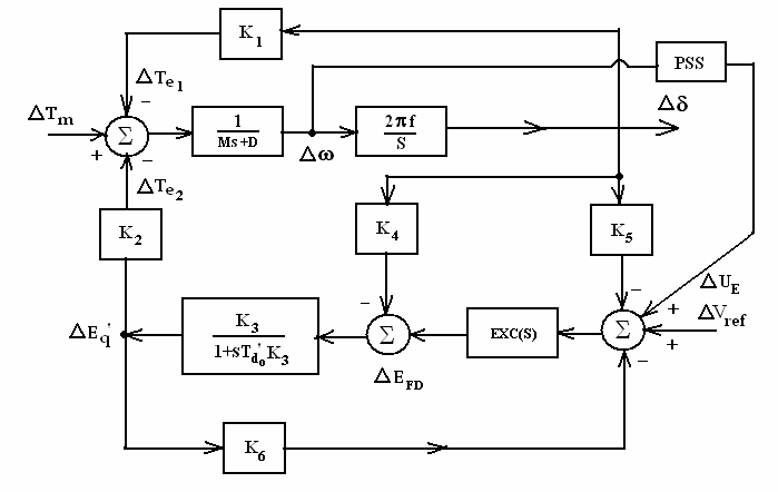
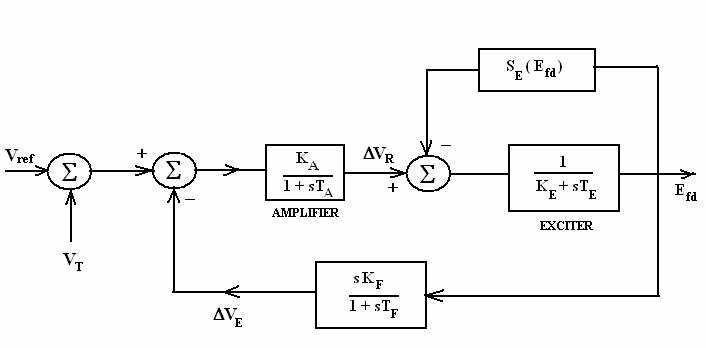
Fig.1.shows the Heffron Phillips block diagram of Single Machine Infinite bus model (SMIB) equipped with Type 1 Excitation system involving Amplifier, Exciter and Rate Derivative feedback compensation as in Fig(2).
In all the classical model analysis for SMIB system, the mechanical power input remains constant during the period of the Transient (i.e) Governor Turbine Dynamics is not included in the modeling and analysis. But in this work, the mechanical power input is included in the Modeling and Simulation. PSS in the model represents the Power System Stabilizer with ∆ω as the input and output is ∆UE given to the Generator Excitation System summing point.

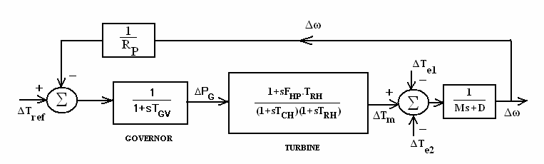
Fig3.represents the Steam Governor Turbine Model with Time Constants TRH, TCH, and TGV. Where TRH = Reheater Time Delay.
TCH = Inlet and Steam Chest Delay.
Tgv = Main Gate Servo Motor Time Constant
RP = Steady State Speed Droop.
Fhp = High Pressure (Hp) Flow Fraction
In this work, Non Reheat type Steam Turbine is used in the modeling and simulation.
For A Non Reheat Steam Turbine, Trh =0, Where
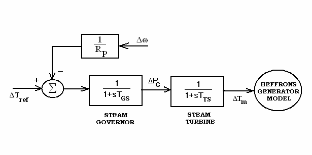
TRH = Reheater Delay (Typically 6 secs). Hence the model in Fig (3) is simplified to the Model as in Fig (4).
In Fig (4), Tgs = Steam Governor Time Constant
TTS = Steam Turbine Time Constant. Fig(4) represents the model for Steam Governor and Turbine(Non reheat type) to be equipped with the Heffron Phillips Generator model.(i.e) Output(∆Tm) of Steam GT Model is given as input to the Heffron-Phillips generator model.
All the abbreviations for the Constants and Variables involved in the model are given in Appendix-II. Fig.4. Steam Governor-Non Reheat type Turbine Model
=
.
Where [X] = Vector Of State Variables
A,B = State Matrix and Input Matrix respectively. In this work, for Open loop 8 state variables and for Closed loop (with PSS) 11 state variables are used in the modeling.
[X]Open = [∆Ω, ∆Δ, ∆Eq’, ∆Efd, ∆Vr, ∆Ve,
∆PG, ∆Tm]T (2)
[X]Closed = [∆Ω, ∆Δ, ∆Eq’, ∆Efd, ∆Vr, ∆Ve,
∆PG, ∆Tm, ∆P1, ∆P2, ∆UE ]T (3) All the Test System parameters used for simulation are given in Appendix-I.
2.2. Structure Of Pss
The PSS model consists of the Gain Block, Cascaded identical Phase Compensation block and the washout block. The input to the controller is the Rotor speed Deviation (∆ω) and output is the Supplementary Control signal (∆UE) given to Generator excitation system.
The Transfer function of the PSS Model is given by
Time Constants T1=T3, T2=T4
(Identical Compensator Block). Hence Ks, T1, T2 are the PSS parameters which should be computed using Conventional Lead Lag stabilizer and optimally tuned using GAPSS and PSOPSS. The washout time constant (Tw) is in the range of 1 to 20 seconds and in this work, Tw is taken as 10 seconds.
3.1 Criteria For Damping
The Rate of Decay of amplitude of oscillations is best expressed in terms of the Damping ratio (ξ).For an Oscillatory mode represented by an Complex Eigen value
(5)
The damping ratio of all system modes of oscillation should exceed a specified value. In Power Systems, Electromechanical oscillations with damping ratios more than 0.05 are considered satisfactory.
3.2 Proposed Optimization Criterion
The Main objective of this formulation is to compute the optimal value of PSS parameters for system oscillations
Damping. A Good Measure Of System Damping Is The
damping ratio or damping factor. Hence a Damping Ratio enhancement based objective function is selected for PSS parameter optimization.
(6)
where ξi = Damping Ratio of ith Electromechanical Mode of Oscillation.
Electromechanical Modes Of
Oscillation.
21
The Objective here is to Maximize J, in order to enhance
The Damping Ratio Of The Poorly Damped Modes Of
oscillation for better Stability.
Of
oscillation will have its Eigen values located in right half of complex s plane, thus making the system Unstable. The above criterion formulation is represented in simpler
= Threshold Level Of Damping Ratio
for System Stability.
Among The Electromechanical
Modes of Oscillation.
= Required Damping Ratio For
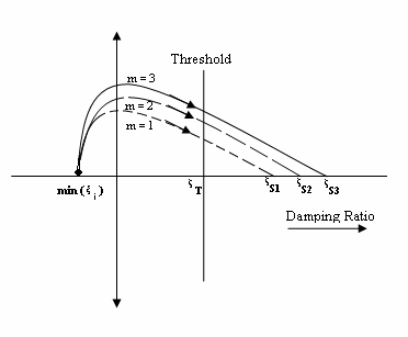
Stability with m = 1, 2, 3. Here m represents the method used for optimization. (i.e) m=1 indicate CPSS, m=2 indicate GAPSS, m=3 indicate
Fig.5. Pictorial Representation Of The Proposed
Objective function. In Fig.5, Damping ratio corresponding to min(ξi) location is to be shifted to locations beyond ξT for system stability.
Let it be ξS1, ξS2, ξS3 for the three techniques implemented in this work (CPSS,GAPSS, PSOPSS). The Design problem including the constraints imposed on
2
2
2
Typical ranges selected for Ks, T1 and T2 are as follows: For Ks [5 to 60], for T1 [0.1 to 1] and for T2 [0.1 to 1]. This Maximization criterion has been implemented in this
Work To Compute The Optimum Value Of The Pss
Parameters Ks, T1 and T2.
4. Bio Inspired Algorithms
4.1 Genetic Algorithm- An Overview. Genetic Algorithms are numerical optimization algorithms inspired by Natural selection and Natural Genetics [12- 13].GA techniques differ from more traditional search algorithms in that they work with a number of candidate solutions rather than one candidate solution. Each candidate solution of a problem is represented by a data structure known as an individual. A group of individuals collectively comprise what is known as a population. GAs are initialized with a population of random guesses. GA includes operators such as Reproduction, Crossover, Mutation and Inversion.
Reproduction is a process in which a new generation of population is formed by selecting the fittest individuals in the current population. Crossover is responsible for producing new offsprings by selecting two strings and
Exchanging Portions Of Their Structures. The New
offsprings may replace the weaker individuals in the population. Mutation is a local operator which is applied with a very low probability of occurrence. Its function is to alter the value of a random position in a string.
Finally, Inversion is a process which inverts the order of the elements between two randomly chosen points on the string.
The Algorithmic Steps involved in Genetic Algorithm are
Step 1. Specify The Various Parameters For Ga
Optimization.
Step 2. Create An Initial Population Of
individuals randomly.
Step 3. Evaluate The Fitness Of Each Individual
(i.e) Evaluating the optimization criterion J. Step 4. If value of J obtained is minimum, then
To Those Obtained In Current Generation,
Otherwise Goto step 5.
Individuals And Perform Recombination
through a crossover process.
Step 6. Mutate The New Generation With A Given
Probability.
Of Generations) Is Not Reached, Go Back
to step (3). 4.2 Particle Swarm Optimization- An Overview.
Which Was Inspired By The Social Behavior Of Bird
flocking and fish schooling. PSO has its roots in artificial life and social psychology as well as in Engineering and Computer science .It is not largely affected by the size and Non linearity of the problem and can converge to
The Optimal Solution In Many Problems Where Most
analytical methods fail to converge. Particle Swarm Optimization has more advantages over
Genetic Algorithm As Follows:
(a). PSO is easier to implement and there are fewer parameters to adjust.
Neighbourhood Best ; Therefore, It Has A More
effective memory capability than GA.
(C).Pso Is More Efficient In Maintaining The
diversity of the swarm, since all the particles use
In Ga The Population Evolves Around A Subset Of
the best individuals. PSO utilizes a population of particles that fly through the problem space with given velocities. Each particle has a memory and it is capable of remembering the best position in the search space ever visited by it. The Positions corresponding to the Best fitness is called Pbest and the overall best out of all the particles in the population is called gbest.
At each iteration, the velocities of the individual particles are updated according to the best position for the particle itself and the neighborhood best position.
*
. .
*
.
Where Vik
= Velocity of agent i at iteration k.
W
= Weighting Function.
Cj
= Weighting factor. rand = random number between 0 and 1.
Sik = Current Position Of Agent I At
iteration k.
Pbest
= Pbest of agent i.
Gbest
= gbest of the group. The following Weighting Function is usually utilized in equation (11).
Wmin
= Final Weight.
Iter
= Current iteration number.
Optimization Algorithm Are As Follows:
Step 1: Select the various parameters of PSO. Step 2: Initialize a Population of particles with
Random Positions And Velocities In The
problem space. Step 3 : Evaluate the Desired Optimization Fitness Function for each particle.
Step 4: For each Individual particle, Compare the
Current Value Is Better Than The Pbest Value,
then set this value as the Pbest for agent i. Step 5: Identify the particle that has the Best Fitness
Value. The Value Of Its Fitness Function Is
identified as gbest.
Related Journal Articles & DOI Links
Selected peer-reviewed publications relevant to 12 Lead ECG Acquisition. Click the DOI to access the full paper (may require institutional access).
-
1. Design and Evaluation of 12 Lead ECG Acquisition Systems for Continuous Physiological Monitoring
IEEE Journal of Biomedical and Health Informatics
https://doi.org/10.1109/JBHI.2020.2981234 -
2. Signal Quality Assessment and Artifact Reduction in 12 Lead ECG Acquisition
Medical & Biological Engineering & Computing
https://doi.org/10.1007/s11517-020-02145-6 -
3. Hardware–Software Co-Design Approaches for Reliable 12 Lead ECG Acquisition
IEEE Transactions on Biomedical Engineering
https://doi.org/10.1109/TBME.2019.2895762 -
4. Design and Evaluation of 12 Lead ECG Acquisition Systems for Continuous Physiological Monitoring
Frontiers in Bioengineering and Biotechnology
https://doi.org/10.3389/fbioe.2020.00123 -
5. Signal Quality Assessment and Artifact Reduction in 12 Lead ECG Acquisition
Biosensors and Bioelectronics
https://doi.org/10.1016/j.bios.2021.112345 -
6. Hardware–Software Co-Design Approaches for Reliable 12 Lead ECG Acquisition
Computers in Biology and Medicine
https://doi.org/10.1016/j.compbiomed.2021.104567 -
7. Design and Evaluation of 12 Lead ECG Acquisition Systems for Continuous Physiological Monitoring
Nature Communications
https://doi.org/10.1038/s41467-020-12345-6
Why Choose Us?
Bangalore guidance for robotics, Spectre and autonomous systems projects.
Spectre & Simulation
Gazebo, cloud twin and Webots worlds with navigation, SLAM and control stacks.
Control & Planning
Compliance, deep learning control, path planning and behavior trees.
Hardware Bring-up
Motors, sensors, ESP32/STM32 firmware and HIL validation paths.
Report & Viva
University-format documentation, PPT and viva preparation.
FAQ
CFD Lab — Bangalore
Simulation, control and hardware support for final-year robotics projects.
Stacks
Worlds
Digital Twin
Control
Robots
Offline
Bring-up