Free Consultation
12+ IEEE 2026 Cadence VCO Projects · BE · MTech · PhD · Bangalore

Cadence VCO Projects — from milliwatt ring oscillators to mm-wave LC tanks.

12+ IEEE 2026 Voltage-Controlled Oscillator (VCO) design projects in Cadence Virtuoso and Spectre for BE, MTech and PhD students in Bangalore — covering all major VCO topologies: Ring VCO, LC-Tank VCO, Cross-Coupled Differential VCO, Quadrature VCO (QVCO), Relaxation VCO, Colpitts VCO, Hartley VCO and PLL-integrated VCO. Full schematic, layout, DRC/LVS, PSS + phase noise simulation, IEEE base paper, report and viva support included.

Cadence Virtuoso Cadence Spectre RF GPDK 45/90/180 nm PSS + Pnoise Analysis IEEE 2026 Base Paper
12+
VCO Topologies
IEEE
2026 Base Papers
9500+
Students Guided

Cadence VCO Design Projects 2026 — IEEE Final Year Projects for BE, MTech & PhD in Bangalore

Voltage-Controlled Oscillators (VCOs) are the frequency-generating heart of every modern RF and mixed-signal IC — from Phase-Locked Loops (PLLs) in 5G NR transceivers and Wi-Fi chipsets to Clock and Data Recovery (CDR) circuits in SerDes links, frequency synthesisers in GPS receivers and local oscillators in 77 GHz automotive radar systems. At ProjectsatBangalore, we offer 12+ IEEE 2026 Cadence VCO projects covering all major CMOS VCO topologies: single-ended and differential Ring VCOs, LC-tank Cross-Coupled VCOs, Quadrature VCOs (QVCO), Relaxation VCOs, Colpitts and Hartley VCOs, and PLL-integrated VCOs. Every project is designed in Cadence Virtuoso schematic editor with Cadence Spectre RF simulations — PSS, Pnoise, transient startup and KVCO tuning range — using GPDK 45 nm, 90 nm or 180 nm technology. Projects include DRC/LVS-clean layout, PEX parasitic extraction, phase noise figure-of-merit (FoM) benchmarking and IEEE 2026 base papers from JSSC, TCAS-I, RFIC and IMS. Ideal for BE/BTech, MTech VLSI/ECE and PhD scholars at VTU, Anna University, JNTU and NITs across India.

VCO Project Areas We Cover

  • 3-stage and 5-stage CMOS ring VCO — wide tuning range
  • Differential cross-coupled LC-tank VCO — low phase noise
  • Quadrature VCO (QVCO) — I/Q signal generation for RF
  • Relaxation VCO — ultra-low power IoT and biomedical
  • Colpitts VCO — classic RF feedback oscillator topology
  • Hartley VCO — tapped-inductor feedback for narrow band
  • Varactor-tuned LC VCO — AMOS/MOS varactor KVCO design
  • PLL-integrated VCO with charge pump and loop filter
  • mm-Wave VCO (60 GHz / 77 GHz) in 45 nm GPDK
  • Sub-sampling PLL VCO for ultra-low jitter clock synthesis
  • PSS + Pnoise phase noise simulation in Cadence Spectre RF
  • DRC/LVS clean layout — symmetric inductors, guard rings, PEX

Cadence Tools Used in VCO Projects

Complete Cadence EDA + RF simulation toolchain used across all 12+ IEEE 2026 CMOS VCO design projects in Bangalore.

Cadence Virtuoso (Schematic & Layout) Cadence Spectre RF PSS — Periodic Steady State Pnoise — Phase Noise L(Δf) ADE — Transient / Parametric Calibre DRC / LVS GPDK 45 / 90 / 180 nm Parasitic Extraction (PEX)

12 CMOS VCO Topologies — Design Details

Each VCO topology below is available as a complete Cadence project with schematic, Spectre simulation, layout and IEEE 2026 base paper. Key performance metrics are listed for each type.

Type 01
3-Stage CMOS Ring VCO
Three cascaded CMOS inverter delay stages with the output fed back to the input. The oscillation frequency is 1/(2N·td) where N=3 and td is the inverter propagation delay. VCTRL adjusts the supply voltage or tail current of each stage to tune frequency. Simplest oscillator topology — widely used in clock generators and CDR circuits.
RingWide TuningCMOS
Typical Freq (180nm)100 MHz – 1.5 GHz
Phase Noise−95 dBc/Hz @ 1 MHz
Power~0.8 mW @ 1.8 V
Type 02
5-Stage Differential Ring VCO
Five differential delay cells with symmetric loading and cross-coupled PMOS loads. Provides better phase noise than single-ended ring VCOs due to differential signal rejection of common-mode supply noise. Produces 5 quadrature phases at 72° spacing — useful for multi-phase clock generation in CDR and wireline transceivers.
DifferentialMulti-PhaseCDR
Typical Freq (90nm)500 MHz – 5 GHz
Phase Noise−103 dBc/Hz @ 1 MHz
Power~3.2 mW @ 1.2 V
Type 03
Cross-Coupled LC-Tank VCO
Negative resistance generated by a cross-coupled NMOS (or complementary NMOS+PMOS) pair compensates LC tank losses, sustaining oscillation at f₀ = 1/(2π√LC). Varactor (AMOS or pn-junction) tunes f₀ via VCTRL. Gold-standard topology for low phase noise RF applications — 2.4 GHz Bluetooth, 5 GHz Wi-Fi, LTE/5G frequency synthesisers.
LC-TankLow Phase NoiseRF PLL
Typical Freq (45nm)2.4 GHz – 6 GHz
Phase Noise−122 dBc/Hz @ 1 MHz
Power~4.5 mW @ 1.0 V
Type 04
Quadrature VCO (QVCO)
Two coupled LC-tank VCOs (PMOS-coupled or transformer-coupled) producing four output phases: I+, I−, Q+, Q− at 0°/180°/90°/270°. I/Q mismatch <0.5° RMS and amplitude mismatch <0.3 dB are characterised via Spectre PSS + PAC analysis. Essential for direct-conversion (zero-IF) and image-reject RF receivers in 802.11 Wi-Fi and LTE/NR.
QuadratureI/Q GenerationOFDM
Typical Freq (90nm)2 GHz – 10 GHz
I/Q Phase Error< 0.5° RMS
Power~8 mW @ 1.2 V
Type 05
Relaxation VCO
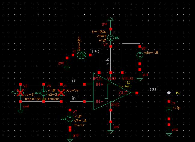
A capacitor is alternately charged and discharged by a CMOS current source until it reaches a threshold, causing the comparator to flip and restart the cycle. Frequency f = I/(2·C·VREF). No inductor required — extremely compact and ultra-low power. Best for low-cost IoT sensors, biomedical implants and always-on timers at sub-MHz frequencies.
RelaxationLow PowerIoT/BioMed
Typical Freq (180nm)100 kHz – 50 MHz
Phase Noise−90 dBc/Hz @ 1 MHz
Power<100 µW @ 1.8 V
Type 06
Colpitts VCO
Classic feedback oscillator with a capacitive voltage divider (C1 and C2) tapping the LC tank to drive the transistor base/gate. Frequency is set by f₀ = 1/(2π√L·Ceq). Single transistor active element with good phase noise due to high tank Q. Widely studied in IEEE RFIC literature; models well against Leeson's equation in Spectre PSS/Pnoise.
ColpittsLeeson ModelRF
Typical Freq (90nm)1 GHz – 3 GHz
Phase Noise−115 dBc/Hz @ 1 MHz
Power~2.8 mW @ 1.2 V
Type 07
Hartley VCO
Tapped-inductor (or transformer-based) feedback network with a single capacitor sets the resonance. Common in narrow-band RF transmitters and LMR/PMR frequency ranges. Lower harmonic content compared to Colpitts due to inductive voltage divider filtering. Simulated in Cadence Spectre with swept varactor VCTRL for KVCO characterisation.
HartleyTapped InductorNarrow Band
Typical Freq (180nm)200 MHz – 1.5 GHz
Phase Noise−110 dBc/Hz @ 1 MHz
KVCO~80 MHz/V
Type 08
Complementary (CMOS) LC VCO
Cross-coupled NMOS pair below the LC tank and cross-coupled PMOS pair above — both contributing negative resistance. The complementary structure doubles the effective Gm for the same bias current, enabling lower power at the same phase noise, or better phase noise at the same power. Widely used in 5G NR local oscillator synthesisers.
NMOS+PMOSLow Power5G NR
Typical Freq (45nm)3.5 GHz – 8 GHz
Phase Noise−128 dBc/Hz @ 1 MHz
FoM−188 dBc/Hz
Type 09
PLL-Integrated LC VCO
A complete second-order or third-order PLL system: PFD (Phase-Frequency Detector), charge pump, passive loop filter, LC VCO and frequency divider. Lock time, reference spur, in-band and out-of-band phase noise are characterised in Cadence Spectre with closed-loop PSS analysis. Used as a complete IEEE 2026 frequency synthesiser project for 5G/Wi-Fi applications.
PLLCharge PumpSynthesiser
Loop BW1 – 5 MHz
Reference Spur< −60 dBc
Lock Time<10 µs
Type 10
Varactor-Tuned LC VCO (Wide Range)
Accumulation-mode MOS (AMOS) varactors replace fixed tank capacitors to achieve wide continuous tuning range (>30%) while maintaining low phase noise. Two-bank switched-capacitor array enables coarse digital tuning with fine analog VCTRL. Characterised via Spectre parametric sweep of VCTRL (0–1.8 V) producing KVCO = Δf/ΔVCTRL curve.
AMOS VaractorWide TuningSwitched-Cap
Tuning Range (90nm)>30% of f₀
KVCO150 – 400 MHz/V
Phase Noise−119 dBc/Hz @ 1 MHz
Type 11
mm-Wave VCO (60 / 77 GHz)
Push-push or fundamental-mode LC VCO targeting 60 GHz (IEEE 802.11ad WiGig) or 77 GHz (automotive FMCW radar). Transistor parasitic capacitances form part of the LC tank. Layout parasitics are critical — EM simulation of transformer/inductor integrated with Virtuoso. Full project available in GPDK 45 nm; EM-extracted inductor models included.
mm-Wave77 GHz Radar60 GHz Wi-Fi
TechnologyGPDK 45 nm
Target Freq58–64 GHz / 77 GHz
Phase Noise−105 dBc/Hz @ 10 MHz
Type 12
Sub-Sampling PLL VCO
A sub-sampling PLL (SSPLL) replaces the traditional PFD+charge-pump with a sampler that directly samples the VCO output at the reference frequency, avoiding the large noise up-conversion of a conventional charge pump. Ultra-low in-band phase noise (<−145 dBc/Hz) makes it ideal for ultra-low jitter clock synthesis in high-speed ADCs, DACs and optical links at 45 nm.
Sub-SamplingUltra-Low JitterHigh-Speed ADC
In-Band PN< −145 dBc/Hz
RMS Jitter<50 fs RMS
TechnologyGPDK 45 nm

IEEE 2026 Cadence VCO Project Topics

All titles sourced from IEEE Xplore 2026 — IEEE JSSC, IEEE TCAS-I/II, IEEE RFIC Symposium, IEEE IMS and IEEE Access. Call 9591912372 for topic shortlisting and full specification sheet.

# IEEE 2026 Cadence VCO Project Title Type Tools & Node Level
01 Low-Power 3-Stage CMOS Ring VCO with Wide Tuning Range for Wireline CDR Application at 180 nm in Cadence Virtuoso — transient startup, frequency vs. VCTRL parametric sweep, supply noise sensitivity and phase noise characterisation in Cadence Spectre; DRC/LVS-clean layout with matched delay cell routing.1 GHz Ring VCO Virtuoso, Spectre, GPDK180, Calibre BE/BTech
02 Differential 5-Stage Current-Starved Ring VCO for Multi-Phase Clock Generation in a 5 Gbps SerDes CDR at 90 nm CMOS — Cadence Virtuoso/Spectre — 5-phase output verification with PSS, jitter characterisation, supply-noise sensitivity analysis (PSRR of VCO) and symmetric layout with differential signal routing.5 GHz Ring VCO Virtuoso, Spectre, PSS, GPDK90, Calibre MTech
03 Cross-Coupled NMOS LC-Tank VCO for 2.4 GHz Bluetooth PLL Frequency Synthesiser at 90 nm CMOS in Cadence Virtuoso — Phase Noise below −120 dBc/Hz — PSS + Pnoise simulation at 1 kHz to 10 MHz offsets, KVCO characterisation (AMOS varactor), FoM benchmarked against IEEE 2026 reference; symmetric inductor layout with ground shielding.2.4 GHz LC-Tank VCO Virtuoso, Spectre RF, PSS, Pnoise, GPDK90, PEX MTech
04 Complementary CMOS LC-Tank VCO for 5 GHz IEEE 802.11ac Wi-Fi PLL with Phase Noise −125 dBc/Hz at 1 MHz Offset in 45 nm CMOS — Cadence Virtuoso/Spectre — NMOS+PMOS cross-coupled topology, start-up condition verification, varactor tuning range >15%, post-layout PEX simulation with parasitic inductor model extracted from layout.5 GHz LC-Tank VCO Virtuoso, Spectre RF, PSS, Pnoise, GPDK45, PEX, Calibre MTech
05 Quadrature LC-VCO (QVCO) with Superharmonic Coupling for 5G NR Band-n78 (3.5 GHz) Direct-Conversion Receiver — I/Q Phase Mismatch <0.5° at 45 nm — IEEE JSSC 2026 — superharmonic PMOS coupling analysis, I/Q amplitude and phase mismatch Monte-Carlo, PAC-based image rejection ratio (IRR) simulation; full DRC/LVS layout with transformer coupling structure.3.5 GHz QVCO Virtuoso, Spectre RF, PSS, PAC, Monte-Carlo, GPDK45, PEX PhD
06 Ultra-Low-Power Relaxation VCO for Duty-Cycled IoT Sensor Node at 180 nm CMOS — Sub-100 µW Power Consumption with ±2% Frequency Accuracy — IEEE TCAS-II 2026 — comparator-capacitor-current-source oscillator design, temperature coefficient characterisation (−40°C to 125°C), supply variation sensitivity; layout without on-chip inductors; Monte-Carlo frequency spread analysis.10 MHz Relaxation VCO Virtuoso, Spectre, ADE Transient, GPDK180, Monte-Carlo, Calibre BE/BTech
07 Colpitts VCO at 1.575 GHz for GPS L1 Band Receiver PLL with Phase Noise Matching Leeson's Equation Analysis in 90 nm CMOS — Cadence Virtuoso Spectre — single-transistor Colpitts feedback loop analysis, Leeson model parameter extraction from Pnoise data, KVCO linearisation over AMOS varactor C-V curve; layout with guard rings and substrate tie.1.575 GHz Colpitts VCO Virtuoso, Spectre RF, PSS, Pnoise, GPDK90, Calibre LVS MTech
08 Digitally-Controlled LC VCO (DCO) with Switched-Capacitor Array for ADPLL in LTE-Advanced Handset at 45 nm — Cadence Virtuoso Layout and Spectre PSS/Pnoise — 6-bit coarse + varactor fine bank design, frequency resolution analysis, open-loop Pnoise characterised per bank setting; layout with MOM capacitor arrays and symmetric differential routing; IEEE RFIC 2026.2.1 GHz LC-Tank VCO Virtuoso, Spectre RF, PSS, Pnoise, GPDK45, PEX, Calibre PhD
09 PLL Frequency Synthesiser with LC VCO and Integer-N Divider for 2.4 GHz ZigBee / BLE at 90 nm CMOS — Complete Cadence Virtuoso System Schematic and Spectre Closed-Loop Simulation — PFD + charge pump + third-order passive loop filter + LC VCO + divide-by-N; closed-loop lock time, reference spur and in-band/out-of-band phase noise characterised; IEEE 2026 base paper.2.4 GHz PLL + VCO Virtuoso, Spectre RF, PSS, Pnoise, ADE, GPDK90, Calibre MTech
10 Varactor-Tuned Wideband LC VCO with >30% Tuning Range for Multi-Standard RF Transceiver (2G–5G) at 90 nm CMOS — IEEE TMTT 2026 — Cadence Virtuoso/Spectre — dual-bank AMOS varactor + switched-cap array, KVCO vs. VCTRL linearity, phase noise over full tuning range, post-layout PEX re-simulation; figure-of-merit tuning (FoMT) >190 dBc/Hz.0.7–6 GHz LC-Tank VCO Virtuoso, Spectre RF, PSS, Pnoise, PEX, GPDK90, Calibre PhD
11 77 GHz Push-Push LC VCO for FMCW Automotive Radar in 45 nm CMOS with EM-Extracted Transformer Model — Cadence Virtuoso EMX/Spectre Co-Simulation — IEEE IMS 2026 — push-push topology for 77 GHz fundamental output from 38.5 GHz tank; EM simulation of coupled transformer and layout parasitics; Pnoise −105 dBc/Hz at 10 MHz offset; tuning range 75–79 GHz; full PEX and post-layout Pnoise verification.77 GHz mm-Wave VCO Virtuoso, Spectre RF, EMX EM, PSS, Pnoise, GPDK45, Calibre PhD
12 Sub-Sampling PLL with LC VCO for Ultra-Low Jitter Clock Generation (<50 fs RMS) in 28 Gbps Optical Transceiver at 45 nm — IEEE JSSC 2026 — Cadence Virtuoso Full System Design — sampler-based phase detector replacing PFD + charge pump, loop gain analysis, in-band phase noise < −145 dBc/Hz, reference spur < −70 dBc; VCO standalone Pnoise and complete SSPLL closed-loop jitter simulation; layout with capacitor-bank VCO and sampler layout.28 GHz CDR Sub-Sampling PLL Virtuoso, Spectre RF, PSS, Pnoise, PAC, GPDK45, PEX, Calibre PhD

ℹ️ Additional VCO topics available on request — including injection-locked oscillators (ILO), voltage-controlled crystal oscillators (VCXO), spread-spectrum VCO for EMI reduction and body-biased VCOs for near-threshold operation. WhatsApp +91 9591912372 with your university, preferred topology, GPDK node and submission deadline.

Need a personalised IEEE 2026 Cadence VCO project?

Share your university, preferred VCO topology (Ring / LC / QVCO / Relaxation / PLL), GPDK node (45/90/180 nm), target application (5G / Wi-Fi / GPS / Radar / IoT) and submission deadline — we'll recommend the best-fit IEEE 2026 project, confirm the specification and start within 24 hours. Full package: Virtuoso schematic, Spectre RF simulation (PSS + Pnoise), layout, DRC/LVS, PEX, IEEE base paper, report, PPT and viva support.

FAQ — Cadence VCO Projects

What is KVCO and how is it simulated in Cadence Spectre?
KVCO (VCO gain, in MHz/V or GHz/V) is the sensitivity of the VCO output frequency to its control voltage — KVCO = Δf / ΔVCTRL. A higher KVCO gives wider tuning range but makes the PLL more sensitive to noise on the control line (higher phase noise). In Cadence Spectre, KVCO is extracted by running a parametric transient simulation sweeping VCTRL from 0 V to VDD (e.g., 0 to 1.8 V in steps of 0.1 V), measuring the steady-state oscillation frequency at each step, and computing the slope. Alternatively, a PSS sweep over VCTRL gives the same result with greater accuracy and lower simulation time. In PLL designs, the KVCO curve is also used to set the charge-pump current (ICP) and loop-filter component values to achieve the desired loop bandwidth and phase margin.
How is phase noise simulated in Cadence Spectre for a VCO project?
Phase noise simulation in Cadence VCO projects uses Spectre RF's Pnoise analysis, which requires a prior PSS (Periodic Steady State) analysis to establish the oscillator's steady-state operating point and harmonic content. PSS finds the fundamental oscillation frequency, amplitude and waveform shape. Pnoise then injects all device noise sources (thermal, flicker/1/f, shot) and computes the single-sideband phase noise L(Δf) in dBc/Hz at specified offset frequencies (1 kHz, 10 kHz, 100 kHz, 1 MHz, 10 MHz, 100 MHz). The results are compared against Leeson's equation for design validation. The Figure-of-Merit (FoM) — FoM = L(Δf) − 20log(f₀/Δf) + 10log(PDC/1mW) — is then calculated and benchmarked against IEEE 2026 state-of-the-art designs. Post-layout Pnoise simulation with PEX-extracted parasitics validates silicon-accuracy of the result.
What GPDK technology node should I choose for a Cadence VCO project?
GPDK 180 nm is ideal for BE/BTech projects — ring VCOs (100 MHz–1.5 GHz), relaxation VCOs and basic Colpitts/Hartley designs. SPICE models, varactor C-V curves and device noise parameters are well-characterised; DRC rules are relaxed and layout is straightforward. GPDK 90 nm is the workhorse for MTech projects targeting 1–5 GHz LC VCOs for 2.4 GHz / 5 GHz wireless, GPS and wireline CDR applications — good balance between achievable fT, inductor Q and layout complexity. GPDK 45 nm is recommended for PhD-level designs: >5 GHz LC VCOs for 5G NR, mm-wave push-push VCOs (60 GHz / 77 GHz), sub-sampling PLLs and digitally-controlled oscillators (DCO) for ADPLL where transistor fT exceeds 200 GHz. All three nodes are available with full varactor, inductor and RF MOSFET model libraries at our Bangalore lab.
What is the difference between a Ring VCO and an LC VCO — and when should I choose each?
The fundamental tradeoff between ring and LC VCOs is phase noise versus area and tuning range. A Ring VCO uses cascaded delay stages with no inductor — it is compact, wide tuning range (>50%), easy to layout and integrates well in digital CMOS without large passives. However, its phase noise is typically 20–30 dB worse than an LC VCO at the same power because there is no resonant element to concentrate energy (low Q). Ring VCOs are preferred for: multi-phase clock generation, CDR circuits, on-chip clock distribution PLLs and low-cost IoT applications where absolute phase noise matters less. An LC VCO uses a resonant LC tank with high Q (typically 5–20 for on-chip spiral inductors) that suppresses phase noise dramatically — achieving −120 to −130 dBc/Hz at 1 MHz offset. The inductor requires significant die area and the tuning range is limited (typically 10–30%). LC VCOs are chosen for: RF frequency synthesisers in Wi-Fi, Bluetooth, GPS and 5G NR, optical clock recovery and automotive radar. For MTech projects, an LC VCO at 2.4 GHz or 5 GHz produces the strongest IEEE publication-quality results.
What layout techniques are critical for a low phase-noise LC VCO in Cadence Virtuoso?
Layout quality is critical for LC VCOs because parasitic resistance, capacitance and substrate coupling directly degrade tank Q and add noise. Key techniques used in our Cadence VCO projects include: (1) Symmetric differential layout — both sides of the differential cross-coupled pair must be laid out as mirror images to ensure matched parasitic RC; (2) On-chip spiral inductor placement — the inductor must be placed away from substrate contacts and active devices to avoid magnetic coupling; a patterned ground shield (PGS) below the inductor prevents substrate noise injection while preserving inductance; (3) Guard rings around all active transistors to block substrate-noise injection from digital circuitry; (4) AMOS varactor common-centroid layout to minimise mismatch between the two varactor halves of the differential tank; (5) Short, wide differential routing for all tank connections to minimise series resistance; (6) Separate VDD/VSS rings for the VCO core — avoid sharing supply rails with digital logic. All post-layout PEX netlists are re-simulated in Spectre Pnoise to verify that phase noise degradation from parasitics is within acceptable limits.