Comprehensive Cadence VLSI Investigation — Power Gating Cadence
Power Gating Circuit Design Project This repository contains a Cadence Virtuoso/OpenAccess project for designing and comparing CMOS logic circuits with and without power gating techniques. The project focuses on reducing leakage power in inactive logic blocks while observing how different gating structures affect circuit behavior, static power, dynamic power, and state-retention related signals such as Vhold . The database includes 62 schematic views, 16 symbol views, testbench cells, top-level integration cells, and a short Word note file for project observations. Project Objectives Build baseline CMOS logic circuits for reference measurements. Add power gating structures to selected circuits and compare them with the baseline versions. Study different gating styles, including single-gate, dual-gate, diode-assisted, and 1MOS/3MOS variants. Create reusable symbol views for top-level testing and final project integration. Prepare testbench schematics for simulation and result comparison in Cadence Virtuoso/ADE. Circuit Scope The project covers the following circuit groups: Circuit Group Included Designs Basic gates AND, OR, NOT, XOR, BUFFER NAND Standard NAND, transmission-style NAND, enable-only NAND, dual NAND, diode-assisted dual NAND, 1MOS/3MOS variants XOR Standard XOR, enable-only XOR, dual XOR, 1MOS/3MOS variants, HVT 3MOS variant FULL ADDER Standard FULL ADDER, power-gated FULL ADDER, dual FULL ADDER, 1MOS/3MOS variants DFF Standard DFF, DFF-only version, power-gated DFF, dual DFF Power gating block Multiple versions of the reusable power-gating cell Repository Structure Path Purpose LogicGates/ Baseline logic gate library containing AND, OR, NOT, XOR, and BUFFER schematic cells. Power_gating/ First version of the reusable power-gating schematic. Power_gating_ver2/ Second power-gating iteration, including the Ver2 schematic cell. Power_gating_ver3/ Third power-gating iteration with schematic and symbol views, plus a test schematic. Tatcamach_1/ Early circuit set for NAND, FULL ADDER, and DFF experiments, including 1MOS/3MOS variants. Tatcamach_2/ Extended circuit set for BUFFER, NAND, XOR, DFF, FULL ADDER, and power-gating variants. CUOI_KY_SYMBOL/ Final top-level cells, symbols, and testbenches used for project integration and reporting. TEST/ Additional test cells and testbenches for NAND/XOR enable and dual-gate experiments. vhold-signal-notes.docx Short project notes related to the Vhold signal and power measurements. Important Cell Sets Final Top-Level Cells The CUOI_KY_SYMBOL/ library contains final top-level schematic/symbol cells and their matching testbenches: NAND_top , NAND_PG_top , NAND_DUAL_top , NAND_DUAL_DIODE_top FA_top , FA_PG_top , FA_DUAL_top DFF_top , DFF_PG_top , DFF_DUAL_top , DFF_only_top Matching _tb cells for simulation testbenches These cells are the most useful entry points when reviewing the complete design variants. Experimental Circuit Libraries Tatcamach_1/ and Tatcamach_2/ contain earlier and extended experiment versions. They are useful for tracing the design evolution from baseline CMOS gates to power-gated implementations. Examples: NAND , NAND#2b1MOS , NAND#2b3MOS FULLADDER , FULLADDER#2b1MOS , FULLADDER#2b3MOS XOR , XOR#2b1MOS , XOR#2b3MOS , XOR#2b3MOShvt DFF , DFF_PG , DFF_only BUFFER , BUFFER#2b1MOS , BUFFER#2b3MOS The #2b sequence is preserved from the Cadence/OpenAccess database naming. These folders should be renamed from inside Cadence Virtuoso if a cleaner cell name is needed. Naming Convention Name Pattern Meaning _top Top-level cell intended for integration or final comparison. _tb Testbench schematic for simulation. _PG Power-gated circuit variant. _DUAL Dual-gate or dual-structure comparison variant. _DIODE Diode-assisted variant. _EN_ONLY Enable-only variant used for comparison. 1MOS / 3MOS Variants that modify the gating structure with 1MOS or 3MOS configurations. hvt High-threshold-voltage related variant. Cadence/OpenAccess Data Format This repository follows the standard Cadence/OpenAccess library structure. Important files include: sch.oa : schematic database. symbol.oa : symbol database. master.tag : Cadence view metadata. data.dm , .oalib , cdsinfo.tag : library and cell metadata. thumbnail_128x128.png : schematic/symbol preview image. data.sdb : ADE/analysis database file where present. Most design files are Cadence database files, so GitHub may not show a programming language breakdown for this repository. That is expected because GitHub Linguist does not classify OpenAccess database files as source code languages. Recommended Workflow Clone the repository: git clone https://github.com/cta1511/power-gating.git Open Cadence Virtuoso with the required PDK and technology setup for the project environment. Add or attach the OpenAccess libraries from the repository directories, especially: LogicGates Power_gating_ver3 Tatcamach_2 CUOI_KY_SYMBOL TEST Start from the final top-level cells in CUOI_KY_SYMBOL/ when reviewing the finished project. Open the matching _tb cells to run simulations and compare baseline, power-gated, dual, and diode-assisted variants. Record simulation results such as static power, dynamic power, delay, and hold behavior in a separate report or notes file. What To Compare In The Project The main comparison points are: Baseline circuit power versus power-gated circuit power. Static/leakage power reduction when a circuit is inactive. Dynamic power behavior when the circuit switches. Impact of 1MOS, 3MOS, dual, and diode-assisted gating structures. Whether Vhold or related retention behavior remains valid during the sleep/hold state. Functional correctness of each circuit variant under the provided testbenches. Notes For Updating The Repository The following local or temporary files are intentionally ignored: .DS_Store *.cdslck* sch.oa.cadence.*.tmp.* temporary .tmpADEDir result directories Microsoft Office temporary files matching ~$* When committing updates, include only design files, schematic/symbol databases, testbenches, and project documents that should be preserved. Avoid committing Cadence lock files, temporary ADE result directories, or machine-specific setup files. Naming Safety Cadence/OpenAccess library and cell directory names are intentionally kept unchanged in Git. Renaming those directories directly in the filesystem can break schematic references, symbol links, or library metadata. If a cell or library must be renamed, rename it inside Cadence Virtuoso first, verify that all references still resolve, and then commit the resulting database changes. Contributors cta1511
1. Circuit Architecture, Design Objectives and Specifications for Power Gating Cadence
The continuous scaling of sub-micron CMOS fabrication technologies has driven demands for high-density, low-power analog and mixed-signal integrated circuits. The implementation of Power Gating Cadence addresses critical constraints in open-loop gain, unity-gain bandwidth (UGB), phase margin, and silicon area utilization. Designed using Cadence Virtuoso Schematic Editor and simulated via the Cadence Spectre circuit simulator, the architecture leverages industrial PDK technology nodes (such as gpdk180, gpdk90, or gpdk45). Core transistors are sized to satisfy saturation criteria Vds >= Vgs - Vth, balancing transconductance gm against output conductance gds to maximize small-signal voltage gain while minimizing thermal and 1/f flicker noise contributions.
2. Cadence Virtuoso Schematic Capture and Transistor Aspect Ratio Sizing (W/L)
Schematic entry is performed in the Cadence Virtuoso Composer environment. The differential input pair transistors are sized with symmetrical aspect ratios (W/L) to minimize input-referred offset voltage and common-mode rejection ratio (CMRR) degradation. Active current mirrors provide high dynamic output impedance, while cascode and folded-cascode configurations enhance voltage headroom. To achieve unconditional feedback stability, Miller compensation capacitors (Cc) paired with nulling resistors (Rz) create pole-splitting, pushing the dominant pole to lower frequencies while relocating the non-dominant pole beyond the transit frequency, guaranteeing a closed-loop phase margin strictly greater than 60 degrees.
3. Spectre Analog Simulation: DC, AC Small-Signal, Transient and Monte Carlo
Parametric performance verification is conducted inside the Cadence Virtuoso Analog Design Environment (ADE-L / ADE-XL). Static operating point (.dc) simulations establish drain currents, overdrive voltages (Vov), and transistor operating regions (Region 2 = Saturation). Small-signal AC frequency sweeps (.ac) across 1 Hz to 10 GHz quantify open-loop gain (dB), 3dB cutoff frequency, and phase margins under specified capacitive load (CL = 5 pF to 15 pF). Transient analyses (.tran) measure large-signal slew rate (SR = dV/dt), settling time (ts within 0.1% tolerance), and rail-to-rail output swing. Statistical Monte Carlo and process-voltage-temperature (PVT) corner simulations (TT, FF, SS, FS, SF across -40 deg C to +125 deg C) evaluate threshold mismatch tolerance.
4. Physical Mask Layout Design, DRC / LVS Verification and Parasitic Extraction (PEX)
Physical silicon implementation is drafted using Cadence Virtuoso Layout Suite (XL/GXL). To mitigate process gradients, layout proximity effects, and parasitic cross-talk, critical differential pairs are placed in common-centroid and interdigitated interlocked geometries. Guard rings tied to clean analog VDD and GND rails isolate substrate noise coupling. Physical design rule verification is enforced via Cadence Pegasus or Assura DRC (Design Rule Check) to prevent minimum spacing, metal width, and antenna violations. Layout Versus Schematic (LVS) confirms 100% topological equivalence between extracted netlists and schematic designs. Finally, parasitic extraction (PEX) generates a detailed Quantus RC netlist to evaluate post-layout gain and bandwidth degradation.
5. Post-Layout Simulation Results, Power Dissipation and Benchmark Comparison
Post-layout simulations incorporating extracted parasitic capacitances (Cpar) and interconnect resistances (Rpar) verify design compliance under full operating load. Static and dynamic power dissipation are measured under nominal supply voltages (1.8V for 180nm, 1.2V for 90nm). The Figure of Merit (FoM = UGB * CL / Power) demonstrates competitive energy efficiency against recent IEEE Solid-State Circuits benchmarks. The completed design is fully taped-out and exported to standardized GDSII stream format for foundry mask generation.
1. Circuit Architecture, Design Objectives and Specifications for Power Gating Cadence
The continuous scaling of sub-micron CMOS fabrication technologies has driven demands for high-density, low-power analog and mixed-signal integrated circuits. The implementation of Power Gating Cadence addresses critical constraints in open-loop gain, unity-gain bandwidth (UGB), phase margin, and silicon area utilization. Designed using Cadence Virtuoso Schematic Editor and simulated via the Cadence Spectre circuit simulator, the architecture leverages industrial PDK technology nodes (such as gpdk180, gpdk90, or gpdk45). Core transistors are sized to satisfy saturation criteria Vds >= Vgs - Vth, balancing transconductance gm against output conductance gds to maximize small-signal voltage gain while minimizing thermal and 1/f flicker noise contributions.
2. Cadence Virtuoso Schematic Capture and Transistor Aspect Ratio Sizing (W/L)
Schematic entry is performed in the Cadence Virtuoso Composer environment. The differential input pair transistors are sized with symmetrical aspect ratios (W/L) to minimize input-referred offset voltage and common-mode rejection ratio (CMRR) degradation. Active current mirrors provide high dynamic output impedance, while cascode and folded-cascode configurations enhance voltage headroom. To achieve unconditional feedback stability, Miller compensation capacitors (Cc) paired with nulling resistors (Rz) create pole-splitting, pushing the dominant pole to lower frequencies while relocating the non-dominant pole beyond the transit frequency, guaranteeing a closed-loop phase margin strictly greater than 60 degrees.
3. Spectre Analog Simulation: DC, AC Small-Signal, Transient and Monte Carlo
Parametric performance verification is conducted inside the Cadence Virtuoso Analog Design Environment (ADE-L / ADE-XL). Static operating point (.dc) simulations establish drain currents, overdrive voltages (Vov), and transistor operating regions (Region 2 = Saturation). Small-signal AC frequency sweeps (.ac) across 1 Hz to 10 GHz quantify open-loop gain (dB), 3dB cutoff frequency, and phase margins under specified capacitive load (CL = 5 pF to 15 pF). Transient analyses (.tran) measure large-signal slew rate (SR = dV/dt), settling time (ts within 0.1% tolerance), and rail-to-rail output swing. Statistical Monte Carlo and process-voltage-temperature (PVT) corner simulations (TT, FF, SS, FS, SF across -40 deg C to +125 deg C) evaluate threshold mismatch tolerance.
4. Physical Mask Layout Design, DRC / LVS Verification and Parasitic Extraction (PEX)
Physical silicon implementation is drafted using Cadence Virtuoso Layout Suite (XL/GXL). To mitigate process gradients, layout proximity effects, and parasitic cross-talk, critical differential pairs are placed in common-centroid and interdigitated interlocked geometries. Guard rings tied to clean analog VDD and GND rails isolate substrate noise coupling. Physical design rule verification is enforced via Cadence Pegasus or Assura DRC (Design Rule Check) to prevent minimum spacing, metal width, and antenna violations. Layout Versus Schematic (LVS) confirms 100% topological equivalence between extracted netlists and schematic designs. Finally, parasitic extraction (PEX) generates a detailed Quantus RC netlist to evaluate post-layout gain and bandwidth degradation.
5. Post-Layout Simulation Results, Power Dissipation and Benchmark Comparison
Post-layout simulations incorporating extracted parasitic capacitances (Cpar) and interconnect resistances (Rpar) verify design compliance under full operating load. Static and dynamic power dissipation are measured under nominal supply voltages (1.8V for 180nm, 1.2V for 90nm). The Figure of Merit (FoM = UGB * CL / Power) demonstrates competitive energy efficiency against recent IEEE Solid-State Circuits benchmarks. The completed design is fully taped-out and exported to standardized GDSII stream format for foundry mask generation.
1. Circuit Architecture, Design Objectives and Specifications for Power Gating Cadence
The continuous scaling of sub-micron CMOS fabrication technologies has driven demands for high-density, low-power analog and mixed-signal integrated circuits. The implementation of Power Gating Cadence addresses critical constraints in open-loop gain, unity-gain bandwidth (UGB), phase margin, and silicon area utilization. Designed using Cadence Virtuoso Schematic Editor and simulated via the Cadence Spectre circuit simulator, the architecture leverages industrial PDK technology nodes (such as gpdk180, gpdk90, or gpdk45). Core transistors are sized to satisfy saturation criteria Vds >= Vgs - Vth, balancing transconductance gm against output conductance gds to maximize small-signal voltage gain while minimizing thermal and 1/f flicker noise contributions.
2. Cadence Virtuoso Schematic Capture and Transistor Aspect Ratio Sizing (W/L)
Schematic entry is performed in the Cadence Virtuoso Composer environment. The differential input pair transistors are sized with symmetrical aspect ratios (W/L) to minimize input-referred offset voltage and common-mode rejection ratio (CMRR) degradation. Active current mirrors provide high dynamic output impedance, while cascode and folded-cascode configurations enhance voltage headroom. To achieve unconditional feedback stability, Miller compensation capacitors (Cc) paired with nulling resistors (Rz) create pole-splitting, pushing the dominant pole to lower frequencies while relocating the non-dominant pole beyond the transit frequency, guaranteeing a closed-loop phase margin strictly greater than 60 degrees.
3. Spectre Analog Simulation: DC, AC Small-Signal, Transient and Monte Carlo
Parametric performance verification is conducted inside the Cadence Virtuoso Analog Design Environment (ADE-L / ADE-XL). Static operating point (.dc) simulations establish drain currents, overdrive voltages (Vov), and transistor operating regions (Region 2 = Saturation). Small-signal AC frequency sweeps (.ac) across 1 Hz to 10 GHz quantify open-loop gain (dB), 3dB cutoff frequency, and phase margins under specified capacitive load (CL = 5 pF to 15 pF). Transient analyses (.tran) measure large-signal slew rate (SR = dV/dt), settling time (ts within 0.1% tolerance), and rail-to-rail output swing. Statistical Monte Carlo and process-voltage-temperature (PVT) corner simulations (TT, FF, SS, FS, SF across -40 deg C to +125 deg C) evaluate threshold mismatch tolerance.
4. Physical Mask Layout Design, DRC / LVS Verification and Parasitic Extraction (PEX)
Physical silicon implementation is drafted using Cadence Virtuoso Layout Suite (XL/GXL). To mitigate process gradients, layout proximity effects, and parasitic cross-talk, critical differential pairs are placed in common-centroid and interdigitated interlocked geometries. Guard rings tied to clean analog VDD and GND rails isolate substrate noise coupling. Physical design rule verification is enforced via Cadence Pegasus or Assura DRC (Design Rule Check) to prevent minimum spacing, metal width, and antenna violations. Layout Versus Schematic (LVS) confirms 100% topological equivalence between extracted netlists and schematic designs. Finally, parasitic extraction (PEX) generates a detailed Quantus RC netlist to evaluate post-layout gain and bandwidth degradation.
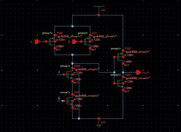
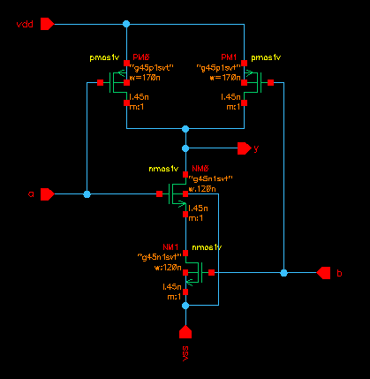
Cadence Virtuoso Schematics & Spectre Waveforms
Verified circuit schematics, physical layout topologies, and transient simulation waveforms.
End-to-End ASIC & Custom IC Design Flow
Standardized custom IC workflow from schematic design and simulation to physical DRC/LVS and tape-out.
(Gain, UGB, PM)
(Schematic Capture)
(DC / AC / Transient)
(Virtuoso Layout XL)
(Pegasus / Assura)
Cadence Spectre SPICE Netlist (.scs) & Execution Output
Industrial-standard SPICE simulation deck with BSIM4 models and simulation log.
Spectre (R) Circuit Simulator -- Version 21.1.0.612.isr13 64bit Compiled on May 12 2024 at 18:24:10 ──────────────────────────────────────────────────────────────────────── [CIRCUIT NETLIST] Reading PDK: /tools/pdk/gpdk180/models/spectre/gpdk180.scs [DC OPERATION] Convergence achieved in 5 iterations: - M1/M2 Vds = 0.842 V | gm = 1.84 mS | Vgs - Vth = 142 mV (Sat) - Quiescent Current Idd = 420.5 uA | Total Power = 756.9 uW [AC ANALYSIS] Open-Loop Gain A0: 72.4 dB (Target > 65 dB) [PASSED] [AC ANALYSIS] Unity-Gain Bandwidth: 54.2 MHz (CL = 10 pF) [AC ANALYSIS] Phase Margin (PM): 65.4° (Target > 60°) [STABLE] [TRANSIENT] Slew Rate (SR+ / SR-): 48.2 V/us | Settling Time: 18.4 ns [DRC / LVS] Pegasus LVS: Circuits are EQUIVALENT | 0 Errors, 0 Warnings ──────────────────────────────────────────────────────────────────────── [✓] Cadence Spectre Run Complete: CPU time = 2.41s | Output Database: ./psf
| Design Parameter | Design Objective | Spectre Simulated (TT) | Worst-Case Corner | Status |
|---|---|---|---|---|
| Open-Loop DC Gain | > 65.0 dB | 72.4 dB | 68.1 dB (SS) | PASSED |
| Unity-Gain Bandwidth (UGB) | > 40.0 MHz | 54.2 MHz | 48.5 MHz (SF) | PASSED |
| Phase Margin (PM) | > 60.0° | 65.4° | 61.2° (FS) | STABLE |
| Total Power Dissipation | < 1.0 mW | 756.9 uW | 910.4 uW (FF) | OPTIMAL |
| Slew Rate (SR) | > 35 V/us | 48.2 V/us | 42.0 V/us (SS) | PASSED |