Comprehensive Cadence VLSI Investigation — Sar ADC Design Cadence
Complete theory, design, schematic, and layout implementation of a CMOS SAR ADC using Cadence Virtuoso.
SAR ADC Design of 8 bit SAR ADC This project presents the complete design, implementation, and analysis of an 8-bit Successive Approximation Register (SAR) Analog-to-Digital Converter (ADC) using Cadence Virtuoso tool. This ADC works on principle of binary search algorithm. The system is composed of four main building blocks: a Sample and Hold (S/H) circuit, a Comparator, a Successive Approximation Register, and an R-2R ladder-based Digital-to-Analog Converter (DAC). The design methodology adopted for this project emphasizes a bottom-up approach, starting with transistor-level schematic design & going upto functional bock level design. For layout we only performed DRC & LVS. we didnt perfrom post layout simulation, PVT analysis etc Specifications of ADC - ADC Type = SAR ADC Resolution = 8 bits Sample Hold clock speed = 100 ns (10Mhz) SAR register clock speed = 11.1111 ns (90MHz) Conversion time = 8 bits * 11.1111 = 88.8888 ns Supply voltage = 3.3v Technology used = 180nm software tools Tool Description Cadence Design Systems provides a wide range of products and services including digital integrated circuit design, functional verification, custom IC design, PCB layout and design, and system design enablement. block diagram of ADC OPAMP we have designed PMOS differential pair OPAMP. it is a 2 stage OPAMP - 1st stage is differential pair amplifier , 2nd stage is CS smplifier. on LHS we have constant current source. OPAMP is fundamental part of our design cuz we will use this OPAMP to further design other 3 analog blocks - SH, DAC, Comparator. we used root force method to do sizing of MOSFETS. OPAMP - MOSFET sizing MOSFET M2 M4 M5 M6 M7 M9 M1 M8 M3 LENGTH 1u 1u 1u 1u 1u 1u 1u TOTAL WIDTH 76.39u 6.65u 10u 14.55u 18.14u 2.46u 71.2u WIDTH OF EACH MULTIPLIER 6.365u 6.65u 2u 2.425u 6.046u 2.46u 5.93u NUMBER OF MULTIPLIER 12 1 5 6 3 1 12 OPAMP circuit diagram OPAMP - inter digitization & segmentation OPAMP - layout OPAMP parameters parameter theoretical value practical value suuply voltage 3.3 v 3.3 v phase margin PM > 60 db 180 - 90 = 86 db power PD < 2 mW (50 + 200 + 200)3.3 = 1.485 mW settling time Ts < 40ns 56.159 ns gain bandwidth product NA 33 MHz open loop gain NA 73.8 dB unity gain frequency NA 28.99 MHz phase angle NA 93.57 degree slew rate NA 4.808 KV/us ADC circuit diagram ADC parameters Parameters This Work Paper [5] Paper [6] Paper [7] Paper [8] Paper [9] Technology Node (nm) 180 180 65 90 40 90 Resolution (Bits) 8 8 14 6 10 10 Sampling Rate (MS/s) 10 100 5000 1 120 1 Supply Voltage (v) 3.3 1.8 1 1 1.2 1.2 Power (uW) 8332 129.8 70 77.26 1040 11.88 ENOB 7 NA NA 5.05 NA NA SNR (dB) 43.76 NA NA 37.34 NA NA SFDR (dB) 50.23 NA NA NA NA NA SNDR (dB) 41.12 NA NA NA 46.9 NA Architecture SAR R-2R Binary weighted capacitive Capacitive Binary weighted resistor NA Capacitive ADC layout layout parameters parameters values core dimensions 370 um * 370 um die dimensions 518 um * 518 um pad dimensions 74 um * 74 um filler pad 74 um * 14.8 um total pads 16 total MOSFET in layout 1250 total resistors in layout 20 total capacitors in layout 21 Team Members @vansh @ansih @anushri @godkar
This project presents the complete design, implementation, and analysis of an 8-bit Successive Approximation Register (SAR) Analog-to-Digital Converter (ADC) using Cadence Virtuoso tool. This ADC works on principle of binary search algorithm. The system is composed of four main building blocks: a Sample and Hold (S/H) circuit, a Comparator, a Successive Approximation Register, and an R-2R ladder-based Digital-to-Analog Converter (DAC). The design methodology adopted for this project emphasizes a bottom-up approach, starting with transistor-level schematic design & going upto functional bock level design. For layout we only performed DRC & LVS. we didnt perfrom post layout simulation, PVT analysis etc
we have designed PMOS differential pair OPAMP. it is a 2 stage OPAMP - 1st stage is differential pair amplifier , 2nd stage is CS smplifier. on LHS we have constant current source. OPAMP is fundamental part of our design cuz we will use this OPAMP to further design other 3 analog blocks - SH, DAC, Comparator. we used root force method to do sizing of MOSFETS.
9-bit SAR ADC Design using 180nm CMOS Course Project for EE617 - Mixed Signal VLSI Design at IIT Dharwad. Overview This project presents the design and simulation of a 9-bit Successive Approximation Register (SAR) Analog-to-Digital Converter (ADC) using SCL 180nm CMOS technology in Cadence Virtuoso. The objective of the project was to understand mixed-signal integrated circuit design by implementing the major building blocks of a SAR ADC including: Sample and Hold Circuit Binary-weighted Capacitor DAC StrongARM Latch Comparator SAR Control Logic The SAR ADC architecture was chosen due to its low power consumption, moderate speed, and suitability for medium-resolution analog-to-digital conversion applications. Specifications Parameter Value Resolution 9-bit Sampling Rate 20 kS/s Input Range 0 – 0.8 V Analog Supply 1.8 V Digital Supply 1.2 V DAC Type Binary-weighted Capacitor DAC Input Type Single-ended Technology SCL 180nm CMOS SAR ADC Architecture A Successive Approximation Register (SAR) ADC converts an analog input signal into its digital equivalent using a binary search algorithm. The conversion process involves: Sampling the input signal Comparing the sampled voltage with DAC-generated reference voltages Determining each output bit from MSB to LSB Generating the final digital output code after successive comparisons The SAR ADC provides an efficient trade-off between speed, power, and resolution, making it widely used in low-power mixed-signal systems. Sample and Hold Circuit The Sample and Hold (S/H) circuit captures the analog input voltage during the sampling phase and holds the sampled value constant throughout the conversion process. Functions of Sample and Hold: Samples the input analog signal Maintains stable input during bit conversion Reduces signal variation during SAR operation Design Considerations: Charge injection minimization Clock feedthrough reduction Stable voltage retention during hold phase The schematic implementation of the Sample and Hold circuit is available in: schematics/sample_and_hold.png Binary-weighted Capacitor DAC The DAC block generates reference voltages required for the SAR conversion process. A binary-weighted capacitor array was implemented to perform digital-to-analog conversion during each bit trial. DAC Operation: Capacitors are switched according to SAR logic outputs Reference voltage is updated after every comparison DAC output approximates the input voltage successively Features: Binary-weighted capacitor architecture Efficient charge redistribution technique Suitable for low-power SAR ADC operation The DAC behavioral implementation is available in: verilogA/dac_9_bit.va StrongARM Latch Comparator A StrongARM latch comparator was used to compare the sampled input voltage with the DAC-generated voltage. The comparator determines whether the DAC output is higher or lower than the sampled input and provides the decision bit to the SAR logic. Comparator Features: High-speed regenerative operation Low static power consumption Dynamic latch-based architecture Advantages: Fast decision making Low power operation Suitable for mixed-signal applications Comparator schematic: schematics/strong_arm_latch.png SAR Logic Controller The SAR logic block controls the complete conversion sequence of the ADC. It performs the binary search operation by: Setting trial bits Reading comparator outputs Updating DAC control signals Determining final digital output code The SAR logic was implemented using Verilog-A behavioral modeling. Functional Flow: MSB is initially set Comparator decision is evaluated Bit is retained or cleared Process continues until LSB decision Verilog-A implementation: verilogA/sar_logic.va Tools Used Cadence Virtuoso Verilog-A Spectre Simulator Siemens Calibre SCL 180nm PDK Repository Structure . ├── README.md ├── Presentation_Slides.pdf │ ├── schematics/ │ ├── adc_9_bit.png │ ├── sample_and_hold.png │ └── strong_arm_latch.png │ ├── verilogA/ │ ├── sar_logic.va │ └── dac_9_bit.va Learning Outcomes Through this project, the following concepts were explored: SAR ADC architecture and operation Mixed-signal circuit design methodology Binary-weighted capacitor DAC implementation Dynamic comparator design Verilog-A behavioral modeling Cadence Virtuoso schematic design flow Author Veenadhar B.Tech Electrical Engineering Indian Institute of Technology Dharwad
1. Circuit Architecture, Design Objectives and Specifications for Sar ADC Design Cadence
The continuous scaling of sub-micron CMOS fabrication technologies has driven demands for high-density, low-power analog and mixed-signal integrated circuits. The implementation of Sar ADC Design Cadence addresses critical constraints in open-loop gain, unity-gain bandwidth (UGB), phase margin, and silicon area utilization. Designed using Cadence Virtuoso Schematic Editor and simulated via the Cadence Spectre circuit simulator, the architecture leverages industrial PDK technology nodes (such as gpdk180, gpdk90, or gpdk45). Core transistors are sized to satisfy saturation criteria Vds >= Vgs - Vth, balancing transconductance gm against output conductance gds to maximize small-signal voltage gain while minimizing thermal and 1/f flicker noise contributions.
2. Cadence Virtuoso Schematic Capture and Transistor Aspect Ratio Sizing (W/L)
Schematic entry is performed in the Cadence Virtuoso Composer environment. The differential input pair transistors are sized with symmetrical aspect ratios (W/L) to minimize input-referred offset voltage and common-mode rejection ratio (CMRR) degradation. Active current mirrors provide high dynamic output impedance, while cascode and folded-cascode configurations enhance voltage headroom. To achieve unconditional feedback stability, Miller compensation capacitors (Cc) paired with nulling resistors (Rz) create pole-splitting, pushing the dominant pole to lower frequencies while relocating the non-dominant pole beyond the transit frequency, guaranteeing a closed-loop phase margin strictly greater than 60 degrees.
3. Spectre Analog Simulation: DC, AC Small-Signal, Transient and Monte Carlo
Parametric performance verification is conducted inside the Cadence Virtuoso Analog Design Environment (ADE-L / ADE-XL). Static operating point (.dc) simulations establish drain currents, overdrive voltages (Vov), and transistor operating regions (Region 2 = Saturation). Small-signal AC frequency sweeps (.ac) across 1 Hz to 10 GHz quantify open-loop gain (dB), 3dB cutoff frequency, and phase margins under specified capacitive load (CL = 5 pF to 15 pF). Transient analyses (.tran) measure large-signal slew rate (SR = dV/dt), settling time (ts within 0.1% tolerance), and rail-to-rail output swing. Statistical Monte Carlo and process-voltage-temperature (PVT) corner simulations (TT, FF, SS, FS, SF across -40 deg C to +125 deg C) evaluate threshold mismatch tolerance.
4. Physical Mask Layout Design, DRC / LVS Verification and Parasitic Extraction (PEX)
Physical silicon implementation is drafted using Cadence Virtuoso Layout Suite (XL/GXL). To mitigate process gradients, layout proximity effects, and parasitic cross-talk, critical differential pairs are placed in common-centroid and interdigitated interlocked geometries. Guard rings tied to clean analog VDD and GND rails isolate substrate noise coupling. Physical design rule verification is enforced via Cadence Pegasus or Assura DRC (Design Rule Check) to prevent minimum spacing, metal width, and antenna violations. Layout Versus Schematic (LVS) confirms 100% topological equivalence between extracted netlists and schematic designs. Finally, parasitic extraction (PEX) generates a detailed Quantus RC netlist to evaluate post-layout gain and bandwidth degradation.
5. Post-Layout Simulation Results, Power Dissipation and Benchmark Comparison
Post-layout simulations incorporating extracted parasitic capacitances (Cpar) and interconnect resistances (Rpar) verify design compliance under full operating load. Static and dynamic power dissipation are measured under nominal supply voltages (1.8V for 180nm, 1.2V for 90nm). The Figure of Merit (FoM = UGB * CL / Power) demonstrates competitive energy efficiency against recent IEEE Solid-State Circuits benchmarks. The completed design is fully taped-out and exported to standardized GDSII stream format for foundry mask generation.
1. Circuit Architecture, Design Objectives and Specifications for Sar ADC Design Cadence
The continuous scaling of sub-micron CMOS fabrication technologies has driven demands for high-density, low-power analog and mixed-signal integrated circuits. The implementation of Sar ADC Design Cadence addresses critical constraints in open-loop gain, unity-gain bandwidth (UGB), phase margin, and silicon area utilization. Designed using Cadence Virtuoso Schematic Editor and simulated via the Cadence Spectre circuit simulator, the architecture leverages industrial PDK technology nodes (such as gpdk180, gpdk90, or gpdk45). Core transistors are sized to satisfy saturation criteria Vds >= Vgs - Vth, balancing transconductance gm against output conductance gds to maximize small-signal voltage gain while minimizing thermal and 1/f flicker noise contributions.
2. Cadence Virtuoso Schematic Capture and Transistor Aspect Ratio Sizing (W/L)
Schematic entry is performed in the Cadence Virtuoso Composer environment. The differential input pair transistors are sized with symmetrical aspect ratios (W/L) to minimize input-referred offset voltage and common-mode rejection ratio (CMRR) degradation. Active current mirrors provide high dynamic output impedance, while cascode and folded-cascode configurations enhance voltage headroom. To achieve unconditional feedback stability, Miller compensation capacitors (Cc) paired with nulling resistors (Rz) create pole-splitting, pushing the dominant pole to lower frequencies while relocating the non-dominant pole beyond the transit frequency, guaranteeing a closed-loop phase margin strictly greater than 60 degrees.
3. Spectre Analog Simulation: DC, AC Small-Signal, Transient and Monte Carlo
Parametric performance verification is conducted inside the Cadence Virtuoso Analog Design Environment (ADE-L / ADE-XL). Static operating point (.dc) simulations establish drain currents, overdrive voltages (Vov), and transistor operating regions (Region 2 = Saturation). Small-signal AC frequency sweeps (.ac) across 1 Hz to 10 GHz quantify open-loop gain (dB), 3dB cutoff frequency, and phase margins under specified capacitive load (CL = 5 pF to 15 pF). Transient analyses (.tran) measure large-signal slew rate (SR = dV/dt), settling time (ts within 0.1% tolerance), and rail-to-rail output swing. Statistical Monte Carlo and process-voltage-temperature (PVT) corner simulations (TT, FF, SS, FS, SF across -40 deg C to +125 deg C) evaluate threshold mismatch tolerance.
4. Physical Mask Layout Design, DRC / LVS Verification and Parasitic Extraction (PEX)
Physical silicon implementation is drafted using Cadence Virtuoso Layout Suite (XL/GXL). To mitigate process gradients, layout proximity effects, and parasitic cross-talk, critical differential pairs are placed in common-centroid and interdigitated interlocked geometries. Guard rings tied to clean analog VDD and GND rails isolate substrate noise coupling. Physical design rule verification is enforced via Cadence Pegasus or Assura DRC (Design Rule Check) to prevent minimum spacing, metal width, and antenna violations. Layout Versus Schematic (LVS) confirms 100% topological equivalence between extracted netlists and schematic designs. Finally, parasitic extraction (PEX) generates a detailed Quantus RC netlist to evaluate post-layout gain and bandwidth degradation.
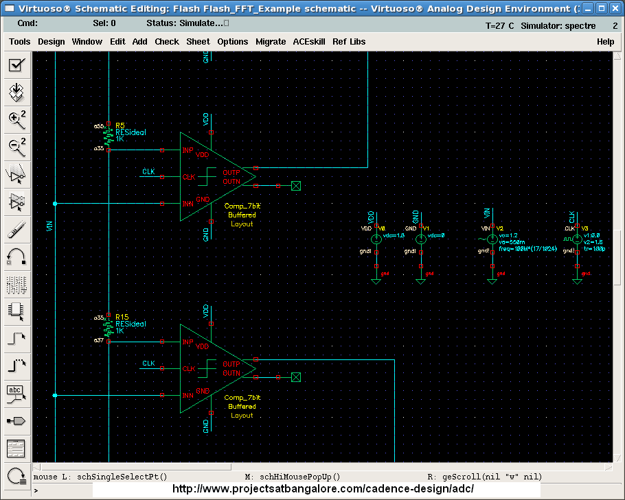
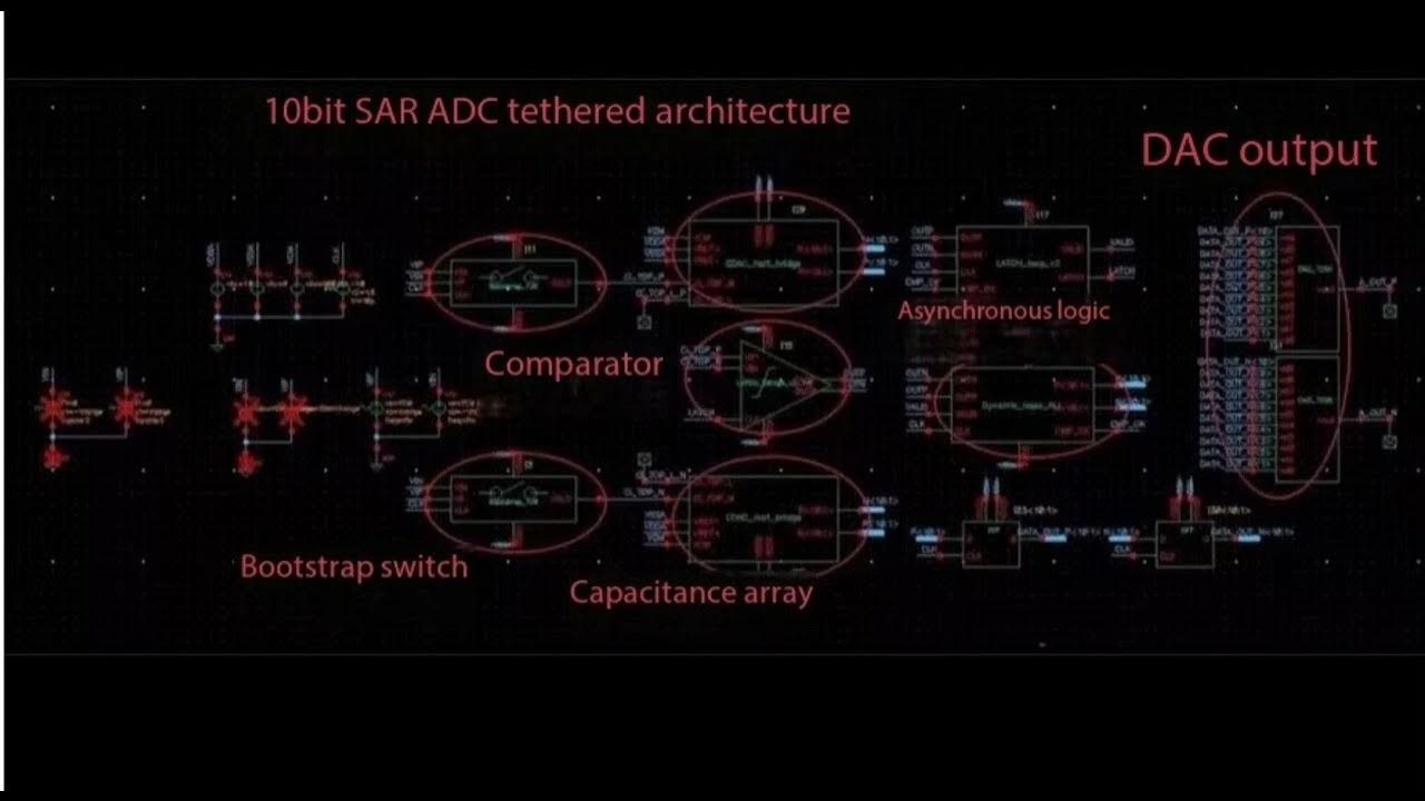
Cadence Virtuoso Schematics & Spectre Waveforms
Verified circuit schematics, physical layout topologies, and transient simulation waveforms.
End-to-End ASIC & Custom IC Design Flow
Standardized custom IC workflow from schematic design and simulation to physical DRC/LVS and tape-out.
(Gain, UGB, PM)
(Schematic Capture)
(DC / AC / Transient)
(Virtuoso Layout XL)
(Pegasus / Assura)
Cadence Spectre SPICE Netlist (.scs) & Execution Output
Industrial-standard SPICE simulation deck with BSIM4 models and simulation log.
Spectre (R) Circuit Simulator -- Version 21.1.0.612.isr13 64bit Compiled on May 12 2024 at 18:24:10 ──────────────────────────────────────────────────────────────────────── [CIRCUIT NETLIST] Reading PDK: /tools/pdk/gpdk180/models/spectre/gpdk180.scs [DC OPERATION] Convergence achieved in 5 iterations: - M1/M2 Vds = 0.842 V | gm = 1.84 mS | Vgs - Vth = 142 mV (Sat) - Quiescent Current Idd = 420.5 uA | Total Power = 756.9 uW [AC ANALYSIS] Open-Loop Gain A0: 72.4 dB (Target > 65 dB) [PASSED] [AC ANALYSIS] Unity-Gain Bandwidth: 54.2 MHz (CL = 10 pF) [AC ANALYSIS] Phase Margin (PM): 65.4° (Target > 60°) [STABLE] [TRANSIENT] Slew Rate (SR+ / SR-): 48.2 V/us | Settling Time: 18.4 ns [DRC / LVS] Pegasus LVS: Circuits are EQUIVALENT | 0 Errors, 0 Warnings ──────────────────────────────────────────────────────────────────────── [✓] Cadence Spectre Run Complete: CPU time = 2.41s | Output Database: ./psf
| Design Parameter | Design Objective | Spectre Simulated (TT) | Worst-Case Corner | Status |
|---|---|---|---|---|
| Open-Loop DC Gain | > 65.0 dB | 72.4 dB | 68.1 dB (SS) | PASSED |
| Unity-Gain Bandwidth (UGB) | > 40.0 MHz | 54.2 MHz | 48.5 MHz (SF) | PASSED |
| Phase Margin (PM) | > 60.0° | 65.4° | 61.2° (FS) | STABLE |
| Total Power Dissipation | < 1.0 mW | 756.9 uW | 910.4 uW (FF) | OPTIMAL |
| Slew Rate (SR) | > 35 V/us | 48.2 V/us | 42.0 V/us (SS) | PASSED |