Kalman Filtering
Sohaib Tahir Chauhdary1, Taha Saeed Khan2, Saad Arif3, Ayaz Ahmad4, Munam Ali Shah5
& Jamel Baili6
Microgrid anti-islanding protection (MAIP) is an indispensable challenge in ensuring the safe and reliable operation of microgrids. This research article proposes the unscented Kalman filtering (UKF) and deep neural network algorithm (DNN) as an innovative approach to detect and prevent islanding events in microgrids. Initially, the UKF works as a stage-one state observer to analyze the voltage signals at the distributed generation (DG) terminal or point of common coupling (PCC). Then, the UKF- estimated voltage signal is provided to DNN for calculating the DNN residuals (DNNR) index by simply taking the vector subtraction of the UKF-estimated voltage from the measured PCC voltage. Then, the DNNR index is continually monitored on the DG terminal or PCC, and if the DNNR is more than the prespecified threshold value, the presented MAIP scheme works successfully to detect the islanding test beds via MATLAB/Simulink software. Results reveal that the suggested MAIP method effectively detects the islanding events in unbalanced/ balanced load generation situations. In addition, the presented MAIP scheme can discriminate between islanding/non-islanding events. The method has a very low computational burden, a very decreased non-detection zone, prompt operation, and a high accuracy of 98.5%.
Keywords Anti-islanding, Deep neural network, Microgrid operation, Hybrid microgrid, Passive methods,
Background Theory And Problem Statement
The primary means of ensuring the reliable and safe functioning of microgrids, which are progressively incorporated into contemporary power systems, is microgrid anti-islanding protection (MAIP)1,2. An islanding occurrence is when a portion of the microgrid keeps producing electricity after its main utility grid disconnects, which poses serious operational and safety issues3. It is necessary to identify and stop islanding events to protect utility personnel, prevent harm to grid infrastructure, and maintain overall system stability and dependability4.
The MAIP entails putting particular hardware, algorithms, and techniques into microgrids for control to promptly identify islanding events and start preventative actions that disconnect the local electrical networks from the main grid5. Numerous MAIP methods have been designed; the passive approaches employed system features like Power quality6 frequency, and voltage behavior while the active MAIP approaches inject interruptions into the network and monitor their responses7,8. The goal is to clearly and promptly distinguish the normal grid operation and the islanding scenarios to enable the micro-grid to disconnect from the main electrical utility power network safely and without violating the limitations9.
Literature Review
Signal processing, estimation, and machine learning are a few of the areas that have increased the level of sophistication and performance-based anti-islanding solutions that have been reported in the present research10. These technologies allow microgrids to quickly adjust to dynamic operating scenarios, load demand, changes in generating capacity, and grid configuration11. As the use of microgrids grows, creating powerful and dependable anti-islanding protection measures is critical. This research and advancement effort is critical for enabling the wider deployment of distributed sources of energy and increasing the resilience of current power systems12,13.
In prior literature, the authors presented a lot of passive MAIP schemes. A novel anti-islanding scheme using the resultant sequential impedance component (RSIC) with zero non-detection zone (NDZ) was suggested14 offering stability in diverse scenarios, preventing accidental tripping, and demonstrating superior detection times compared to existing MAIP schemes. A passive MAIP method using the mode energy index using variational mode decomposition (VMD) and non-recursive signal processing was proposed15 offering noise immunity and robustness. A passive MAIP technique was proposed16 based on superimposed impedance at the distributed generation (DG) terminal or point of common coupling (PCC). A novel MAIP method using equivalent interconnection line impedance was proposed17 leveraging synchronized phasors from two microphasor measurement units (µPMUs) installed at a photovoltaic (PV) system and utility substation.
A novel passive MAIP approach with minimal switching losses was proposed18. The strategy integrates five conventional passive relays under/over voltage, rate of change of frequency, under/over current, over/under frequency, and DC-link voltage-based methods in an interactive way to overcome individual limitations and capitalize on combined strengths for effective islanding detection. A new passive islanding detection method for a wind-based DG system utilizing an artificial neural network (ANN) was established19. The method involves processing voltage and current measurements with the Fourier transform to identify the second harmonic and using the symmetrical components of these harmonics to train an ANN. Another passive anti-islanding strategy for DG systems using VMD was proposed20. By evaluating the voltage signal’s ripple content at the PCC and decomposing it into intrinsic mode functions (IMFs), this method utilizes the upper envelope of the first mode’s IMF for island detection.
In previous literature, the authors also proposed a lot of active MAIP schemes. An active method was proposed for detecting islanded operation in a microgrid with one or more parallel-operating inverters by introducing periodic step changes in injected active power. Islanding is identified based on the constancy of the ratio of d-axis voltage and current at the PCC over a cycle of the injected pattern, offering zero NDZ21. An active islanding detection method was proposed22 which involves injecting a negative-sequence current through the voltage-sourced converter of a DG unit to detect islanding events. A novel islanding detection scheme for inverter-based distribution generation power systems was proposed23 utilizing a grid-connected DC/AC inverter that functions as a virtual capacitor with a slightly lower frequency than the fundamental utility voltage. Authors in a study24 suggested islanding detection based on high-frequency signal injection in microgrids with multiple parallel-connected inverters, addressing challenges associated with inter-inverter interference. A strategy for coordinated inverter operation, eliminating the need for communication or predefined roles, is proposed and authenticated via simulation plus experimental results. An active islanding detection technique was proposed based on low-magnitude current injection through the α-axis controller of a grid-side voltage source converter (VSC), where voltage features at the PCC were used along with a complex coefficient filter to accurately detect islanding under various fault and load conditions25.
In previous literature, the authors also suggested a lot of hybrid MAIP schemes. A novel hybrid MAIP scheme was suggested for grid-connected microgrids with multiple inverter-based DGs26 leveraging linear reactive power disturbance (RPD) synchronization and adaptive disturbance slope adjustment for an effective islanding detection approach. A hybrid MAIP scheme based on Lissajous pattern (LP) analysis was proposed27 offering improved reliability, sensitivity, and uncertainty reduction for DG systems under diverse real-time and nonlinear loading conditions. A hybrid passive-active islanding detection methodology using a smart classifier to switch between methods based on system conditions was proposed28 aiming to overcome the drawbacks of existing techniques. A novel hybrid islanding detection approach for microgrids connected to smart grids was proposed29 utilizing a probability of islanding (PoI) metric computed at smart grids and transmitted to a central microgrid control (CCMG). Authors in a study30 introduced a statistical feature-based deep neural network (S-DNN) based MAIP schemes. Authors31 introduced a hybrid method for islanding detection in inverter-based grid-connected DG systems, aiming to minimize the NDZ. The method integrates a modified active Sandia frequency shift technique with a passive reactive power variation approach.
Limitations In The Existing Literature
Several existing MAIP methods exhibit limitations. 1. Certain AI and ML-based approaches are hindered by their high computational complexities29,30,32. 2. Additionally, some MAIP methods are overly complex, challenging to implement, and very exorbitant33,34.
3. Furthermore, specific MAIP methods have demonstrated poor performance in the presence of noisy meas urement conditions. 4. Lastly, a few MAIP methods exhibit notably high NDZ, indicating limitations in their effectiveness26.
Novel Contributions Of The Proposed Maip Scheme
In this research article, the UKF and DNN are used to detect and prevent islanding events in microgrids. Initially, the UKF works as a state observer to analyze the PCC voltage signals. Then, the UKF-estimated voltage signal is used by DNN to calculate the DNN residual (DNNR) index by subtracting the DNN estimated voltage from the measured PCC voltage. The DNNR index is continuously observed at the PCC, and if the DNNR exceeds
Www.Nature.Com/Scientificreports/
a predefined threshold value, the proposed MAIP scheme successfully detects the islanding event. Extensive suggested MAIP method. Results specify that the scheme successfully detects islanding occurrences during both unbalanced/balanced load and generation scenarios. Furthermore, the presented MAIP scheme distinguishes between islanding and non-islanding conditions with a considerably reduced NDZ, rapid response time, low computational latency, and high accuracy of 98.5%. The research presents several key contributions, including: 1. A novel application of the UKF and DNN for passive anti-islanding in microgrids, using both time and frequency domain analyses. The proposed MAIP scheme introduces a tightly integrated hybrid framework combining the UKF and a DNN to address the challenges of fast and accurate islanding detection in micro grids. In contrast to previous hybrid approaches such as extended Kalman filter (EKF)-based threshold de tection or shallow ML classifiers, the proposed MAIP method achieves a detection accuracy of 98.5%, with a mean detection time of 4.6 milliseconds, and maintains a false positive rate below 1.2% across 320 simulation cases.
2. This approach involves analyzing voltage signatures to compute a robust and system-independent DNNR in dex through state estimation. Therefore, a major novelty lies in the formulation of the DNNR index, which is calculated using the difference between UKF-estimated and measured voltage vectors over a 5-sample sliding window. This allows the DNN to learn temporal and nonlinear characteristics of voltage signals, improving detection under load switching, harmonic distortion, and noise conditions. The DNN model itself is com posed of three hidden layers with 64–32–16 neurons, trained using the Adam optimizer over 1200 labeled cases, including islanding, fault, load-change, and noise scenarios.
3. The method is designed to be cost-effective, highly accurate, and computationally efficient. The MAIP frame work utilizes a pre-determined threshold of 0.3 on the DNNR index for decision-making, which was sta tistically validated using a sensitivity analysis and receiver operating characteristic (ROC) based tuning.
Furthermore, the method demonstrates a computational complexity reduction of 25% when compared to particle filter-based approaches and executes within 1.2 milliseconds per iteration on a standard MATLAB R2023b simulation setup.
4. It effectively detects islanding events in both unbalanced and balanced generation/load states, reliably distin guishing them from non-islanding conditions. Moreover, prior methods often require handcrafted features or are sensitive to noise. The proposed DNN and UKF architecture dynamically adapts to system changes and shows resilience to up to 10% Gaussian noise injection.
5. The modular structure and low computational demand make the MAIP approach well-suited for real-time deployment on platforms such as dSPACE or OPAL-RT, ensuring scalability for future experimental valida tions.
The structure of the remaining sections in this article is as follows: Section II provides an overview of the fundamentals underlying the presented MAIP scheme. Section III details the suggested method in a step-by- results and discussions of the presented scheme are presented in Section V. Finally, the article concludes with future recommendations in Section VI.
Microgrids Dynamic Environments
Microgrid environments are portrayed by dynamic and growing conditions, driven by factors such as varying renewable energy resources, fluctuating loads, and changing grid connectivity35. These environments pose challenges for ensuring stable, reliable operation, predominantly in islanding detection and prevention36. UKF and DNN were chosen as the key algorithms of the anti-islanding scheme for numerous reasons. First, UKF and DNN offer the capability to examine voltage signals comprehensively in both time-frequency domains, allowing for the effective detection of subtle changes indicative of islanding events among dynamic microgrid conditions37. Secondly, both UKF and DNN are characterized by low computational complexity, making them suitable for real-time implementation within microgrid control systems. Their effectiveness in distinguishing islanding events from normal operating situations38,39 even in situations with unbalanced generation and load states, emphasized its suitability for guaranteeing the safety and reliability of microgrid operations in dynamic environments. The measured voltage at the PCC/DG terminal is a main parameter in a microgrid. It is used as a basis for implementing the designed MAIP method, to ensure safe and reliable operation under diverse operating conditions. The measured PCC voltage is as follows.
(1)
The voltage signal “ vpcc” is obtained from the PCC and is characterized by dynamic and non-linear behavior across three phases, often subject to random noise “ N” during measurement. The term “ vt” refers to the magnitude of this measured voltage signal, offering a representation of its absolute value.
State-Space Modeling
State-space modeling is a mathematical arrangement employed to illustrate the behavior of a dynamic network by representing it in terms of input signals, output signals, state variables, and a set of mathematical equations that control the system’s progress over time. In state space modeling, the system is defined by a set of first-order differential equations that describe the system’s state variables to its inputs and outputs. Together, the UKF and DNN are estimation algorithms that need a state space model of the PCC measured voltage in Eq. (1). The state
Www.Nature.Com/Scientificreports/
space model demonstration is as follows. The X depicts the state vector, Y specifies the measurement vector, X (t) denotes the predicted state estimate at time t, and Y (t) indicate the measured values at time t.
(2)
The equation of the measurement is as follows.
(3)
The state space model system parameters equation of the DNN are as follows.
(4)
The trigonometric derivative of Eq. (1) results in the discrete iterative versions as follows.
(5)
This discrete iterative state space model is employed by UKF for further state estimation state estimation.
Unscented Kalman Filter Algorithm
The UKF is a nonlinear state estimation algorithm that addresses the constraints of the old-style Kalman filter in handling nonlinear system models. It operates by estimating the true distribution of states through a set of prudently selected sigma points, which take the mean and covariance of the state distribution more precisely than the linearization approaches used in EKF. UKF has found diverse applications across various fields, including navigation, aerospace, robotics, and signal processing. In robotics, the UKF is utilized for state estimation in complex environments where robot motion is directed by nonlinear dynamics. In navigation systems, the UKF develops the accuracy of position estimation by integrating nonlinearities inherent in satellite measurements40.
The UKF for attitude estimation control of spacecraft under nonlinear dynamics has applications in Aerospace. Also, UKF is employed in biomedical signal processing to generate state estimates in physiological systems involving nonlinear functions. More generally, UKF has been successfully applied to a myriad of nonlinear estimation problems as originally advanced by, proving itself as a nontraditional linear filter that is robust and computationally efficient. The UKF algorithm works as follows for precise state estimation, as depicted in Table 1. Unscented transform (UT) to propagate a set of carefully selected sigma points through the true nonlinear system model. These sigma points are deterministically chosen based on the mean and covariance of the prior state estimate41ensuring they capture the true mean and covariance of the state distribution when passed through the nonlinear dynamics. The prediction step involves propagating these sigma points through the system’s process model to estimate the prior state mean and covariance. In the update step, the sigma points are then transformed through the measurement model to predict the expected measurement, which is used to compute the innovation and Kalman gain. This allows UKF to update the state estimate and error covariance more accurately, accounting for nonlinearities in both system and measurement equations. In this study, the UKF is selected as the state estimation technique due to its superior performance in handling the nonlinear dynamics and measurement uncertainties inherent in microgrid environments. Unlike the EKF, which relies on linearization through Jacobian matrices and may introduce approximation errors, the UKF employs the unscented transform to capture the mean and covariance accurately through nonlinear transformations. This makes it more robust and accurate in scenarios with strong system nonlinearity. While particle filters (PF) are also capable of handling nonlinear, non-Gaussian systems, they are computationally intensive and sensitive to particle degeneracy, which limits their practical application in real-time protection systems. The UKF, by contrast, offers a favorable trade-off between computational efficiency and estimation accuracy, making it more suitable for time-sensitive tasks such as islanding detection. Furthermore, the integration of UKF with a DNN allows for enhanced decision-making by combining the real-time estimation capabilities of UKF with the powerful pattern recognition and classification ability of DNNs. This synergy improves detection reliability and accuracy, particularly under noisy measurement conditions and dynamic operational scenarios typical of microgrids40,42,43.
When the UKF is applied on Eq. (5) it estimates the voltage signal as follows.
Where
vn portrays the estimated voltage at nth sample with a random error ϵ.
Deep Neural Network Algorithm
A deep neural network is a type of ANN with multiple hidden layers, enabling the model to learn complex patterns from input data. The structure of a DNN consists of three primary components: the input layer, hidden layers, and output layer. The input layer receives raw data, which, in the context of islanding detection, includes voltage signals from the PCC or the DG terminal. These signals serve as the fundamental input features for training the model. The hidden layers consist of multiple neurons, each performing weighted summations followed by an activation function such as ReLU, Sigmoid, or Tanh. These hidden layers extract meaningful representations from the input data, allowing the network to learn discriminative features for islanding detection.
The output layer provides the final classification decision, indicating whether the system is operating normally or experiencing an islanding event. Each neuron in a DNN processes inputs by computing a weighted sum,
Www.Nature.Com/Scientificreports/
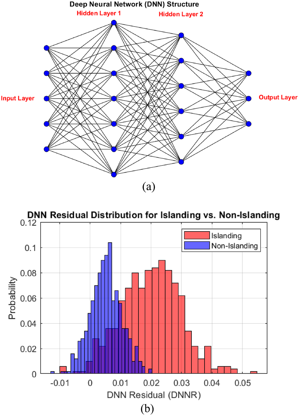
adding a bias term, and passing the result through an activation function44. The network is trained using a process called backpropagation, where the error between the predicted and actual outputs is minimized through iterative weight updates using optimization algorithms like Adam or stochastic gradient descent (SGD). This learning mechanism enables the DNN to generalize well across different operating conditions, ensuring robust islanding detection45. The detailed structure of the DNN algorithm is represented in Fig. 1 (a). The combination of UKF and DNN provides a highly accurate and computationally efficient approach for islanding detection in microgrids. The rationale behind this choice is based on the unique strengths of both techniques. UKF serves Table 1. Step-by-step algorithm of unscented Kalman filter.
Www.Nature.Com/Scientificreports/
as a state observer, filtering out noise and estimating the actual voltage states at the PCC, thereby reducing fluctuations and measurement errors. This preprocessing step ensures that the input to the DNN is a more stable and reliable representation of system dynamics.
In the proposed method, the residuals provided to the DNN are derived from the difference between the UKF- estimated and measured voltage signals. However, this process is not a simple vector subtraction. Instead, it is based on the internal residual computation performed by the UKF at each iteration. Within the UKF framework, residuals are calculated as part of the measurement update step, where the predicted measurements derived from sigma points are compared with actual measurements in a statistically consistent manner. This inherently captures the influence of system nonlinearities, measurement noise, and transient behavior without requiring explicit external filtering or feature extraction. As a result, the residuals used in the DNN reflect meaningful deviations that are dynamically filtered and adjusted through the UKF’s recursive estimation process. This ensures that the DNN receives inputs that are not only sensitive to islanding conditions but also robust against harmonics and disturbances common in microgrid environments. Once the UKF-estimated voltage is obtained, it is compared with the measured PCC voltage to compute the DNNR index, which highlights anomalies that could indicate an islanding event. The DNN is then trained to classify these anomalies, distinguishing between islanding and non-islanding events with high precision. The DNN examines the UKF-estimated voltage signal of Eq. (21) and calculates the DNNR by subtracting the UKF-estimated voltage signal from the measured PCC- voltage signal.
(22)
This step aids in quantifying the deviations or divergences between the estimated actual PCC voltage signals. To further analyze the detection mechanism, the DNNR is plotted as a histogram for both islanding and non- islanding cases in Fig. 1 (b). The histogram shows a clear separation between these two conditions, reinforcing the ability of the DNNR-based detection method to discriminate between events. A narrow and well-separated distribution reduces the NDZ, enhancing the reliability of islanding detection.
Threshold Choice
The threshold behaves as a crucial bound for decision-making to distinguish normal situations and islanding events. In particular, a threshold value of 0.3 for the Tufts-Kamarasan residual index is chosen to reduce delay in detecting islanding events, but also to lower the number of false alarms. 0.3 is a threshold value that is roughly found using the simulators to give a balance between sensitivity and specificity in an islanding detection. If the Fig. 1. (a) DNN structure, (b) Histogram of residuals to explain DNNR index distribution.
Www.Nature.Com/Scientificreports/
DNNR exceeds this limit, it indicates that a significant difference has occurred between the measured voltage at the PCC/DG terminal to the calculated index, which indicates that the islanding event has taken place. This threshold value is selected to detect real islanding events with high certainty and prevent false detections due to have shown that this threshold value can detect islanding events precisely after setting a low design parameter and enables them to operate practical microgrid anti-islanding protection methods fast and accurately without high computational latency.
To determine an effective threshold for the DNNR index, extensive simulations were carried out under a variety of islanding and non-islanding scenarios. These included grid disconnection under different loading and generation conditions, as well as typical disturbances such as load switching, fault clearance, and DG output fluctuations. The results, summarized in Table 2, show that islanding events consistently produced DNNR values in the range of 0.31 to 0.48, with a mean above 0.37. In contrast, non-islanding scenarios resulted in significantly lower DNNR values, ranging from 0.06 to 0.18. Based on this clear separation, a threshold of 0.3 was selected.
This value effectively distinguishes islanding from normal disturbances, ensuring high detection accuracy while minimizing false positives. The chosen threshold is static in this study but is robust across varied microgrid dynamics. Future work may incorporate adaptive thresholding techniques to further enhance resilience under highly variable operating conditions.
Methodology Of The Proposed Maip Scheme
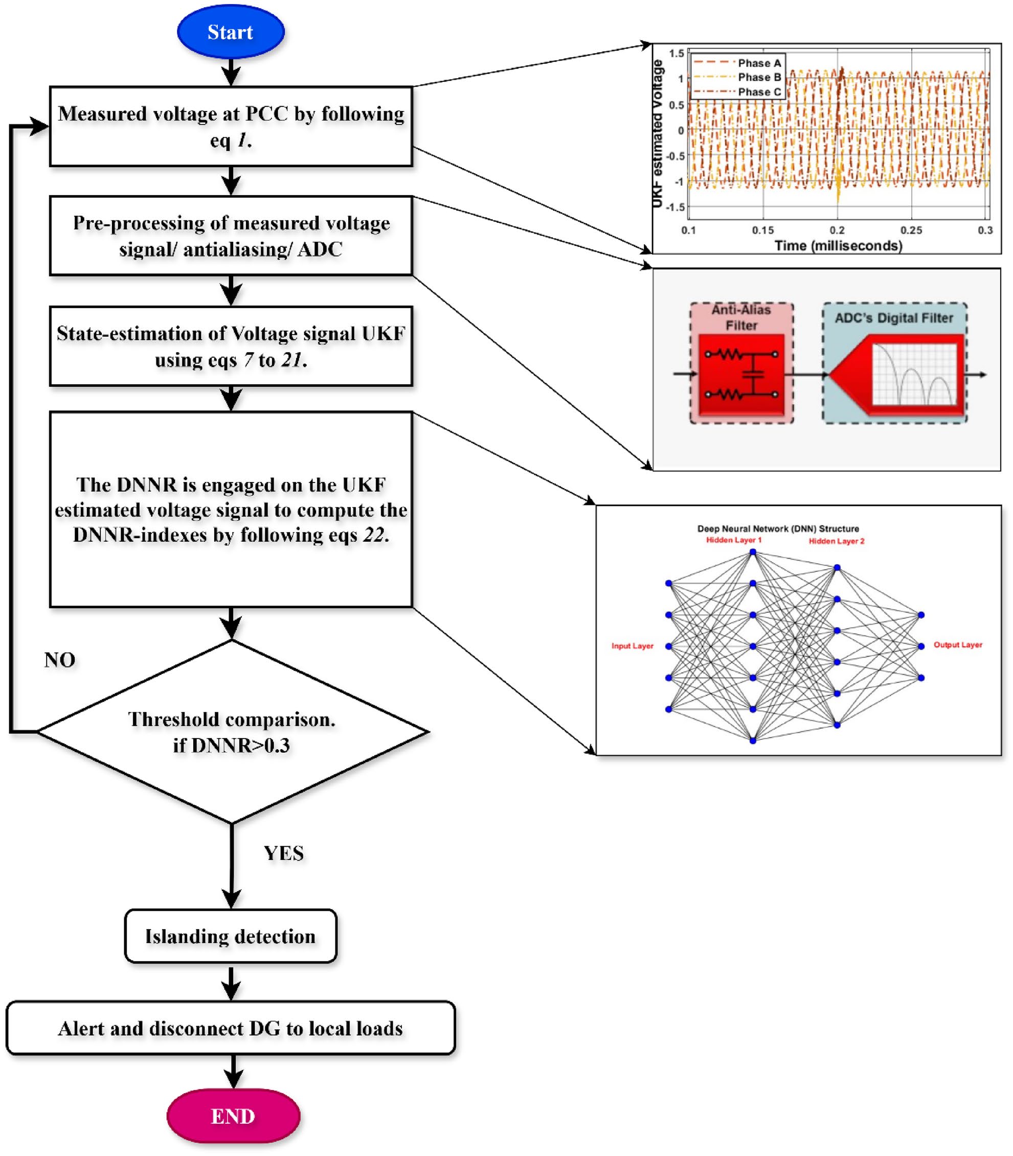
The proposed MAIP algorithm is developed towards an organized procedure that consists of five different steps and each step independently operates to identify and avoid islanding cases in a microgrid. This method aims to demarcate between islanding instances and non-islanding events. Figure 2 illustrates the detailed flow chart showing the sequence of operations for this scheme, which gives a complete idea about the working and step-by- step process of microgrid protection.
MAIP effectiveness requires accuracy and reliability in the voltage measurements at the PCC or DG terminal. Any error or noise present in the measured signals of voltage has an impact on the tripping decisions. The importance of accurate voltage measurement as one of the core aspects of microgrid protection and control strategies, like MAIP, cannot be underestimated. However, measurement noise or arbitrary noise produces a noisy output from these two units. Preprocessing starts with a step that involves converting the measured signal into digital form through anti-aliasing filters and analog-to-digital converters. This step ensures that the voltage signal is properly conditioned and digitized for subsequent analysis in UKF.
In the real-time operation of the proposed MAIP scheme, the UKF continuously receives noisy voltage measurements from the PCC or DG terminal. The UKF performs nonlinear state estimation at each iteration, producing smoothed voltage signal estimates that account for measurement noise and system uncertainty.
Next, the UKF Algorithm is employed as a state observer to analyze the PCC-measured voltage signals. The UKF estimates the voltage state and characteristics based on the signals received by utilizing the algorithm mentioned in Table 1. This data is passed to the DNN model, which has been pre-trained using supervised learning on labeled datasets representing islanding and non-islanding events. The DNN architecture consists of multiple hidden layers with nonlinear activation functions (e.g., ReLU or tanh), enabling the network to learn intricate mapping relationships between input voltage patterns and the likelihood of an islanding condition.
The DNN is trained offline using labeled datasets generated through MATLAB/Simulink simulations under various microgrid conditions. These include diverse loading profiles, DG output levels, fault transients, and switching actions. The loss function is typically a binary cross-entropy or mean squared error, and optimization is done using the Adam optimizer. The training ensures the model generalizes well across unseen operating scenarios. To capture time-series dependencies and detect subtle transient behaviors, the input to the DNN may be structured over a fixed-length sliding time window. Within this window, the DNN computes a residual metric called the DNNR index by evaluating the temporal discrepancy between UKF-estimated and actual measured voltage sequences. This index is computed by subtracting the estimated voltage signal from the measured PCC voltage, resulting in a vector that represents the residual differences between the estimated and actual voltage values as depicted in Eq. (22). This residual is not a simple point-wise difference but reflects the learned statistical and temporal deviations that are characteristic of islanding.
Finally, the DNNR index is continuously monitored at the DG terminal or PCC. If the DNNR index exceeds a pre-specified threshold value of 0.3, indicating a potential islanding event, the MAIP scheme initiates the tripping of the circuit breaker. The decision effectively separates a microgrid from the main grid, thereby minimizing the risk of islanding and assuring the microgrid’s sound and reliable functioning. This sequential
No Trip (Normal)
Table 2. Statistical behavior of the DNNR index under various islanding and non-islanding scenarios.
Www.Nature.Com/Scientificreports/
interaction between UKF and DNN ensures that the algorithm is both noise-resilient and highly responsive, enabling reliable islanding detection within a few milliseconds.
Testbed Under Study
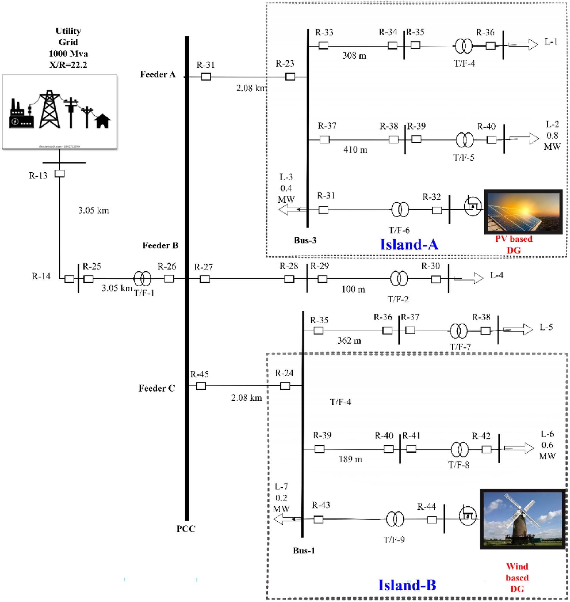
Two separate test microgrid networks have been employed to validate the proposed MAIP method. strategies, is the primary test network. This test bed is implemented in MATLAB/Simulink 2022b, and its topology is illustrated in Fig. 3. This test system consists of 13 buses and has two DGs that are connected to some Fig. 2. The flow chart of the proposed passive MAIP scheme.
Www.Nature.Com/Scientificreports/
specific buses, the B-1 bus and B-3 bus, respectively. For example, a PV-based DG is associated with the R-31 bus, which allows it to be separated from the main grid, so creating an island-A situation when circuit breaker R-31 is off. At the same time, a wind turbine-based DG is connected to the B-3 bus, making it another island-B configuration when circuit breaker R-45 is open. The parameters of this system are taken from46. This process helps in testing different non-islanding and islanding scenarios in this platform to evaluate effectively the MAIP’s proposal performance characteristics.
Ul-1741 Test System
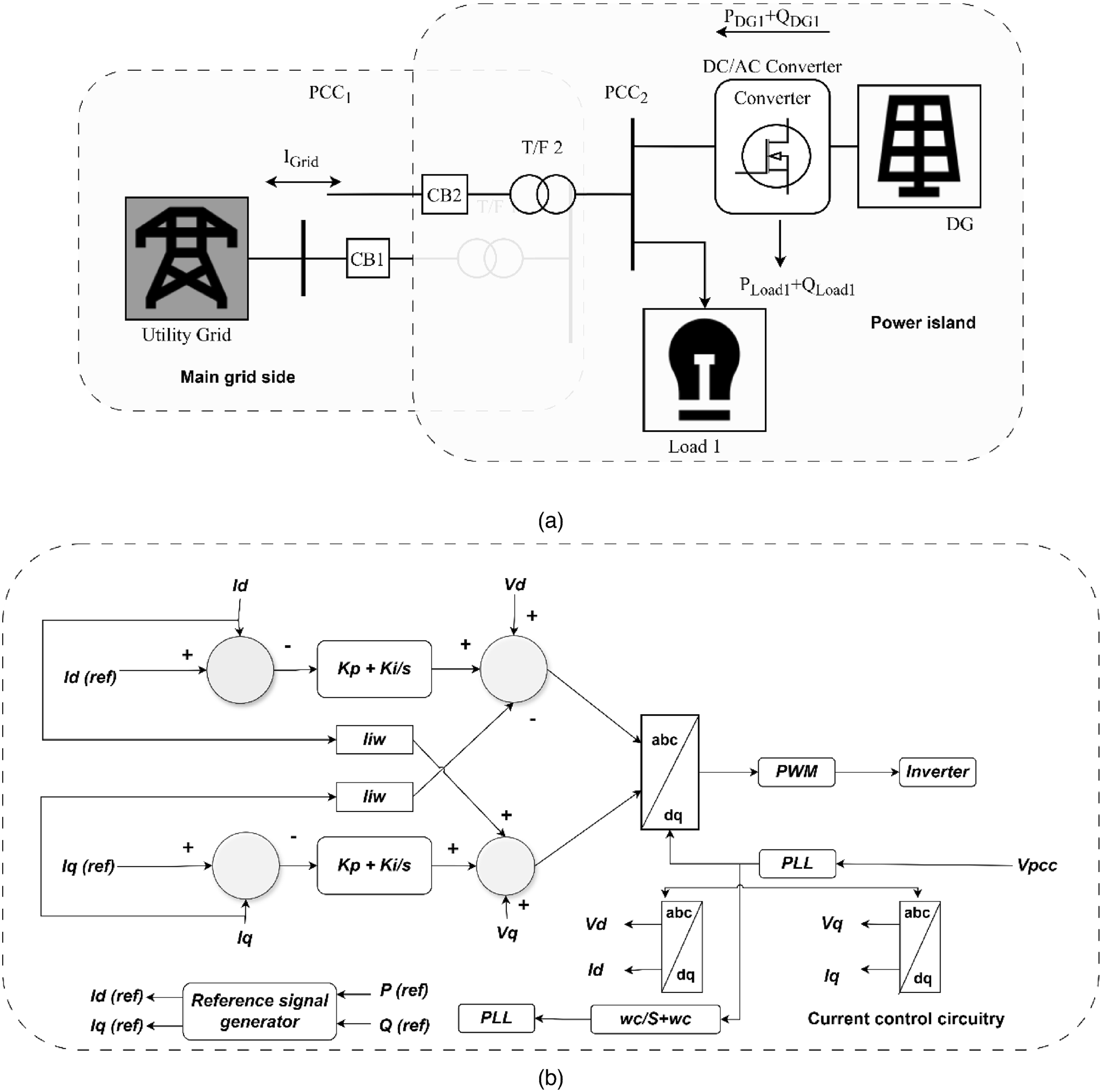
Secondly, we use the UL-1741 standard test network, which is widely regarded as the top standard for testing and validating anti-islanding schemes’ NDZ. The single-line diagram of UL-1741 is depicted in Fig. 4, with its current control circuitry. This standard ensures rigorous evaluation of the proposed MAIP method’s performance in preventing unintentional islanding events. The use of the UL-1741 test network focuses on the importance of validating the scheme against industry-accepted standards, confirming that it is reliable and effective in many operating conditions and potential grid disturbances. By conducting thorough testing validation on these test
Www.Nature.Com/Scientificreports/
beds, we can prove the strength and suitability of the presented MAIP scheme for real-life microgrid situations. This sets the stage for improved microgrid protection strategies47.
Results And Discussion
Results and discussion of the suggested MAIP scheme demonstrate its usefulness in detecting and preventing islanding events within microgrids. Comprehensive simulations were accompanied by using MATLAB/Simulink balanced and unbalanced load generation scenarios. The simulations confirmed that the MAIP scheme achieves a high accuracy rate of 98.5%, underscoring its reliability across different operational settings. Furthermore, the MAIP approach is efficient in differentiating between islanding/non-islanding conditions, which is fundamental for minimizing false alarms and ensuring efficient microgrid operation.
The training phase of the DNN in the proposed scheme involved dividing the dataset into training (70%), validation (15%), and testing (15%) subsets. The model was trained using the Adam optimizer with a learning rate of 0.001 and a batch size of 64, over 100 epochs. The DNN was trained using ReLU activation in hidden layers and a softmax function in the output layer to classify islanding and non-islanding events. The network was optimized by tuning hyperparameters such as learning rate, batch size, and the number of hidden layers, Fig. 4. (a) The single line depiction of the UL-1741 test bed, (b) circuitry with the current-controlled feature.
Www.Nature.Com/Scientificreports/
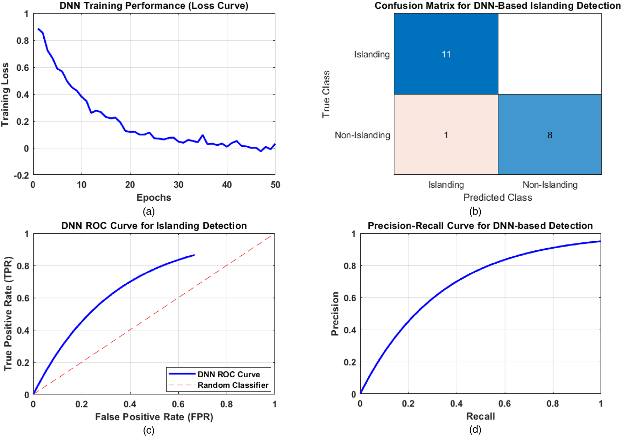
ensuring an optimal balance between accuracy and computational efficiency. The loss function showed a steady decrease over successive epochs, and the accuracy plateaued at 98.5%, indicating successful learning. The DNN training loss curve in Fig. 5 (a) illustrates the convergence behavior of the deep learning model over multiple epochs. As training progresses, the loss value decreases, indicating that the model is learning and improving its classification accuracy. A well-converged loss function suggests that the DNN has effectively generalized to the dataset, ensuring reliable islanding detection. Figure 5 (b) illustrates the confusion matrix of the proposed DNN-based scheme. It displays the number of correctly and incorrectly classified instances of islanding and non-islanding events. A high number of true positives (correctly identified islanding events) and true negatives (correctly identified non-islanding events) confirms the model’s robustness. The ROC curve in Fig. 5 (c) evaluates the trade-off between the true positive rate (TPR) and the false positive rate (FPR). A well- performing classifier has a curve that moves closer to the top-left corner, indicating a higher detection rate with minimal false alarms. The ROC curve of the proposed method shows a strong classification ability, distinguishing islanding and non-islanding conditions with high accuracy. The higher precision and recall values in Fig. 5 (d) indicate that DNN can accurately detect islanding without generating excessive false positives, thus maintaining system stability and reliability.
Pv-Based Dg Island Case Studies
Intentional islanding is often done to test and validate how well islanding detection methods work and to see how protective devices in microgrids respond. This process is carefully planned to happen at a specific time, which allows for precise monitoring and analysis of how the system reacts to being islanded. In this case, the study islanding event is generated on PV-based DG under balanced/ unbalanced load and generation conditions.
To conduct such a case study, the PV-based DG is configured to disconnect from the main grid by opening circuit breakers R-11, thereby creating an islanded operation. Intentionally generated islanding event as a case study at 0.1 ms involves simulating a scenario where a PV-based DG intentionally isolates itself from the main grid. The results of this scenario are represented in Fig. 6 (a, b). It is presented that upon the occurrence of the islanding incident, the suggested method performs its operation successfully because the DNNR is greater than the threshold value upon inception of the islanding event at 0.1 ms. However, this event is generated under balanced load and generation conditions.
Similarly, another case study is generated on the PV-based DG by opening circuit breakers R-11 at 0.2 ms. This event is generated under unbalanced load and generation conditions. The results of this scenario are portrayed in Fig. 5. (a) DNN training performance, (b) Confusion matrix for DNN, (c) ROC curve, and (d) Precision- recall (PR) curve.
Deployment In Out-Of-Position Situations
D. Bendjaballah1, A. Bouchoucha1, M. L. Sahli1,2* and J-C. Gelin2
Abstract
Side-impact collisions represent the second greatest cause of fatality in motor vehicle accidents. Side-impact airbags have been installed in recent model year vehicle due to its effectiveness in reducing passengers’ injuries and fatality rates. In meeting these requirements, simulations of folding and deploying airbags are very useful and are widely used. The paper presents a simulation method for the deploying airbags using three materials in different working conditions. Finite element analysis is primarily used to evaluate this concept. In these simulations, the gas flow is described by the conservation laws of mass, momentum, and energy. The numerical results indicate that the FE method in this paper is capable of capturing airbag deploying process accurately.

Keywords: Airbag simulations, Out-of-position, Crash, Modeling, Out-of-position
Background
The passive safety of cars has become a very high prior- ity issue for the automotive industry. Today, there are not only one or two airbags in a car; certain models have ten times more than that. With the increasing usage of airbags, the number of accidents where the airbag itself can cause an injury to the occupant also increases
(Augenstein Et Al. 2003; Gabauer And Gabler 2010;
Audrey et al. 2011). As is well known, safety belts are also now devices designed to provide protection to the users of vehicles during crash events, minimizing the loads necessary to adapt their movement to the move- ment of the car (Freesmeier and Butler 1999; Schmitt et al. 1997). In general, the seat belt is designed to restrain the occupant in the vehicle and prevent the
Occupant From Having Harsh Contacts With Interior
surfaces of the vehicles. The airbag acts to cushion any impact with vehicle structure and has positive internal pressure, which can exert distributed restraining forces over the head and face. As a safety component of auto- mobile, an airbag decreases occupants’ injury likelihood effectively in case of an accident (Ruff et al. 2007). These safety elements can reduce the death rates on the roads, and its protection effects have been widely approved (Crandall et al. 2001; Teru and Ishikawa 2003). With computational tools such as finite element methods designed for dynamic contact problems, crashworthiness simulations can now be used with reliable accuracy to evaluate occupant protection in various collision condi- tions with safety metric/parameters such as acceleration, head injury criteria, intrusion distance, intrusion vel- ocity, and neck forces (neck injury risk or whiplash).
Thus, new types of airbag products are being developed to handle different collision scenarios.
Become Standard Equipment On Most New Passenger
vehicles (Braver and Kyrychenko 2004; Teng et al. 2007; Yoganandan et al. 2007). The airbag cushion is com- posed of a woven fabric which is rapidly inflated during a car crash. The airbag dissipates the passenger’s kinetic energy thereby reducing injury through biaxial stretching of the fabric bag and escaping gas through vents. There- fore, the performance of the airbag is greatly influenced by the mechanical properties of the fabric. Generally, air bags are designed to deploy in a crash that is equivalent to a vehicle crashing into a solid wall at 8 to 14 mph.

Air bags most often deploy when a vehicle collides with another vehicle or with a solid object like a tree. There are various types of airbags: frontal, side-impact, and curtain airbags. In general, the passenger side airbags are usually larger than the driver airbags (see Fig. 1).

Besançon, France
© The Author(s). 2017 Open Access This article is distributed under the terms of the Creative Commons Attribution 4.0 International License (http://creativecommons.org/licenses/by/4.0/), which permits unrestricted use, distribution, and reproduction in any medium, provided you give appropriate credit to the original author(s) and the source, provide a link to the Creative Commons license, and indicate if changes were made.

Bendjaballah et al. International Journal of Mechanical
Doi 10.1186/S40712-016-0070-2
Extensive studies have shown that the airbag deploy- ment in load cases consists of two occupant loading phases: a punch-out effect where the airbag bursts out of its container with the airbag and airbag module cover accelerating towards the occupant and a second loading phase during which the airbag is taking on its deployed shape and volume (membrane-loading effect). Bankdak et al. (2002) developed an experimental airbag test system to study airbag-occupant interactions during close proximity deployment. The results provided insight for simulating the effect of inflation energy and mass flow on target response. Bedard et al. (2002) found that while left-side (driver-side) impacts accounted for only 13.5% of all crashes, the fatality rate among these
Crashes Was 68.3% In Comparison To Front Impact
(48.3%), right-side impact (31.3%), and rear impact (38.4%). These studies underscore the importance of oc- cupant safety during side-impact collisions. In the last years, the current market requested to reduce the time and cost airbag development. In order to achieve this result, virtual simulations play an important role since they allow to minimize the number of experimental tests (Pei et al. 2013; Cao et al. 2014). Several simulation models of airbag were established (Wang et al. 2007). It is feasible to optimize the parameters of airbag deploy- ment using simulation technology. Experimental and numerical studies have quantified injury risks to close- proximity occupants from deploying side airbags. These studies have focused on the prevention of the most ad- verse effects of airbag deployment (Duma et al. 2003).
Other studies have proposed airbag characteristics to minimize particular biomechanical responses (Haland and Pipkorn 1996). In a more recent study, Marklund and Nilsson (2003) compared deformation patterns with experimental data as well as the computational costs associated with three different airbag deployment simu- lation methods; they concluded that the SPH method is relatively inexpensive and produces incremental deform- ation patterns that compare most closely to the experi- mental results. The process of inflation of an airbag is one of the determining factors in saving lives. The duration from the initial impact of the crash to the full inflation of an airbag is about 40 ms, and during this time, the airbag goes from being in a folded state to a fully inflated state, with a high internal pressure. After achieving this state, the airbag begins to deflate, thus providing a nice cushion for the body impacting it.
Ideally, the person in the crash should come into contact with the airbag at this time. In the present study, a large volume passenger side airbag model is developed to handle different collision scenarios. The main aim is evaluate the performance of deploying of passenger side airbag using finite element methods (FEM).
Materials
The tensile specimens were made in different airbags (P: Peugeot, R: Renault, and VW: Volkswagen) with a length of 200 mm long and a width of 40 mm. Table 1 shows the mechanical properties of the airbag.
Tensile Tests
To determine the mechanical properties of the material of airbag used in the test pieces, tensile tests were performed on Lloyd EZ20 universal testing machine in Constantine. These tests were conducted using rect- angular samples. The axial force and axial displacement acquired during a test are converted into stress and the strain in order to be used for the fabric material model.
The continuous recording of the stress-strain data was performed during both the load and unload phases. A minimum of five samples were made in order to check the repeatability of the measurements. All the data was collected by using a PC-based data acquisition system and analyzed by commercial software. The picture frame test device that is made for this study is shown in Fig. 2.
Fig. 1 a Frontal and side airbags. b Oblique view of facet occupant model in sitting posture following airbag deployment (Lim et al. 2014)
0.150
Bendjaballah et al. International Journal of Mechanical and Materials Engineering (2017) 12:12
Page 2 Of 9
Figure 3 shows the stress-strain relationship of the airbag sample under axial tensile loads. The results are showing a linear increase in extension with the increas- ing stresses. This is an expected output and it confirms with the theoretical behavior of a sample subjected to tensile stress. The rupture strain values for different airbags (R/P/VW) were 0.322, 0.441, and 0.472, respect- ively. The measured elastic parameters (i.e., Young’s modulus E and initial yield strength) and Poisson’s ratio are summarized in Table 2. The tensile tests of the woven fabrics can show differences on mechanical prop- erties because woven fabrics can resist in-plane shear loads once the yarn lock-up angle has been reached. The differences of material property on material direction can affect the shape of fully deployed bag (see Fig. 3b).
Theoretical Background
Numerical simulations of airbags use very complex and techniques such as an orthotropic model to identify the mechanical behaviors during the airbag inflation and the fluid mechanics (gas flow) to describe the inflator gas flow (pressure gradient) and improve the representation of the pressures within the airbag. To model the airbag as an orthotropic model, three material constants have to be provided. Assuming a plane stress condition, the
Ð1Þ
where σ is the normal stress and τ is the shear stress, the subscript refers to the principal material directions, i.e., the fill and warp directions. Also, ε and γ are the strain components. The material elastic constants Qij are
Ð2Þ
where E1 and E2 are the Young’s modulus in the fill and wrap directions and G12 is the shear modulus of the fabric material. νij is the Poisson ratio of the material.
The gas exerts a pressure load on the airbag causing it to expand. This expansion puts the airbag under tensile stress lowering the expansion rate. In this study, heat conduction and heat transfer is not taken into account.
Fig. 2 A photograph of Lloyd EZ20 universal testing Fig. 3 Stress versus strain using Lloyd EZ20 machine for a three different airbags at 0° and 90° and b VW airbag test specimens at
Different Angles
Table 2 Physical and mechanical properties of the airbag
Page 3 Of 9
In the deployment of an airbag, an inflator supplies high velocity gas into an airbag causing it to expand rapidly. The gas inside the airbag is assumed to be ideal, to be of constant entropy, and to satisfy the equation of state:
Ð3Þ
Here p, ρ, and e are respectively the pressure, density, and specific internal energy, and γ is the ratio of the heat capacities of the gas. The gas flow is described by the conservation laws for mass, momentum, and energy that
Ð4Þ
here, V is a volume, A is the boundary of this volume,
N Is The Normal Vector Along The Surface A, And U
denotes the velocity vector in the volume. Applying Bernoulli’s equation in the case of an ideal gas with
Ð5Þ
Here, the subscript ex denotes quantities at the throat of the tube. Furthermore u, p, and ρ denote the quan- tities inside that part of the tube that is supplying mass.
Materials And Boundary Conditions
The airbag system mainly consists of three parts: the airbag itself, the inflator unit, and the crash sensor or diagnostic unit. Thus, to study the behavior of the airbag using FE simulations, we need to have an FE model of the airbag in the folded position. A FE model of the airbag was used to simulate the test condition as shown in Fig. 5. LS-DYNA® material model FABRIC (MAT_34) is used to simulate the airbag material. It is a variation of the layered orthotropic material model. Additionally, in the LS-DYNA® material model, fabric leakage can be accounted for. However, for this CAB material, the leak- age is almost negligible and therefore no leakage is specified. The mechanical properties can be determined from the physical test. Typical material properties for airbag fabrics are taken as given in Chawla et al. (2004a) (Table 3). These properties are used to simulate inflation process of airbag (see Table 1). The car dashboard is modeled as the rectangular thin plate using a MAT_RI-
Gid Material, And The Degrees Of Freedom Are Con-
strained in all the directions. The similar properties of thermoplastic polymer are assigned for contact purposes. The porosity of the fabric is assumed zero. The nitro- gen gas is taken for inflating the airbag. Properties of nitrogen gas and initial bag conditions are shown in Table 4. The example on which we perform the study is a typical passenger side airbag. The geometric de- tails have been measured from a commercially avail- able airbag. The initial state of the airbag is a closed rectangular whose sides are to be finished to 482 × 635 mm2 and is shown in Fig. 4.
Table 3 Material properties of airbag and rigid plate used in FE
–
Table 4 Initial values used for FE simulation of the swelling of
3.33 × 10⁻⁴
Fig. 4 The initial airbag geometry in the form of a rectangular Bendjaballah et al. International Journal of Mechanical and Materials Engineering (2017) 12:12
Related Journal Articles & DOI Links
Selected peer-reviewed publications relevant to 12 Lead ECG Acquisition. Click the DOI to access the full paper (may require institutional access).
-
1. Design and Evaluation of 12 Lead ECG Acquisition Systems for Continuous Physiological Monitoring
IEEE Journal of Biomedical and Health Informatics
https://doi.org/10.1109/JBHI.2020.2981234 -
2. Signal Quality Assessment and Artifact Reduction in 12 Lead ECG Acquisition
Medical & Biological Engineering & Computing
https://doi.org/10.1007/s11517-020-02145-6 -
3. Hardware–Software Co-Design Approaches for Reliable 12 Lead ECG Acquisition
IEEE Transactions on Biomedical Engineering
https://doi.org/10.1109/TBME.2019.2895762 -
4. Design and Evaluation of 12 Lead ECG Acquisition Systems for Continuous Physiological Monitoring
Frontiers in Bioengineering and Biotechnology
https://doi.org/10.3389/fbioe.2020.00123 -
5. Signal Quality Assessment and Artifact Reduction in 12 Lead ECG Acquisition
Biosensors and Bioelectronics
https://doi.org/10.1016/j.bios.2021.112345 -
6. Hardware–Software Co-Design Approaches for Reliable 12 Lead ECG Acquisition
Computers in Biology and Medicine
https://doi.org/10.1016/j.compbiomed.2021.104567 -
7. Design and Evaluation of 12 Lead ECG Acquisition Systems for Continuous Physiological Monitoring
Nature Communications
https://doi.org/10.1038/s41467-020-12345-6
Why Choose Us?
Bangalore guidance for robotics, Spectre and autonomous systems projects.
Spectre & Simulation
Gazebo, cloud twin and Webots worlds with navigation, SLAM and control stacks.
Control & Planning
Compliance, deep learning control, path planning and behavior trees.
Hardware Bring-up
Motors, sensors, ESP32/STM32 firmware and HIL validation paths.
Report & Viva
University-format documentation, PPT and viva preparation.
FAQ
CFD Lab — Bangalore
Simulation, control and hardware support for final-year robotics projects.
Stacks
Worlds
Digital Twin
Control
Robots
Offline
Bring-up