.10450 Shah Alarn, S€Langu, Malaysia
Ahstract- Ttir prpcr prt!.rl! thc .ppli.rtlon of ringle pbrrc mrlrir conv.rld ( SPMC ) rr rn AC-DC corlroll.d rrctllLr with th. cff!.t of pr!.rivc liltlr. For brsic opcnaiolr, multiplc PWM tcthniqo.s rtr ur.d l! r rrrltchiig bailhu. to !yolb6L.
th. o.tprt voltaF rld c.rEat 8..5G.. c{or.t li.rr rfra.S/ rrr &vclopcd ao .vold ov.rLppht durlq tur! ON ..d turtr OFF ltll of ti. IGBTr rlcr hdrctivc loede .rr I' d. FiL.ri!! rcqdrtoala! for currall-roorcr .talifial! att lrlllly t.firfiod through lhc ulc of Pl.6lvc Filt r Bhhh i! low-p.!! LC iDpua llh.rr Dcdgn of LC fllt n itrvoly.! tL pclriotrbt of tL raolrrtrt fatquctrcy to m.Gt th. harDorlc rttcnc.tlo! r.!quittmaDt!.
hantlonics hav€ lcgc current magdtud€s Efcr to th?ir h8monic specEur. The hannonics gcrErst€d will be divided into tlrEc tlpcs ollt is pcitive scqr.Enc€s hsrElotric components such as 70l , l3tb, l9th rrd n€gative rcquarc. hslmoric compoornts such as 5th, I llh, l7th tha is cxccssivc in plEs. lh€ which iDc{ras. thc THD ofhe slstqrt. Wtilc zero seqt.EDc.s hErnooics c'ullrnt that is tiplctr hrmrqrics sudl 6 3, 9, 15 will floqrs drcugh dE ncqlral wir! &d nuy crulr€ ov.drcdinS m thal wirr [81. Siryle nrcthod for minimizing tIE harmooics supply cuflut diitortidl associared wi$ SPMC !3 r rcctififi fd LC (inpd filtrr b prEsented by using Plcaive filter.
Introduction
Thc rutrix cmverter (Mc) offc's pciblc 'all silicon" soluticn for AC-AC convqsioo, rEmoving tho nocd for rca{tiw c'notE/ stonge compooqia rscd io cutwrtiooal cqwlttq syltctrL MC is ao ldv{rccd circuit topolos/ thEt ofrrf,s m{ty ldvdrtrg.s sudr as thc rbility to .!g€l!€rst! eolr$/ bd to l[c rxility, ciousoidsl itrput md ou&ur olrrEnt ed cootollEblc iryrd (rlnutt displaccarcnt frcra [ll.
Its topoloe/ wEs fll3t dBcribed by Gyugyi in 1976 [21. MC in tlE rturc,phrse vailnt is widely rcs€arphod whikt the Sirlgle Phsse MEtrix Coov€rtar (SPMC) has vcry litrlc d.dioo wlril* offeting very wide applic.arion SPMC w!6 first te lbed by zuckoterger [31.
In this wort th€ SPMC t6polos/ was prescotcd to opqrte as a confolled ,rctificr by suitible switching schcrn s, wltot IGBTs at used fc thc maia po*vt switcling deviccs. Tlrc multiple PWM was choseo due to theL suitability in pplicdion fo,r AC-DC oonvefld 6 a switching teclmique to syft€size the output voltsgc and cunEnt.
Th€ hafinonics in th€ or.tput voltage of por,i€t €lcc-tooic coovett [s can be reduced using PulseWidth Modulation (PWM) switchirE tcchniques I U. Safe oommutatio slratl$/ wss &vclecd to avoid overlaping during turo ON ad ttEr OFf srst! of thc IGBT3 shce indrctive loads arc usod.
A sinusoidal cornpon€ot of a poiodic wave c quantity having a fiEqu€ocy tht is ar integml multiple of thE findrmental fiEquency. Thus, rcduclioa of harmonics is bccorning impo.lant topic arnong clcctric poutr cngiErs in Ot6 dsys. Thr lol.Gr oomponcnt ll.
Spmc
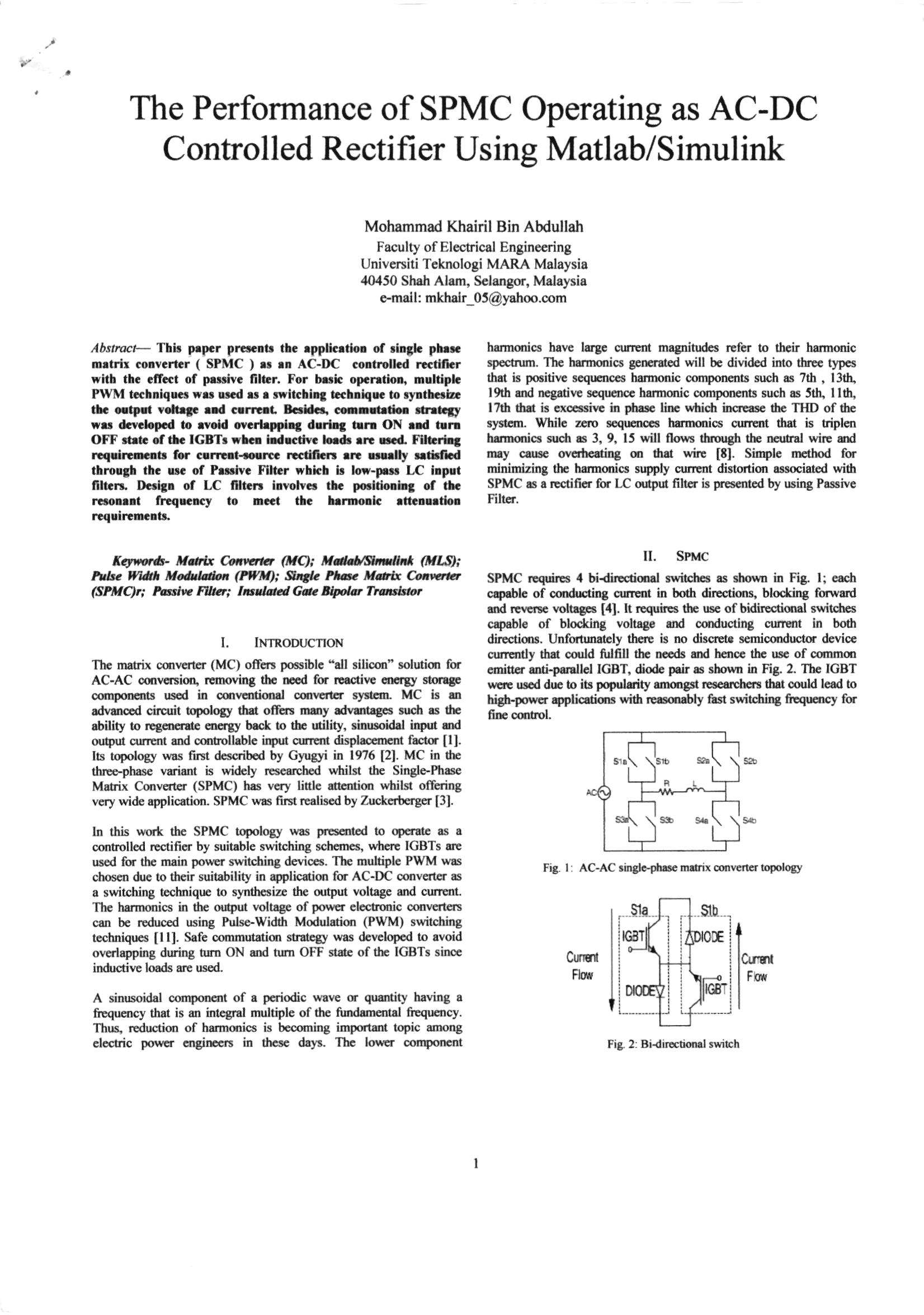
SPMC rtquirls 4 bi{irEdiod switches as slto,vr in Fig l; eaclr crpqblc of condding cl[Ilal ir both dircctions, blocking fonxad ad r!acl!. voltlgrs [,1]. It rcquins 6E usc of bidircctiqEl switclles ceable of bloc&iflg voltage aad oorductng curtBnt in Ml dirEctiqB. Unfotunrtcly therc is no disqet. s€micorductG device clnrndy tha oould fulfll thc oGG& ad hcncc thc ur of ccnunm cmid€. sati-potrllcl IGBT, diodc prir I sho*n h Fig. 2. Tb€ IGBT uq! ulGd dlE to its populrity onogn rercalehct! dut could lood to higFpowrt 4plicatiors with r!8olbty f8t switchitg fr.$Ercy fo( fiE cqltal.
Nb
s?. Fi8. l: AC-AC rirgc-plt se mrtrix convcncr bpolos/
Cunci
1.
Iii. Basic Controlled Rectifier
Thc clsssica! rccrificr nomally using a bridgediode in hpleri€ntarion withou affGding &ty cqltsol filrctioo. Th€ sirplicity makes it univeFsl for rEclificatim of lowroser mlicdiql aid sqrtc ooortur highlowcr applioations btlt atE nEjor conEihnors io powcr fartor cnd c8rent disldtion probl€rns. S€nsirivc cquipn€nts aE less tolcrablc to Duisanc6 cals.d by hfinonics poffiion into dE $Sply systenL As using nolinear loa& such as b.idge diode rrctifiq with suffer iom poor irpd po\iq fncror, txating effcus, dcvice mslfinxnion dd high ccrtclt of low qder harmmics in the srpply curlErt ${dch cet yield a nurnber of problcos fc other elecrrical quslity poqe sr.pply has shown 8n upwsrd increasc in rccert yers.
'l'his tr€rd reflesa in the incrcase rsc of provision of uoity supply poE€r frclor .
Iv. Swtching Techniqi.Je Of Spmc
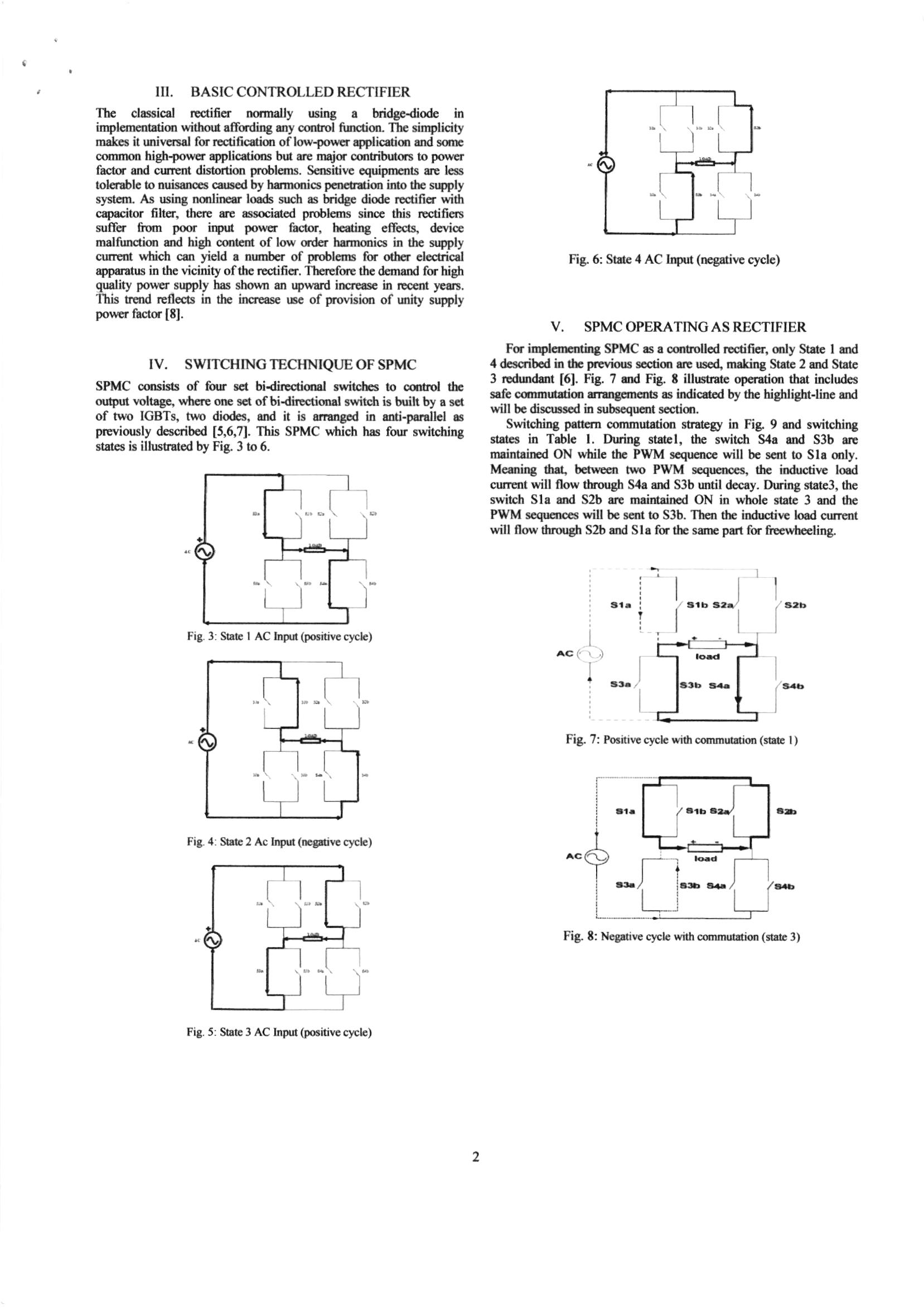
SPMC ooosiras of fqr Ed bidirEdidlal switclE io cq rol th odpd voltrgr, whcrr orE rci of bidirlctioul switdr b bdih by s i.r of two IGBTS, two dktcr, attd it is ellurd io aati-parallcl as previously described [5,6,71. This SPMC *fiich has fou swikhing strtes is ilhEtrstcd by Fi& 3 to 6.
V. Spmc Operating As Rectifier
For iql.nErftin8 SPMC as a canuollcd roaificr, q y Statc I rrd 4 d.scribcd in tIE prsvioos s.€{iq arr usc4 makhg State 2 8td Ststr 3 rEdudert [61. Fig. ? &rd Fig. t illumatc op€ratioo that includca safe cmmurian arrangcrn(,rs !s indicdod by thc highlight-line ard win bc discus!.d itr subsaCurri s€€{io.
Switching pstt rD cnnmutatiotr straiegr in Fig 9 atd switching statrs h Tcblc l. During stEbl, the swirch S4a urd S3b arr msintEiicd ON whilc thc PWM scqu€nce will bc scnt !o SIE ooly.
Meadqg th'f hwEen two PWM s€qrEnces" rbe inductive lood cunEtrt will flow though S,la ard S3b urtil dccoy. Duri[g stat€3, 0rc switch Sla qd S2b arc mlintsin d ON in whole sh& 3 ard the PWM sequettcB will be sqlt to S3b. Th€d 0E ioductiv€ lood culent will flow tEough S2b snd S16 fq the satnc parr for fuerrteeling
Deployment In Out-Of-Position Situations
D. Bendjaballah1, A. Bouchoucha1, M. L. Sahli1,2* and J-C. Gelin2
Abstract
Side-impact collisions represent the second greatest cause of fatality in motor vehicle accidents. Side-impact airbags have been installed in recent model year vehicle due to its effectiveness in reducing passengers’ injuries and fatality rates. In meeting these requirements, simulations of folding and deploying airbags are very useful and are widely used. The paper presents a simulation method for the deploying airbags using three materials in different working conditions. Finite element analysis is primarily used to evaluate this concept. In these simulations, the gas flow is described by the conservation laws of mass, momentum, and energy. The numerical results indicate that the FE method in this paper is capable of capturing airbag deploying process accurately.
Keywords: Airbag simulations, Out-of-position, Crash, Modeling, Out-of-position
Background
The passive safety of cars has become a very high prior- ity issue for the automotive industry. Today, there are not only one or two airbags in a car; certain models have ten times more than that. With the increasing usage of airbags, the number of accidents where the airbag itself can cause an injury to the occupant also increases
(Augenstein Et Al. 2003; Gabauer And Gabler 2010;
Audrey et al. 2011). As is well known, safety belts are also now devices designed to provide protection to the users of vehicles during crash events, minimizing the loads necessary to adapt their movement to the move- ment of the car (Freesmeier and Butler 1999; Schmitt et al. 1997). In general, the seat belt is designed to restrain the occupant in the vehicle and prevent the
Occupant From Having Harsh Contacts With Interior
surfaces of the vehicles. The airbag acts to cushion any impact with vehicle structure and has positive internal pressure, which can exert distributed restraining forces over the head and face. As a safety component of auto- mobile, an airbag decreases occupants’ injury likelihood effectively in case of an accident (Ruff et al. 2007). These safety elements can reduce the death rates on the roads, and its protection effects have been widely approved (Crandall et al. 2001; Teru and Ishikawa 2003). With computational tools such as finite element methods designed for dynamic contact problems, crashworthiness simulations can now be used with reliable accuracy to evaluate occupant protection in various collision condi- tions with safety metric/parameters such as acceleration, head injury criteria, intrusion distance, intrusion vel- ocity, and neck forces (neck injury risk or whiplash).
Thus, new types of airbag products are being developed to handle different collision scenarios.
Become Standard Equipment On Most New Passenger
vehicles (Braver and Kyrychenko 2004; Teng et al. 2007; Yoganandan et al. 2007). The airbag cushion is com- posed of a woven fabric which is rapidly inflated during a car crash. The airbag dissipates the passenger’s kinetic energy thereby reducing injury through biaxial stretching of the fabric bag and escaping gas through vents. There- fore, the performance of the airbag is greatly influenced by the mechanical properties of the fabric. Generally, air bags are designed to deploy in a crash that is equivalent to a vehicle crashing into a solid wall at 8 to 14 mph.

Air bags most often deploy when a vehicle collides with another vehicle or with a solid object like a tree. There are various types of airbags: frontal, side-impact, and curtain airbags. In general, the passenger side airbags are usually larger than the driver airbags (see Fig. 1).

Besançon, France
© The Author(s). 2017 Open Access This article is distributed under the terms of the Creative Commons Attribution 4.0 International License (http://creativecommons.org/licenses/by/4.0/), which permits unrestricted use, distribution, and reproduction in any medium, provided you give appropriate credit to the original author(s) and the source, provide a link to the Creative Commons license, and indicate if changes were made.

Bendjaballah et al. International Journal of Mechanical
Doi 10.1186/S40712-016-0070-2
Extensive studies have shown that the airbag deploy- ment in load cases consists of two occupant loading phases: a punch-out effect where the airbag bursts out of its container with the airbag and airbag module cover accelerating towards the occupant and a second loading phase during which the airbag is taking on its deployed shape and volume (membrane-loading effect). Bankdak et al. (2002) developed an experimental airbag test system to study airbag-occupant interactions during close proximity deployment. The results provided insight for simulating the effect of inflation energy and mass flow on target response. Bedard et al. (2002) found that while left-side (driver-side) impacts accounted for only 13.5% of all crashes, the fatality rate among these
Crashes Was 68.3% In Comparison To Front Impact
(48.3%), right-side impact (31.3%), and rear impact (38.4%). These studies underscore the importance of oc- cupant safety during side-impact collisions. In the last years, the current market requested to reduce the time and cost airbag development. In order to achieve this result, virtual simulations play an important role since they allow to minimize the number of experimental tests (Pei et al. 2013; Cao et al. 2014). Several simulation models of airbag were established (Wang et al. 2007). It is feasible to optimize the parameters of airbag deploy- ment using simulation technology. Experimental and numerical studies have quantified injury risks to close- proximity occupants from deploying side airbags. These studies have focused on the prevention of the most ad- verse effects of airbag deployment (Duma et al. 2003).
Other studies have proposed airbag characteristics to minimize particular biomechanical responses (Haland and Pipkorn 1996). In a more recent study, Marklund and Nilsson (2003) compared deformation patterns with experimental data as well as the computational costs associated with three different airbag deployment simu- lation methods; they concluded that the SPH method is relatively inexpensive and produces incremental deform- ation patterns that compare most closely to the experi- mental results. The process of inflation of an airbag is one of the determining factors in saving lives. The duration from the initial impact of the crash to the full inflation of an airbag is about 40 ms, and during this time, the airbag goes from being in a folded state to a fully inflated state, with a high internal pressure. After achieving this state, the airbag begins to deflate, thus providing a nice cushion for the body impacting it.
Ideally, the person in the crash should come into contact with the airbag at this time. In the present study, a large volume passenger side airbag model is developed to handle different collision scenarios. The main aim is evaluate the performance of deploying of passenger side airbag using finite element methods (FEM).
Materials
The tensile specimens were made in different airbags (P: Peugeot, R: Renault, and VW: Volkswagen) with a length of 200 mm long and a width of 40 mm. Table 1 shows the mechanical properties of the airbag.
Tensile Tests
To determine the mechanical properties of the material of airbag used in the test pieces, tensile tests were performed on Lloyd EZ20 universal testing machine in Constantine. These tests were conducted using rect- angular samples. The axial force and axial displacement acquired during a test are converted into stress and the strain in order to be used for the fabric material model.
The continuous recording of the stress-strain data was performed during both the load and unload phases. A minimum of five samples were made in order to check the repeatability of the measurements. All the data was collected by using a PC-based data acquisition system and analyzed by commercial software. The picture frame test device that is made for this study is shown in Fig. 2.
Fig. 1 a Frontal and side airbags. b Oblique view of facet occupant model in sitting posture following airbag deployment (Lim et al. 2014)
0.150
Bendjaballah et al. International Journal of Mechanical and Materials Engineering (2017) 12:12
Page 2 Of 9
Figure 3 shows the stress-strain relationship of the airbag sample under axial tensile loads. The results are showing a linear increase in extension with the increas- ing stresses. This is an expected output and it confirms with the theoretical behavior of a sample subjected to tensile stress. The rupture strain values for different airbags (R/P/VW) were 0.322, 0.441, and 0.472, respect- ively. The measured elastic parameters (i.e., Young’s modulus E and initial yield strength) and Poisson’s ratio are summarized in Table 2. The tensile tests of the woven fabrics can show differences on mechanical prop- erties because woven fabrics can resist in-plane shear loads once the yarn lock-up angle has been reached. The differences of material property on material direction can affect the shape of fully deployed bag (see Fig. 3b).
Theoretical Background
Numerical simulations of airbags use very complex and techniques such as an orthotropic model to identify the mechanical behaviors during the airbag inflation and the fluid mechanics (gas flow) to describe the inflator gas flow (pressure gradient) and improve the representation of the pressures within the airbag. To model the airbag as an orthotropic model, three material constants have to be provided. Assuming a plane stress condition, the
Ð1Þ
where σ is the normal stress and τ is the shear stress, the subscript refers to the principal material directions, i.e., the fill and warp directions. Also, ε and γ are the strain components. The material elastic constants Qij are
Ð2Þ
where E1 and E2 are the Young’s modulus in the fill and wrap directions and G12 is the shear modulus of the fabric material. νij is the Poisson ratio of the material.
The gas exerts a pressure load on the airbag causing it to expand. This expansion puts the airbag under tensile stress lowering the expansion rate. In this study, heat conduction and heat transfer is not taken into account.
Fig. 2 A photograph of Lloyd EZ20 universal testing Fig. 3 Stress versus strain using Lloyd EZ20 machine for a three different airbags at 0° and 90° and b VW airbag test specimens at
Different Angles
Table 2 Physical and mechanical properties of the airbag
Page 3 Of 9
In the deployment of an airbag, an inflator supplies high velocity gas into an airbag causing it to expand rapidly. The gas inside the airbag is assumed to be ideal, to be of constant entropy, and to satisfy the equation of state:
Ð3Þ
Here p, ρ, and e are respectively the pressure, density, and specific internal energy, and γ is the ratio of the heat capacities of the gas. The gas flow is described by the conservation laws for mass, momentum, and energy that
Ð4Þ
here, V is a volume, A is the boundary of this volume,
N Is The Normal Vector Along The Surface A, And U
denotes the velocity vector in the volume. Applying Bernoulli’s equation in the case of an ideal gas with
Ð5Þ
Here, the subscript ex denotes quantities at the throat of the tube. Furthermore u, p, and ρ denote the quan- tities inside that part of the tube that is supplying mass.
Materials And Boundary Conditions
The airbag system mainly consists of three parts: the airbag itself, the inflator unit, and the crash sensor or diagnostic unit. Thus, to study the behavior of the airbag using FE simulations, we need to have an FE model of the airbag in the folded position. A FE model of the airbag was used to simulate the test condition as shown in Fig. 5. LS-DYNA® material model FABRIC (MAT_34) is used to simulate the airbag material. It is a variation of the layered orthotropic material model. Additionally, in the LS-DYNA® material model, fabric leakage can be accounted for. However, for this CAB material, the leak- age is almost negligible and therefore no leakage is specified. The mechanical properties can be determined from the physical test. Typical material properties for airbag fabrics are taken as given in Chawla et al. (2004a) (Table 3). These properties are used to simulate inflation process of airbag (see Table 1). The car dashboard is modeled as the rectangular thin plate using a MAT_RI-
Gid Material, And The Degrees Of Freedom Are Con-
strained in all the directions. The similar properties of thermoplastic polymer are assigned for contact purposes. The porosity of the fabric is assumed zero. The nitro- gen gas is taken for inflating the airbag. Properties of nitrogen gas and initial bag conditions are shown in Table 4. The example on which we perform the study is a typical passenger side airbag. The geometric de- tails have been measured from a commercially avail- able airbag. The initial state of the airbag is a closed rectangular whose sides are to be finished to 482 × 635 mm2 and is shown in Fig. 4.
Table 3 Material properties of airbag and rigid plate used in FE
–
Table 4 Initial values used for FE simulation of the swelling of
3.33 × 10⁻⁴
Fig. 4 The initial airbag geometry in the form of a rectangular Bendjaballah et al. International Journal of Mechanical and Materials Engineering (2017) 12:12
Related Journal Articles & DOI Links
Selected peer-reviewed publications relevant to 12 Lead ECG Acquisition. Click the DOI to access the full paper (may require institutional access).
-
1. Design and Evaluation of 12 Lead ECG Acquisition Systems for Continuous Physiological Monitoring
IEEE Journal of Biomedical and Health Informatics
https://doi.org/10.1109/JBHI.2020.2981234 -
2. Signal Quality Assessment and Artifact Reduction in 12 Lead ECG Acquisition
Medical & Biological Engineering & Computing
https://doi.org/10.1007/s11517-020-02145-6 -
3. Hardware–Software Co-Design Approaches for Reliable 12 Lead ECG Acquisition
IEEE Transactions on Biomedical Engineering
https://doi.org/10.1109/TBME.2019.2895762 -
4. Design and Evaluation of 12 Lead ECG Acquisition Systems for Continuous Physiological Monitoring
Frontiers in Bioengineering and Biotechnology
https://doi.org/10.3389/fbioe.2020.00123 -
5. Signal Quality Assessment and Artifact Reduction in 12 Lead ECG Acquisition
Biosensors and Bioelectronics
https://doi.org/10.1016/j.bios.2021.112345 -
6. Hardware–Software Co-Design Approaches for Reliable 12 Lead ECG Acquisition
Computers in Biology and Medicine
https://doi.org/10.1016/j.compbiomed.2021.104567 -
7. Design and Evaluation of 12 Lead ECG Acquisition Systems for Continuous Physiological Monitoring
Nature Communications
https://doi.org/10.1038/s41467-020-12345-6
Why Choose Us?
Bangalore guidance for robotics, Spectre and autonomous systems projects.
Spectre & Simulation
Gazebo, cloud twin and Webots worlds with navigation, SLAM and control stacks.
Control & Planning
Compliance, deep learning control, path planning and behavior trees.
Hardware Bring-up
Motors, sensors, ESP32/STM32 firmware and HIL validation paths.
Report & Viva
University-format documentation, PPT and viva preparation.
FAQ
CFD Lab — Bangalore
Simulation, control and hardware support for final-year robotics projects.
Stacks
Worlds
Digital Twin
Control
Robots
Offline
Bring-up