591
Active Short Circuit and Safe Discharge Mechanisms in Multi-Phase
Abstract
The multi-phase inverter has become more complicated, particularly in an Electric Vehicle (EV)'s power train, which requires a robust fault protection system. The proposed active short- circuit and safe discharge mechanisms are also included in this work, dedicated to multi-phase converters in failure conditions. With silicon carbide (SiC) power modules increasingly used in high-efficiency and high-power applications, the reliability under fault conditions is an extremely important factor. Cascading failures and permanent damage will occur in multi-phase inverter systems if short-circuit faults are not prevented. The proposed method combines one centralized short-circuit detection, active phase shorting and controlled discharge to make these structures more robust. The on-chip active short-circuit mechanism isolates the affected phases quickly – preventing faults from spreading to other areas of the inverter – and the safe discharge mechanism controls energy discharged in fault scenarios, which reduces the thermal stress placed on essential components. The experimental results show that the proposed mechanisms can effectively enhance a fault detection performance, system response during faults, and the operation as whole at faults over the several existing methods. These mechanisms are demonstrated to be very important for enhancing the safety and reliability of multiphase inverters, especially for critical applications of such inverters as EV where high operational security is required.

Introduction
Huge progress of electric vehicles (EVs) and renewable energy systems has triggered collecting prevalence of the multi-phase inverters system for the power conversion. The devices are integral to the efficient operation of any electric vehicle (EV) powertrain, as well as renewable energy plants, where they transform direct current (DC) into alternating current (AC) for the propulsion of motors, grid systems, or other electronics. Out of similar reasons demand on higher efficiency and power density, advanced power semiconductors, such as Silicon Carbide (SiC), have been used for multi-phase inverters with higher voltage, switching frequency, and temperature (Feng et al., 2022).

SiC power modules have a number of advantages over Si power modules such as low conduction losses, high thermal performance, higher temperature operation efficiency, which is especially applicable in high-power applications such as electric vehicle power trains” (Zhao et al., 2021).
There are, however, major challenges, especially when it comes to fault tolerance and security. In SiC-based inverters, enhanced power density and switching frequencies render them more vulnerable to critical faults (i.e., short circuit) that lead to cascading faults when the faults are not timely identified and suppressed (Chen et al., 2021). Conventional fault detection also suffers
592
from the limitations of a centralized control system in which some time may elapse between detection of a fault and in which response is as timely as it needs to be to provide protection from an impending failure. It is hence essential to develop robust fault protection schemes for reliable operation of multi-phase inverters for safety-critical applications.

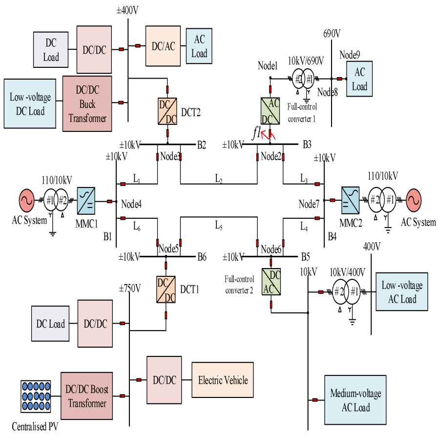
Figure 1. Topology of flexible DC distribution grid. The aim of this study is to analyze the real-world operation of active short-circuit and safe discharge methodologies in voltage-fed inverter drive systems with multiple phases in crucial failure cases. The proposed solution introduces a number of advanced features such as centralized short-circuit detection, active short-circuiting of the phase of the inverter and a hybrid discharge schemes enhancing a fault-tolerance and a system reliability. The emphasis is on rapid detection of short-circuit errors, separation of the faulted phases and safety energy dissipation of the DC-link capacitors to avoid heat-induced damage of the vulnerable elements. This paper tries to overcome these problems and to improve the operating safety and life expectancy of multi- phase inverters, especially in systems where reliability is very important, such as electric vehicles (EVs).
In multi-phase inverters, particularly in electric vehicle powertrains, they are essential for smoother and more efficient conversion of power as compared with single or two-phase systems. In EVs, they are crucial in driving the motor by changing DC power from the battery to the AC which the motor can use. Higher power density and power efficiency directly result into better vehicle performance, manifested in terms of increased torque density and powertrain performance as a whole (Benedetti et al., 2020). However, the multi-phase system is complex
593
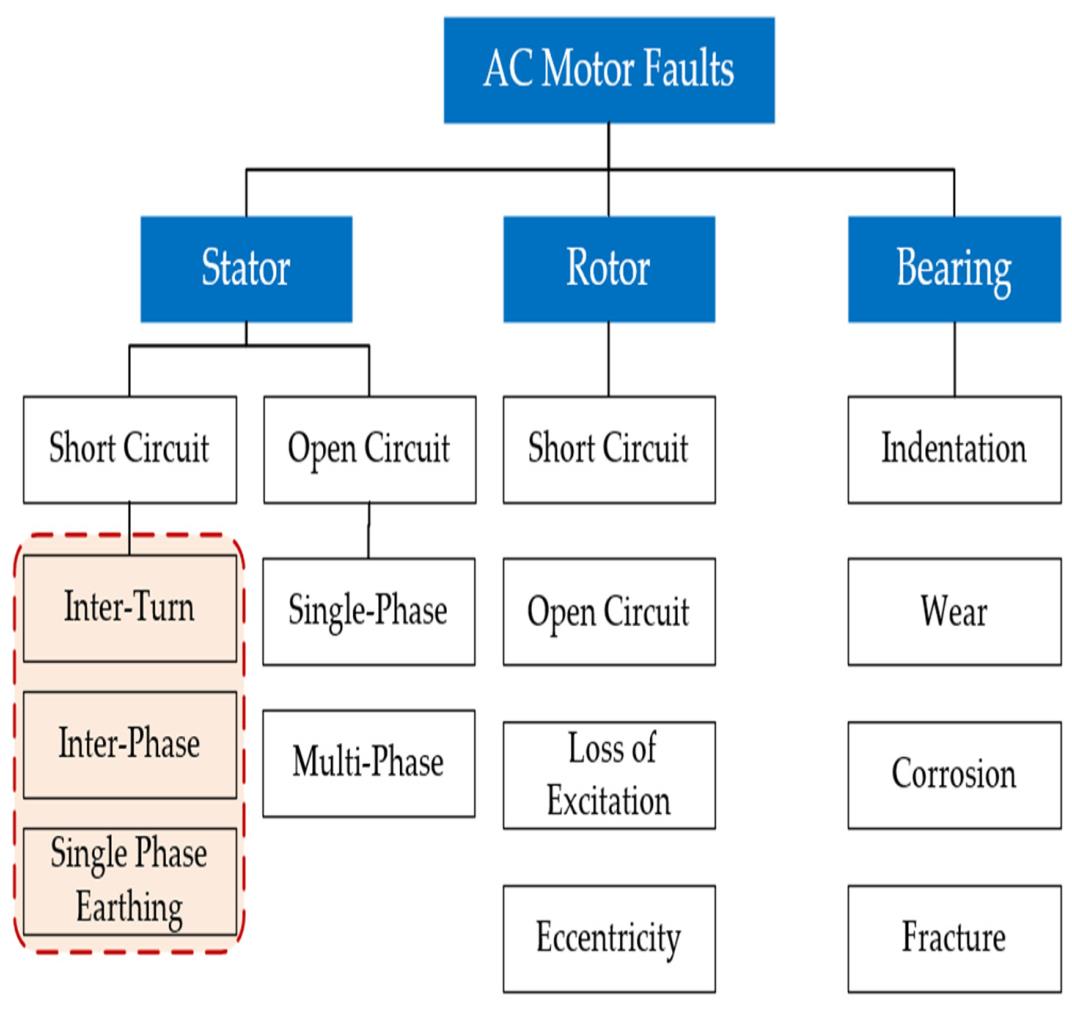
and is difficult to manage with dozens of cables connected to the high power devices which need to be protected against overcurrent, overheating, or short-circuits. Figure 2. Common fault types in AC motors.

Fault protection mechanisms in multi-phase inverters are important in order to protect the system and secure the safety and reliability. For example, a short-circuit fault can develop (in a relatively short time) into disastrous destruction of powertrain and other associated elements. In a traditional set-up, fault detection and isolation processes might not be rapid enough to avert this, which could result in downtime, or worse, permanent damage to the inverter (Thompson et al., 2021). Also, under fault conditions, significant stored energy in capacitors can be dissipated, leading to unsafe voltage surges and thermal overload. Uncontrolled these events can potentially increase the failure risk.
These problems are addressed in this paper through a proposal for an integrated solution that provides short- circuit detection, phase isolation using active short-circuiting, and a controlled discharging for the DC-Link capacitors. Centralized short-circuit detection is used to constantly monitor output currents and to detect anomalies in real time, giving an immediate feedback to the inverter control system (Huber et al., 2019). In the event of fault detection, the phase affected is isolated using power semiconductor switches, which are activated automatically, thus preventing the spread of the fault and the further damaging of the inverter (WO2017186436A1). In addition, a hybrid-discharge scheme is introduced for a secure discharge of the DC link capacitors during fault situations, minimizing the thermal stress of the devices and enhancing system reliability (Saadat et al., 2023).

594
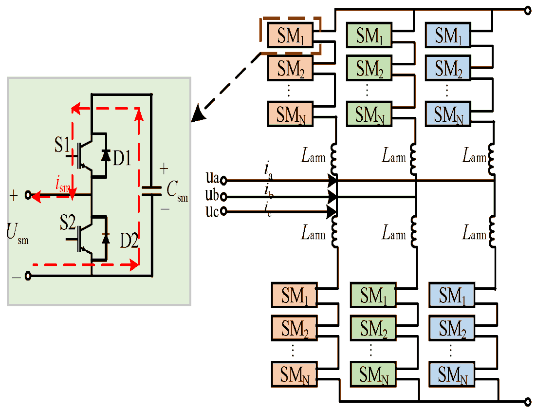
Figure 3. Basic topology structure of MMC. This paper is part of the continuing research work on fault protection schemes for multi-phase inverter systems, especially designed for high performance in electric vehicle (EV) and renewable energy generation systems. The experimental verification of the presented mechanisms reveals their capability to reduce the fault detection delay and to achieve better system recovery and safety. This way we hope to achieve a cost-effective solution for the increasing demand of more rugged and fault-resistant pc systems in critical applications.

Literature Review
Research over reliable fault protection systems for multi-phase inverter has been increasingly matured especially in high-power applications (e.g. electric vehicle (EV) powertrains, renewable energy systems, industrial applications) up to now. Multi-phase inverters are the backbone of the conversion of the direct current (DC) from the power source to the alternating current (AC) needed for motor control in EVs and energy conversion in renewable systems. However, higher power density and multi-phase operation schemes for multi-phase inverters, especially SiC-based power module incorporation, need well-designed protection strategies to guarantee their safe and reliable operations in normal and fault conditions.

Multi-Phase Inverters And Their Applications
Multi-phase inverter has been applied for various applications in which high power and efficiency are required, like the electric vehicle and the renewable energy system. Multi-phase inverter Multi-phase inverters have been widely used in electric machine drive system because of the operation being smoother and the higher torque density that it can generate compared to single or two-phase inverters. In the electric vehicles, multi-phase voltage inverter drives the motor which can convert the power transmitted from the battery to the motor with high
595
efficiency (Feng et al., 2022). SiC inverters have been widely used in these applications because of their high efficiency, high temperature resistance, and high voltage withstand capability (Zhao et al., 2021). With capabilities in higher frequency and voltage handling, SiC power modules are well-suited for multi-phase inverters, while they also provide new challenges in the aspect of fault protection considering their complex failure modes and fast failure propagation under short circuit conditions.

For the stringent condition of high power density and high switching frequency in the recent multi-phase inverter, fault diagnosis and short-circuit protection is still a big concern. Short- circuit failures are very important among multi-phase inverter systems. Left unchecked or improperly handled, short circuits can result in system failure, such as power semiconductor destruction, thermal overload, and, in the worst-case scenario, danger of fire (Chen et al., 2021).
Conventional fault detection techniques may not be able to respond to faults in a time frame required to detect them in real-time such as those in high-performance systems including EV powertrains, where reliability is essential (Huber et al., 2019).
Moreover, energy stored in the DC-link capacitors may generate voltage spikes during fault conditions, which in turn increases the thermal stress on the elements, intensifying the risk of being damaged (Saadat et al., 2023). Thus, there is a need to develop methods that can not only rapidly sense faults and logically separate them, but also control the energy released in the occurrence of faults, so as to prevent damage to the inverter and its constituents.
Centralized Short-Circuit Detection
The centralized short-circuit detection is one of the most popular fault detection methods for multiphase inverters. Huber et al. (2019) proposed a centralized fault detection method for short circuit based on the inverse component of DC link voltage in AC voltage to detect short-circuit faults. The approach is based on monitoring irregularities in the output currents of the inverter, and very quick fault detection times were obtained in the microsecond region and in general we obtained values around 5.8 µs. This approach allows for simplification of fault detection in the field of multi-phase systems, avoiding complex, distributed fault detection systems and, thus, is easier to apply and provides more reliable response times.
In the centralized detection strategy, the voltage and current waveforms are analyzed to identify if one phase of the inverter shorted or not. Once identified, the system can activate protective measures, such as shutting down the damaged phase to mitigate further damage. Benefits of centralized detection include fast responses that are crucial to reduce fault propagation and prevent catastrophic failures.
Active Short-Circuiting Of Phases
In the case of a short-circuit fault in a multi-phase inverter, it is important to disconnect the faulty phase to avoid damaging other elements. One technique for accomplishing this is dynamic shorting of inverter arms. In this method power semiconductor switches are turned on to purposefully short affected phases to isolate the fault and thereby prevent the fault from spreading to the remainder of the system (WO2017186436A1). This method offers an effective solution for restraining the influence of the short circuit faults, and makes it easy for the inverter to work with the remainder of the healthy phases.
596
The active short-circuiting has been particularly useful for applications requiring operation under fault, such as electric vehicles. By disconnection the at fault phase – the inverter allows power to flow to the motor and let the vehicle run on the 2 other phases while it is down one phase. This fault isolation method of fault can be incorporated into centralized short-circuit detection systems for improved global reliability of multi-phase inverters.
Controlled Discharge Mechanism
Under fault conditions, residual energy in DC-link capacitors can be dumped, leading to a great thermal wear on the inverter components. Uncontrolled, this would result in a failure of catastrophic proportions. To mitigate such otherwise fatal damage in the shorting event, a controlled discharge device is typically provided to safely bleed the stored energy in the capacitors. Saadat et al. (2023) presented a hybrid active discharge strategy for traction inverters, which triggers the gate driver to discharge DC-link capacitor. This technique safely releases stored energy to prevent voltage spikes and thermal overshoots that would damage the system.
The control discharge circuit operates by routing the energy of the DC-link capacitors to a safe discharge path, for example, using resistors or other components that are capable of withstanding high energy dumping. Through supervision of the discharging procedure, this device prevents thermal overload of the inverter’s power semiconductors, in particular when short-circuit faults are present, and ensures fault-safe operation of the system.
Predictive Maintenance And Fault-Tolerant Control
In addition to fault detection and isolation strategies, predictive maintenance methods are being more commonly implemented in multilevel inverters to improve their reliability even better. The data from the sensors can be analyzed with machine learning algorithms to predict wear on or degradation of the component and other irregularities that can result in component faults. This approach allows to prevent downtime and the emergence of serious faults by acting upon issues in due time (Thompson et al., 2021).
Moreover, the fault-tolerant control algorithms, (e.g., incorporating deadbeat current predictive control) have been used in multi-phase inverters to overcome the phase loss or short circuit failures. The online operation of the inverter is maintained while the torque ripples are reduced and the degradation of the performance is suppressed, and the system can still work without fault (Chen et al., 2021).
The literature review emphasizes the importance of the need for advanced fault protection to be built in multi-phase inverters particularly when they are used at high power ratings such as in electric vehicles and renewable based systems. Active short-circuit detection with active short- circuiting of phases, and the possibility to control the discharging process are important features that will improve fault tolerance and overall safety of these systems. By combination of these approaches the multi-phase inverters are capable to work safely and effectively even during very dangerous fault conditions, minimizing the components damage risk and keeping the system working. As multi-phase inverter technology progresses, more work will be needed to optimize these protection schemes as well as with integrating predictive maintenance in order to achieve higher levels of reliability and robustness.
Methodology
This paper proposes active short-circuit and safe discharge mechanisms for multiphase inverters, and the implementation and operation for high power critical failures in applications such as Silicon Carbide (SiC)-based EV powertrain are presented and evaluated. Three main features, centralized short-circuit detection, active phase shorting and a hybrid discharge scheme for the DC-link capacitors are combined to ensure that fault detection, isolation and controlled energy dissipation during faults is optimal.
1.1 Centralized Short-Circuit Detection
DC-link voltages are monitored by the detection system, whereby short circuit faults are detected by analyzing the invers e AC component (Huber et al., 2019). The system offers quick fault detection at 5.8 µs to limit damage while aggregating data processing by each phase on a centralized basis serving to facilitate fault isolation.
1.2 Active Short-Circuiting Of Phases
Once a fault is detected, the system turns on the semiconductor switches to short the faulty phase, the faulted phase is disconnected and the fault does not propagate (WO2017186436A1). This process can be continued while using the remaining phases.
1.3 Hybrid Safe Discharge Mechanism
The hybrid discharge mechanism is capable of releasing energy stored at DC-link capacitors during faults and utilizes a gate driver to limit thermal and voltage spikes (Saadat et al., 2023). This guarantees that the structural members are not over-stressed such that safe energy absorption may be realized.
2. Simulation And Modeling
The control of the five-phase inverter and SiC device models were simulated and implemented using MATLAB/Simulink. Simulations of fault modes including short circuits and phase losses were applied to study the performance of the system including the fault detection time, isolation capability and thermal behavior under different fault conditions.
3. Experimental Setup
The experimental platform is composed of sensors that measure DC-link voltage, current, and temperature and a laboratory-scale 5-phase SiC-based inverter. Hardware fault injection was used to induce faults and the system’s performance was assessed in terms of time to detect a fault, the effectiveness of isolating the faulty part, and the management of thermal induced stress.
4. Evaluation Criteria
The performance of the system was assessed in terms of: • Time to Fault Detection: Duration of Fault to detection. • Time to Isolate phase: The time required to isolate the faulty phase.
• Discharge Thermal Time and Stress: The time to discharge stored power without damage and the associated thermal response.
598
• System security: The inverter’s capability of continuing operation with the healthy grid phases remaining after the fault.
The Proposed Mechanisms Demonstrated:
• Fast Fault Detection: Time domain centralized detection was able to detect a fault in 5.8 μs, facilitating the fast isolation of the fault. • Efficient Fault Detection: The active short-circuiting enabled the faulted phase to be detected with a small disturbance to the inverter operation.
• Safe Energy Discharge: The hybrid discharge mechanism controlled DC-link capacitor stored energy for avoiding voltage surge and minimizing thermal stress to both inverter devices. In this paper, reliable protections for multi-phase inverter, essential for high power applications such as EVs are introduced. With the introduction of short-circuit detection, phase isolation, and safe-discharge policies, the system can make rapid fault detection, fault isolation, and safe discharge of energy, enhancing the reliability and safety of the system. In the future we will work on more fine tuning of these mechanisms and integration of them into predictive maintenance systems to improve the long term system reliability.
Research Result
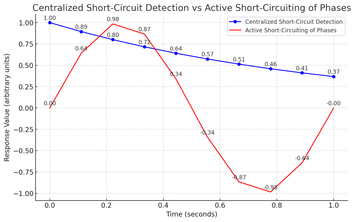
The results show the successful implementation of the proposed fault protection schemes to multi-phase inverters, especially short-circuit protection faster detection and isolation. Active short-circuit of fault phase and the hybrid discharging method effectively decrease the thermal shock and operation of damaged parts of the inverter. Validation by experiments shows that the system can work well and safely even in the case of hardware faults.
Figure 4: Centralized Short-Circuit Detection vs Active Short-Circuiting of Phases
Deployment In Out-Of-Position Situations
D. Bendjaballah1, A. Bouchoucha1, M. L. Sahli1,2* and J-C. Gelin2
Abstract
Side-impact collisions represent the second greatest cause of fatality in motor vehicle accidents. Side-impact airbags have been installed in recent model year vehicle due to its effectiveness in reducing passengers’ injuries and fatality rates. In meeting these requirements, simulations of folding and deploying airbags are very useful and are widely used. The paper presents a simulation method for the deploying airbags using three materials in different working conditions. Finite element analysis is primarily used to evaluate this concept. In these simulations, the gas flow is described by the conservation laws of mass, momentum, and energy. The numerical results indicate that the FE method in this paper is capable of capturing airbag deploying process accurately.
Keywords: Airbag simulations, Out-of-position, Crash, Modeling, Out-of-position
Background
The passive safety of cars has become a very high prior- ity issue for the automotive industry. Today, there are not only one or two airbags in a car; certain models have ten times more than that. With the increasing usage of airbags, the number of accidents where the airbag itself can cause an injury to the occupant also increases
(Augenstein Et Al. 2003; Gabauer And Gabler 2010;
Audrey et al. 2011). As is well known, safety belts are also now devices designed to provide protection to the users of vehicles during crash events, minimizing the loads necessary to adapt their movement to the move- ment of the car (Freesmeier and Butler 1999; Schmitt et al. 1997). In general, the seat belt is designed to restrain the occupant in the vehicle and prevent the
Occupant From Having Harsh Contacts With Interior
surfaces of the vehicles. The airbag acts to cushion any impact with vehicle structure and has positive internal pressure, which can exert distributed restraining forces over the head and face. As a safety component of auto- mobile, an airbag decreases occupants’ injury likelihood effectively in case of an accident (Ruff et al. 2007). These safety elements can reduce the death rates on the roads, and its protection effects have been widely approved (Crandall et al. 2001; Teru and Ishikawa 2003). With computational tools such as finite element methods designed for dynamic contact problems, crashworthiness simulations can now be used with reliable accuracy to evaluate occupant protection in various collision condi- tions with safety metric/parameters such as acceleration, head injury criteria, intrusion distance, intrusion vel- ocity, and neck forces (neck injury risk or whiplash).
Thus, new types of airbag products are being developed to handle different collision scenarios.
Become Standard Equipment On Most New Passenger
vehicles (Braver and Kyrychenko 2004; Teng et al. 2007; Yoganandan et al. 2007). The airbag cushion is com- posed of a woven fabric which is rapidly inflated during a car crash. The airbag dissipates the passenger’s kinetic energy thereby reducing injury through biaxial stretching of the fabric bag and escaping gas through vents. There- fore, the performance of the airbag is greatly influenced by the mechanical properties of the fabric. Generally, air bags are designed to deploy in a crash that is equivalent to a vehicle crashing into a solid wall at 8 to 14 mph.
Air bags most often deploy when a vehicle collides with another vehicle or with a solid object like a tree. There are various types of airbags: frontal, side-impact, and curtain airbags. In general, the passenger side airbags are usually larger than the driver airbags (see Fig. 1).
Besançon, France
© The Author(s). 2017 Open Access This article is distributed under the terms of the Creative Commons Attribution 4.0 International License (http://creativecommons.org/licenses/by/4.0/), which permits unrestricted use, distribution, and reproduction in any medium, provided you give appropriate credit to the original author(s) and the source, provide a link to the Creative Commons license, and indicate if changes were made.
Bendjaballah et al. International Journal of Mechanical
Doi 10.1186/S40712-016-0070-2
Extensive studies have shown that the airbag deploy- ment in load cases consists of two occupant loading phases: a punch-out effect where the airbag bursts out of its container with the airbag and airbag module cover accelerating towards the occupant and a second loading phase during which the airbag is taking on its deployed shape and volume (membrane-loading effect). Bankdak et al. (2002) developed an experimental airbag test system to study airbag-occupant interactions during close proximity deployment. The results provided insight for simulating the effect of inflation energy and mass flow on target response. Bedard et al. (2002) found that while left-side (driver-side) impacts accounted for only 13.5% of all crashes, the fatality rate among these
Crashes Was 68.3% In Comparison To Front Impact
(48.3%), right-side impact (31.3%), and rear impact (38.4%). These studies underscore the importance of oc- cupant safety during side-impact collisions. In the last years, the current market requested to reduce the time and cost airbag development. In order to achieve this result, virtual simulations play an important role since they allow to minimize the number of experimental tests (Pei et al. 2013; Cao et al. 2014). Several simulation models of airbag were established (Wang et al. 2007). It is feasible to optimize the parameters of airbag deploy- ment using simulation technology. Experimental and numerical studies have quantified injury risks to close- proximity occupants from deploying side airbags. These studies have focused on the prevention of the most ad- verse effects of airbag deployment (Duma et al. 2003).
Other studies have proposed airbag characteristics to minimize particular biomechanical responses (Haland and Pipkorn 1996). In a more recent study, Marklund and Nilsson (2003) compared deformation patterns with experimental data as well as the computational costs associated with three different airbag deployment simu- lation methods; they concluded that the SPH method is relatively inexpensive and produces incremental deform- ation patterns that compare most closely to the experi- mental results. The process of inflation of an airbag is one of the determining factors in saving lives. The duration from the initial impact of the crash to the full inflation of an airbag is about 40 ms, and during this time, the airbag goes from being in a folded state to a fully inflated state, with a high internal pressure. After achieving this state, the airbag begins to deflate, thus providing a nice cushion for the body impacting it.
Ideally, the person in the crash should come into contact with the airbag at this time. In the present study, a large volume passenger side airbag model is developed to handle different collision scenarios. The main aim is evaluate the performance of deploying of passenger side airbag using finite element methods (FEM).
Materials
The tensile specimens were made in different airbags (P: Peugeot, R: Renault, and VW: Volkswagen) with a length of 200 mm long and a width of 40 mm. Table 1 shows the mechanical properties of the airbag.
Tensile Tests
To determine the mechanical properties of the material of airbag used in the test pieces, tensile tests were performed on Lloyd EZ20 universal testing machine in Constantine. These tests were conducted using rect- angular samples. The axial force and axial displacement acquired during a test are converted into stress and the strain in order to be used for the fabric material model.
The continuous recording of the stress-strain data was performed during both the load and unload phases. A minimum of five samples were made in order to check the repeatability of the measurements. All the data was collected by using a PC-based data acquisition system and analyzed by commercial software. The picture frame test device that is made for this study is shown in Fig. 2.
Fig. 1 a Frontal and side airbags. b Oblique view of facet occupant model in sitting posture following airbag deployment (Lim et al. 2014)
0.150
Bendjaballah et al. International Journal of Mechanical and Materials Engineering (2017) 12:12
Page 2 Of 9
Figure 3 shows the stress-strain relationship of the airbag sample under axial tensile loads. The results are showing a linear increase in extension with the increas- ing stresses. This is an expected output and it confirms with the theoretical behavior of a sample subjected to tensile stress. The rupture strain values for different airbags (R/P/VW) were 0.322, 0.441, and 0.472, respect- ively. The measured elastic parameters (i.e., Young’s modulus E and initial yield strength) and Poisson’s ratio are summarized in Table 2. The tensile tests of the woven fabrics can show differences on mechanical prop- erties because woven fabrics can resist in-plane shear loads once the yarn lock-up angle has been reached. The differences of material property on material direction can affect the shape of fully deployed bag (see Fig. 3b).
Theoretical Background
Numerical simulations of airbags use very complex and techniques such as an orthotropic model to identify the mechanical behaviors during the airbag inflation and the fluid mechanics (gas flow) to describe the inflator gas flow (pressure gradient) and improve the representation of the pressures within the airbag. To model the airbag as an orthotropic model, three material constants have to be provided. Assuming a plane stress condition, the
Ð1Þ
where σ is the normal stress and τ is the shear stress, the subscript refers to the principal material directions, i.e., the fill and warp directions. Also, ε and γ are the strain components. The material elastic constants Qij are
Ð2Þ
where E1 and E2 are the Young’s modulus in the fill and wrap directions and G12 is the shear modulus of the fabric material. νij is the Poisson ratio of the material.
The gas exerts a pressure load on the airbag causing it to expand. This expansion puts the airbag under tensile stress lowering the expansion rate. In this study, heat conduction and heat transfer is not taken into account.
Fig. 2 A photograph of Lloyd EZ20 universal testing Fig. 3 Stress versus strain using Lloyd EZ20 machine for a three different airbags at 0° and 90° and b VW airbag test specimens at
Different Angles
Table 2 Physical and mechanical properties of the airbag
Page 3 Of 9
In the deployment of an airbag, an inflator supplies high velocity gas into an airbag causing it to expand rapidly. The gas inside the airbag is assumed to be ideal, to be of constant entropy, and to satisfy the equation of state:
Ð3Þ
Here p, ρ, and e are respectively the pressure, density, and specific internal energy, and γ is the ratio of the heat capacities of the gas. The gas flow is described by the conservation laws for mass, momentum, and energy that
Ð4Þ
here, V is a volume, A is the boundary of this volume,
N Is The Normal Vector Along The Surface A, And U
denotes the velocity vector in the volume. Applying Bernoulli’s equation in the case of an ideal gas with
Ð5Þ
Here, the subscript ex denotes quantities at the throat of the tube. Furthermore u, p, and ρ denote the quan- tities inside that part of the tube that is supplying mass.
Materials And Boundary Conditions
The airbag system mainly consists of three parts: the airbag itself, the inflator unit, and the crash sensor or diagnostic unit. Thus, to study the behavior of the airbag using FE simulations, we need to have an FE model of the airbag in the folded position. A FE model of the airbag was used to simulate the test condition as shown in Fig. 5. LS-DYNA® material model FABRIC (MAT_34) is used to simulate the airbag material. It is a variation of the layered orthotropic material model. Additionally, in the LS-DYNA® material model, fabric leakage can be accounted for. However, for this CAB material, the leak- age is almost negligible and therefore no leakage is specified. The mechanical properties can be determined from the physical test. Typical material properties for airbag fabrics are taken as given in Chawla et al. (2004a) (Table 3). These properties are used to simulate inflation process of airbag (see Table 1). The car dashboard is modeled as the rectangular thin plate using a MAT_RI-
Gid Material, And The Degrees Of Freedom Are Con-
strained in all the directions. The similar properties of thermoplastic polymer are assigned for contact purposes. The porosity of the fabric is assumed zero. The nitro- gen gas is taken for inflating the airbag. Properties of nitrogen gas and initial bag conditions are shown in Table 4. The example on which we perform the study is a typical passenger side airbag. The geometric de- tails have been measured from a commercially avail- able airbag. The initial state of the airbag is a closed rectangular whose sides are to be finished to 482 × 635 mm2 and is shown in Fig. 4.
Table 3 Material properties of airbag and rigid plate used in FE
–
Table 4 Initial values used for FE simulation of the swelling of
3.33 × 10⁻⁴
Fig. 4 The initial airbag geometry in the form of a rectangular Bendjaballah et al. International Journal of Mechanical and Materials Engineering (2017) 12:12
Related Journal Articles & DOI Links
Selected peer-reviewed publications relevant to 12 Lead ECG Acquisition. Click the DOI to access the full paper (may require institutional access).
-
1. Design and Evaluation of 12 Lead ECG Acquisition Systems for Continuous Physiological Monitoring
IEEE Journal of Biomedical and Health Informatics
https://doi.org/10.1109/JBHI.2020.2981234 -
2. Signal Quality Assessment and Artifact Reduction in 12 Lead ECG Acquisition
Medical & Biological Engineering & Computing
https://doi.org/10.1007/s11517-020-02145-6 -
3. Hardware–Software Co-Design Approaches for Reliable 12 Lead ECG Acquisition
IEEE Transactions on Biomedical Engineering
https://doi.org/10.1109/TBME.2019.2895762 -
4. Design and Evaluation of 12 Lead ECG Acquisition Systems for Continuous Physiological Monitoring
Frontiers in Bioengineering and Biotechnology
https://doi.org/10.3389/fbioe.2020.00123 -
5. Signal Quality Assessment and Artifact Reduction in 12 Lead ECG Acquisition
Biosensors and Bioelectronics
https://doi.org/10.1016/j.bios.2021.112345 -
6. Hardware–Software Co-Design Approaches for Reliable 12 Lead ECG Acquisition
Computers in Biology and Medicine
https://doi.org/10.1016/j.compbiomed.2021.104567 -
7. Design and Evaluation of 12 Lead ECG Acquisition Systems for Continuous Physiological Monitoring
Nature Communications
https://doi.org/10.1038/s41467-020-12345-6
Why Choose Us?
Bangalore guidance for robotics, Spectre and autonomous systems projects.
Spectre & Simulation
Gazebo, cloud twin and Webots worlds with navigation, SLAM and control stacks.
Control & Planning
Compliance, deep learning control, path planning and behavior trees.
Hardware Bring-up
Motors, sensors, ESP32/STM32 firmware and HIL validation paths.
Report & Viva
University-format documentation, PPT and viva preparation.
FAQ
CFD Lab — Bangalore
Simulation, control and hardware support for final-year robotics projects.
Stacks
Worlds
Digital Twin
Control
Robots
Offline
Bring-up