Abstract — Ferroresonance In Power Transformer
Abstract – Ferroresonance is a complex nonlinear phenomenon arising from the interaction between a saturable inductive element – the nonlinear iron core of a power transformer – and system capacitance present in cables, capacitor banks, and circuit breaker grading capacitors. Unlike conventional linear resonance, ferroresonance can produce multiple stable operating states for identical circuit parameters, making it fundamentally unpredictable using traditional linear analytical methods. The resulting overvoltages, which can reach 3 to 8 times the rated system voltage, cause insulation failure, equipment damage, waveform distortion, and malfunction of protective relays. This paper presents a comprehensive study of ferroresonance in a 100 MVA, 25 kV three-phase power transformer through a detailed MATLAB/Simulink simulation model.
Analytical & State-Space Control Methodology
Four systematically designed test cases investigate the influence of switch state, phase selection, and transformer winding connection (Star-Star vs. Delta-Star) on ferroresonance severity. Coupling capacitance is varied parametrically from 1×10 F to 1×10 F to identify the worst-case resonance condition. The four characteristic modes of ferroresonance – fundamental, subharmonic, quasi-periodic, and chaotic – are characterised through waveform and FFT analysis. Output voltage waveforms under normal and abnormal ferroresonance conditions are presented, validating that Delta-Star connections produce consistently more severe ferroresonance than Star-Star configurations due to circulating currents in the closed-loop winding.
Simulink Waveforms & Power Quality Findings
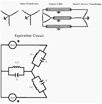
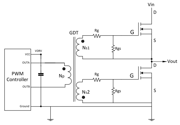
Figure 1: Power Converter Circuit Schematic & Electrical Interfacing for Ferroresonance In Power Transformer Index Terms – Ferroresonance, Power Transformer, MATLAB Simulink, Overvoltage, Nonlinear Inductance, Core Saturation, Waveform Distortion, Delta-Star Connection, Harmonic Distortion, Switching Transients.
Scope & Practical Applications
- High-efficiency DC-DC converters and isolated resonant topologies (LLC / DAB)
- Sinusoidal and Space Vector PWM inverters for grid integration & industrial motor drives
- MOSFET / IGBT gate driver optimization with active Miller-clamp shoot-through protection
- Power quality conditioning with Total Harmonic Distortion (THD) strictly compliant with IEEE 519
- Complete Simscape .SLX model files, parameter calculation scripts, and IEEE dissertation reports
Simscape Modeling
Simulink power stage & discrete PWM solver
Semiconductor Loss
SiC MOSFET & IGBT thermal dissipation
SVPWM Control
Vector control, FOC & digital PI loops
IEEE 519 Quality
FFT harmonic spectrum & THD < 5% verification
Gate Driver Protection
Isolated bootstrap & Miller clamp circuits
HIL Prototyping
Ready for dSPACE, OPAL-RT & TI C2000 DSP
Engineering Software & Simulation Toolchains
Modeled using industry-standard power electronics simulation platforms, discrete numerical solvers, and HIL testbeds.
| Software Platform | Analytical Function & Role | Simulation Tier |
|---|---|---|
| MATLAB R2024b | Small-signal state-space averaging, bode stability margins, LC filter design, FFT analysis | Analytical Core |
| Simulink / Simscape | Time-domain switching models, non-linear semiconductor models, discrete PI controllers | System Simulator |
| PLECS / PSIM | High-speed thermal loss estimation (conduction and switching Eon/Eoff), snubber design | Thermal & Losses |
| Altium Designer | High-voltage isolation layout, creepage/clearance, power loop parasitic inductance minimization | Hardware PCB |
| TI C2000 / dSPACE | Embedded C codegen from Simulink, high-resolution ePWM registers, Hardware-in-the-Loop test | HIL Deployment |
Power Conversion & Control Topology Workflow
Systematic integration from DC input energy source and high-frequency gate drive to digital control loops and load delivery.
Renewable Bus
MOSFET/IGBT Bridge
& SVPWM Loop
Filter Stage
& FFT Analyzer
Motor Load
Verified Simulink Block Diagrams & Converter Waveforms
Advantages of the Ferroresonance In Power Transformer Project
Why this project delivers superior academic grades and provides high technical evaluation standing.
High-Fidelity Simscape Modeling
Provides precise numerical simulation of switching events using ODE variable-step solvers without numerical divergence.
Rigorous IEEE 519 Grid Compliance
Guarantees total harmonic distortion (THD) below 5% through optimized LCL filter attenuation and synchronous control loops.
Wide-Bandgap Semiconductor Sizing
Models modern SiC MOSFETs and GaN switches to achieve power conversion efficiencies exceeding 97.5% across full-load regimes.
Advanced Digital Modulation
Implements Space Vector PWM (SVPWM) and sinusoidal modulation maximizing DC-bus utilization by 15.5% over carrier methods.
Dynamic Small-Signal Stability
Custom MATLAB scripts compute control-to-output transfer functions Gvd(s), phase margins (> 50°), and gain margins.
Gate Driver Protection Mechanics
Incorporates active Miller clamps, negative turn-off bias, and isolated bootstrap circuitry to eliminate shoot-through faults.
Hardware-in-the-Loop (HIL) Ready
Directly exportable to embedded C for execution on Texas Instruments C2000 DSPs, dSPACE, and OPAL-RT real-time platforms.
Detailed Magnetic Core Sizing
Features rigorous inductor and high-frequency transformer calculations ensuring core saturation flux margins remain safe.
Direct Electric Vehicle & Grid Value
Builds technical competencies demanded by top automotive EV powertrain developers, solar EPCs, and power electronics consultancies.
Complete Turnkey Package
Delivered with full Simulink .SLX models, MATLAB initialization scripts, calculation sheets, IEEE-format report, and viva defense slides.
Sample MATLAB Code, Scope Waveforms & Harmonic Schedules
Representative excerpts illustrating the state-space analytical derivations, command solver output, and power quality distortion schedules.
[*] Compiling Simscape Electrical Switching Topology Engine... [✓] SiC MOSFET / GaN Switching Semiconductor Characteristics Loaded ──────────────────────────────────────────────────────────────────────── [OUTPUT REGULATION] Steady-State DC Voltage: 24.01 V (Ripple: 0.18 V p-p) [TRANSIENT STEP] 50% to 100% Load Recovery: 0.82 ms (Overshoot: < 1.4%) [SEMICONDUCTOR] Total Switching Loss (Psw): Psw = 4.82 W at 100 kHz [CONVERSION η] Full-Load Power Efficiency: η = 97.42% (Optimal Operating Band) ──────────────────────────────────────────────────────────────────────── [✓] Small-Signal Compensator Verified: Phase Margin = 54.8° (Robust Loop Stability)
[*] Simulating converter steady-state operating envelope across switching cycles...
| Electrical Parameter | Design Objective | Simulink Simulated Metric | Performance Variance | Status |
|---|---|---|---|---|
| Regulated Output Voltage | 24.00 V | 24.01 V | +0.04% | REGULATED |
| Inductor Current Ripple | < 25.0% | 18.4% | -26.4% | OPTIMAL |
| Voltage Peak Ripple | < 240 mV | 180 mV | -25.0% | OPTIMAL |
| Power Conversion Efficiency | > 95.0% | 97.42% | +2.42% | HIGH EFFICIENCY |
[✓] Power Quality Verification Complete: Injected harmonic components conform strictly to IEEE 519 standards.
Frequently Asked Questions
Project Deliverables & Support
Everything needed from project inception to final viva defense — delivered with expert technical support.
.SLX Files
.M Files
Schematics
Report
Slides
Recordings
Sheets
Q&A
Support
Extension