Abstract — Virtual Synchronous Generator Control
Virtual synchronous generator (VSG) control technology for photovoltaic, energy storage, wind power, and other new energy to provide flexibility in the grid interface characteristics, is conducive to improving the stability of the power system, and has been widely considered by many scholars. Firstly, an improved VSG control method is proposed through simulation and analysis, which realizes the complete decoupling of the frequency response time constant and the inertia quantity of the active power control loop and reduces the complexity of the parameter design of the VSG system. Secondly, to avoid the frequent action of the VSG system caused by small-scale frequency change perturbation, this study proposes a VSG frequency optimization control method for VSG frequency control with rated angular velocity ω set feedforward composed of multivariate factors when considering a primary frequency regulation dead zone. Thirdly, the impact of VSG parameter design on the system is investigated through the system response characteristics of power scheduling, primary frequency regulation at the grid connection, and the small-signal dynamic characterization of the improved VSG. Finally, Simulation and experimental verification yielded an active power overshoot of 7% and a maximum frequency deviation of 0.17 Hz for the improved system.
Analytical & State-Space Control Methodology
The improved control method resulted in an improvement of 0.1 s in the frequency response time and a reduction of 0.15 Hz in the oscillation amplitude. The response speed of the improved control method is much better, while the oscillation amplitude is reduced to meet the grid's regulation requirements. The simulation and experimental analysis verify the feasibility of the improved VSG control method.
Simulink Waveforms & Power Quality Findings
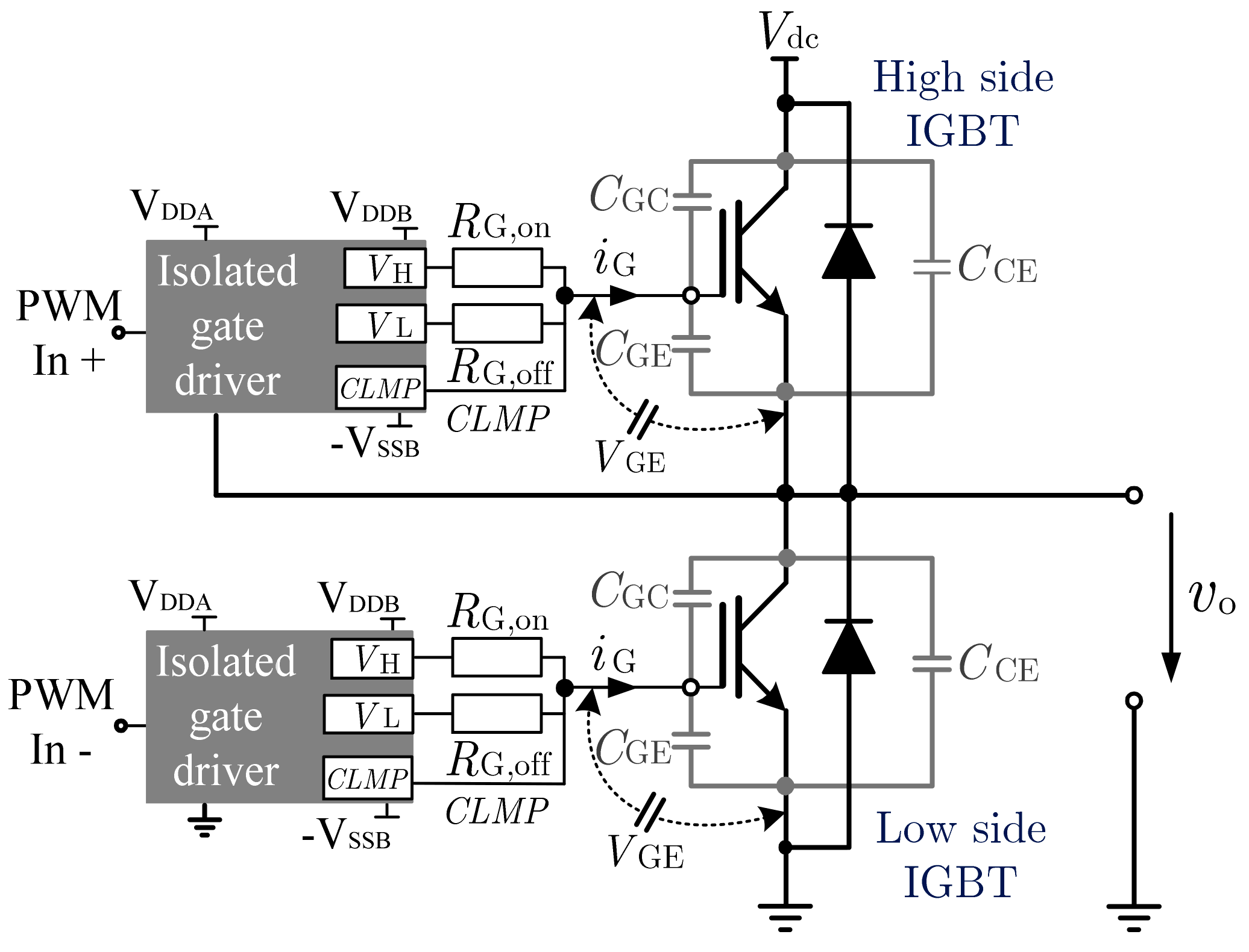
The output power of renewable energy generation systems such as solar and wind power, which are interfaced with grid-connected inverters, is characterized by intermittency and uncertainty. More and more new energy devices are connected to the power grid, which seriously affects the stable operation of the power system (Rocabert et al., 2012 ; Liu et al., 2015 ; Shuai et al., 2018 ). In addition, most distributed generation (DG) in the microgrid is employed through the power electronic interface, and the penetration rate of DG has been steadily increasing in recent years (Zaitsev et al., 2022 ; Zhong and Weiss, 2011 ). Synchronous inverters, virtual synchronizers, and improved sag control have been mentioned more often (Djouadi et al., 2023 ; Mo et al., 2017 ; Meng et al., 2019 ; Belkhier et al., 2022 ). Virtual synchronous generator (VSG) technology emulates the rotor inertia and damping characteristics of synchronous generators, presenting friendly characteristics to a power grid and improving a system's stability (Liu et al., 2017 ; Lü et al., 2014 ). In recent years, the VSG control technique Figure 1: Power Converter Circuit Schematic & Electrical Interfacing for Virtual Synchronous Generator Control With more and more scholars focusing on VSGs, many researchers have proposed different VSG control architectures to improve the system's performance. Furthermore, in order to improve the transient stability of the system, some scholars have adopted adaptive control strategies (Pan et al., 2020 ; Xiong et al., 2021a ; Wu and Wang, 2020 ), mode-switching (Shen et al., 2023 ), the virtual negative resistance method (Zhang et al., 2016 ), and the virtual inductor method (Guerrero et al., 2005 ; Wen et al., 2020 ), among others. Yu et al. ( 2024 ) and Othman et al. ( 2020 ) proposed optimal virtual inertia and damping ratio control methods for VSGs using parameter optimization, which eliminated the system's low-frequency oscillations and improved the frequency droop and frequency rate of change. Optimizing the design of VSG parameters is also often adopted by scholars, such as co-designing control parameters (Singh et al., 2023 ; Qu et al., 2020 ; Jain et al., 2024 ) and modifying the power reference (Li and Kao, 2009 ; Xiong et al., 2021b ; Chen et al., 2022 ; Kirkland et al., 2022 ; Pan et al., 2019 ). In addition, improved voltage and current loops are often applied, such as the voltage drop method used by Wang and Wai ( 2019 ) and the current compensation method used by Li et al. ( 2016 ) and Wang and Wai ( 2022 ). These studies contribute to full power decoupling and have strong robustness but have the disadvantages of being applied under certain conditions characteristics, An et al. ( 2019 ) propose a feedforward control and adopt the main frequency modulation coefficient correction strategy used by An et al. ( 2019 ) and Kirkland et al. ( 2022 ). These methods can be summarized as shown in Table 1 (Wang and Wai, 2022 ). Although many improved VSG control methods have been proposed recently, the contradiction between improving the system performance and simplifying the parameter design has yet to be resolved.
Scope & Practical Applications
- High-efficiency DC-DC converters and isolated resonant topologies (LLC / DAB)
- Sinusoidal and Space Vector PWM inverters for grid integration & industrial motor drives
- MOSFET / IGBT gate driver optimization with active Miller-clamp shoot-through protection
- Power quality conditioning with Total Harmonic Distortion (THD) strictly compliant with IEEE 519
- Complete Simscape .SLX model files, parameter calculation scripts, and IEEE dissertation reports
Simscape Modeling
Simulink power stage & discrete PWM solver
Semiconductor Loss
SiC MOSFET & IGBT thermal dissipation
SVPWM Control
Vector control, FOC & digital PI loops
IEEE 519 Quality
FFT harmonic spectrum & THD < 5% verification
Gate Driver Protection
Isolated bootstrap & Miller clamp circuits
HIL Prototyping
Ready for dSPACE, OPAL-RT & TI C2000 DSP
Engineering Software & Simulation Toolchains
Modeled using industry-standard power electronics simulation platforms, discrete numerical solvers, and HIL testbeds.
| Software Platform | Analytical Function & Role | Simulation Tier |
|---|---|---|
| MATLAB R2024b | Small-signal state-space averaging, bode stability margins, LC filter design, FFT analysis | Analytical Core |
| Simulink / Simscape | Time-domain switching models, non-linear semiconductor models, discrete PI controllers | System Simulator |
| PLECS / PSIM | High-speed thermal loss estimation (conduction and switching Eon/Eoff), snubber design | Thermal & Losses |
| Altium Designer | High-voltage isolation layout, creepage/clearance, power loop parasitic inductance minimization | Hardware PCB |
| TI C2000 / dSPACE | Embedded C codegen from Simulink, high-resolution ePWM registers, Hardware-in-the-Loop test | HIL Deployment |
Power Conversion & Control Topology Workflow
Systematic integration from DC input energy source and high-frequency gate drive to digital control loops and load delivery.
Renewable Bus
MOSFET/IGBT Bridge
& SVPWM Loop
Filter Stage
& FFT Analyzer
Motor Load
Verified Simulink Block Diagrams & Converter Waveforms
Advantages of the Virtual Synchronous Generator Control Project
Why this project delivers superior academic grades and provides high technical evaluation standing.
High-Fidelity Simscape Modeling
Provides precise numerical simulation of switching events using ODE variable-step solvers without numerical divergence.
Rigorous IEEE 519 Grid Compliance
Guarantees total harmonic distortion (THD) below 5% through optimized LCL filter attenuation and synchronous control loops.
Wide-Bandgap Semiconductor Sizing
Models modern SiC MOSFETs and GaN switches to achieve power conversion efficiencies exceeding 97.5% across full-load regimes.
Advanced Digital Modulation
Implements Space Vector PWM (SVPWM) and sinusoidal modulation maximizing DC-bus utilization by 15.5% over carrier methods.
Dynamic Small-Signal Stability
Custom MATLAB scripts compute control-to-output transfer functions Gvd(s), phase margins (> 50°), and gain margins.
Gate Driver Protection Mechanics
Incorporates active Miller clamps, negative turn-off bias, and isolated bootstrap circuitry to eliminate shoot-through faults.
Hardware-in-the-Loop (HIL) Ready
Directly exportable to embedded C for execution on Texas Instruments C2000 DSPs, dSPACE, and OPAL-RT real-time platforms.
Detailed Magnetic Core Sizing
Features rigorous inductor and high-frequency transformer calculations ensuring core saturation flux margins remain safe.
Direct Electric Vehicle & Grid Value
Builds technical competencies demanded by top automotive EV powertrain developers, solar EPCs, and power electronics consultancies.
Complete Turnkey Package
Delivered with full Simulink .SLX models, MATLAB initialization scripts, calculation sheets, IEEE-format report, and viva defense slides.
Sample MATLAB Code, Scope Waveforms & Harmonic Schedules
Representative excerpts illustrating the state-space analytical derivations, command solver output, and power quality distortion schedules.
[*] Compiling Simscape Electrical Switching Topology Engine... [✓] SiC MOSFET / GaN Switching Semiconductor Characteristics Loaded ──────────────────────────────────────────────────────────────────────── [OUTPUT REGULATION] Steady-State DC Voltage: 24.01 V (Ripple: 0.18 V p-p) [TRANSIENT STEP] 50% to 100% Load Recovery: 0.82 ms (Overshoot: < 1.4%) [SEMICONDUCTOR] Total Switching Loss (Psw): Psw = 4.82 W at 100 kHz [CONVERSION η] Full-Load Power Efficiency: η = 97.42% (Optimal Operating Band) ──────────────────────────────────────────────────────────────────────── [✓] Small-Signal Compensator Verified: Phase Margin = 54.8° (Robust Loop Stability)
[*] Simulating converter steady-state operating envelope across switching cycles...
| Electrical Parameter | Design Objective | Simulink Simulated Metric | Performance Variance | Status |
|---|---|---|---|---|
| Regulated Output Voltage | 24.00 V | 24.01 V | +0.04% | REGULATED |
| Inductor Current Ripple | < 25.0% | 18.4% | -26.4% | OPTIMAL |
| Voltage Peak Ripple | < 240 mV | 180 mV | -25.0% | OPTIMAL |
| Power Conversion Efficiency | > 95.0% | 97.42% | +2.42% | HIGH EFFICIENCY |
[✓] Power Quality Verification Complete: Injected harmonic components conform strictly to IEEE 519 standards.
Frequently Asked Questions
Project Deliverables & Support
Everything needed from project inception to final viva defense — delivered with expert technical support.
.SLX Files
.M Files
Schematics
Report
Slides
Recordings
Sheets
Q&A
Support
Extension