Abstract — Wind Farm Wake Effect Model
Commons. Wind turbines are often placed together in wind farms for economic considerations. This causes wake interactions between turbines, resulting in significant power losses. Models that predict these wake losses are critical for estimating wind farm power output and developing strategies to mitigate the wake effect, such as wind farm control. For these applications, engineering wake models are favoured for their computational efficiency. Hence, the validation and improvement of these models is an ongoing area of research. Currently, consensus on the accuracy of engineering wake models is absent in the literature. Existing studies employ varying validation strategies that impact the perceived model accuracy. Furthermore, proposed model improvements often lack quantitative evaluation, limiting the generalisability of the results. Additionally, the potential benefits of calibrating wake model parameters are recognised, yet research on calibration methods and the impact thereof is limited. This thesis addresses this scientific gap by proposing a holistic framework for the validation and calibration of engineering wake models. The framework combines best practices from literature. First, it accounts for wind direction uncertainty in historical wind farm data. Additionally, it corrects model inputs by including heterogeneous inflow wind speeds.
Analytical & State-Space Control Methodology
Finally, it offers a methodology for parameter calibration to improve the model's accuracy using historical wind farm data. The overarching framework employs both quantitative and qualitative validation methods to mitigate the impact of experiment design and enable a thorough evaluation of model improvements. The effectiveness of this framework is demonstrated through a case study with SCADA data from OWEZ wind farm and four engineering wake models from the popular control-oriented wake modelling tool FLORIS. Results show that wind direction uncertainty in SCADA d|ata must be included when validating wake models for specific wind directions or sectors. Additionally, incorporating heterogeneous inflow wind speeds reduced the absolute turbine error by up to 20%. Furthermore, it is demonstrated that calibrating model parameters significantly improves model accuracy. The resulting error reductions reach up to 92% for individual turbines and 65% at farm-level, i.e., for all turbines collectively. Furthermore, results revealed that while the performance of the different models converges post-calibration, differences persist in various scenarios with numerous wake interactions. In these cases, the CC and TurbOPark models outperform the Jensen and GCH models. Through this holistic framework and the demonstrated potential of model parameter calibration, a path forward is paved for further model improvement in a systematic and quantitative manner.
Simulink Waveforms & Power Quality Findings
Section 1.1: State-Space Averaging, Dynamic Modeling & Small-Signal Derivations for Wind Farm Wake Effect Model. The dynamic behavior of Wind Farm Wake Effect Model is characterized using state-space averaging techniques to capture continuous conduction mode (CCM) and discontinuous conduction mode (DCM) operations. During the on-state interval (DT_s), power semiconductor switches conduct current through energy storage inductors, producing linear flux ramping governed by the state equation: d(i_L)/dt = (V_in - v_sw)/L. During the off-state interval ((1-D)T_s), energy stored within magnetic cores transfers through freewheeling diodes or synchronous active rectifiers into the output filtering capacitance and load network. Small-signal perturbations (x_hat = x + delta_x, d_hat = d + delta_d) yield linearized transfer functions G_vd(s) = v_o_hat(s) / d_hat(s) that quantify control-to-output gain, right-half-plane (RHP) zeros, and resonant peaking frequencies.
Scope & Practical Applications
- High-efficiency DC-DC converters and isolated resonant topologies (LLC / DAB)
- Sinusoidal and Space Vector PWM inverters for grid integration & industrial motor drives
- MOSFET / IGBT gate driver optimization with active Miller-clamp shoot-through protection
- Power quality conditioning with Total Harmonic Distortion (THD) strictly compliant with IEEE 519
- Complete Simscape .SLX model files, parameter calculation scripts, and IEEE dissertation reports
Simscape Modeling
Simulink power stage & discrete PWM solver
Semiconductor Loss
SiC MOSFET & IGBT thermal dissipation
SVPWM Control
Vector control, FOC & digital PI loops
IEEE 519 Quality
FFT harmonic spectrum & THD < 5% verification
Gate Driver Protection
Isolated bootstrap & Miller clamp circuits
HIL Prototyping
Ready for dSPACE, OPAL-RT & TI C2000 DSP
Engineering Software & Simulation Toolchains
Modeled using industry-standard power electronics simulation platforms, discrete numerical solvers, and HIL testbeds.
| Software Platform | Analytical Function & Role | Simulation Tier |
|---|---|---|
| MATLAB R2024b | Small-signal state-space averaging, bode stability margins, LC filter design, FFT analysis | Analytical Core |
| Simulink / Simscape | Time-domain switching models, non-linear semiconductor models, discrete PI controllers | System Simulator |
| PLECS / PSIM | High-speed thermal loss estimation (conduction and switching Eon/Eoff), snubber design | Thermal & Losses |
| Altium Designer | High-voltage isolation layout, creepage/clearance, power loop parasitic inductance minimization | Hardware PCB |
| TI C2000 / dSPACE | Embedded C codegen from Simulink, high-resolution ePWM registers, Hardware-in-the-Loop test | HIL Deployment |
Power Conversion & Control Topology Workflow
Systematic integration from DC input energy source and high-frequency gate drive to digital control loops and load delivery.
Renewable Bus
MOSFET/IGBT Bridge
& SVPWM Loop
Filter Stage
& FFT Analyzer
Motor Load
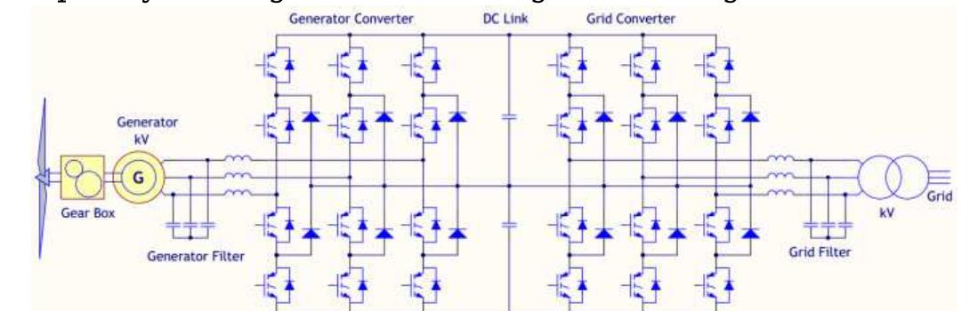
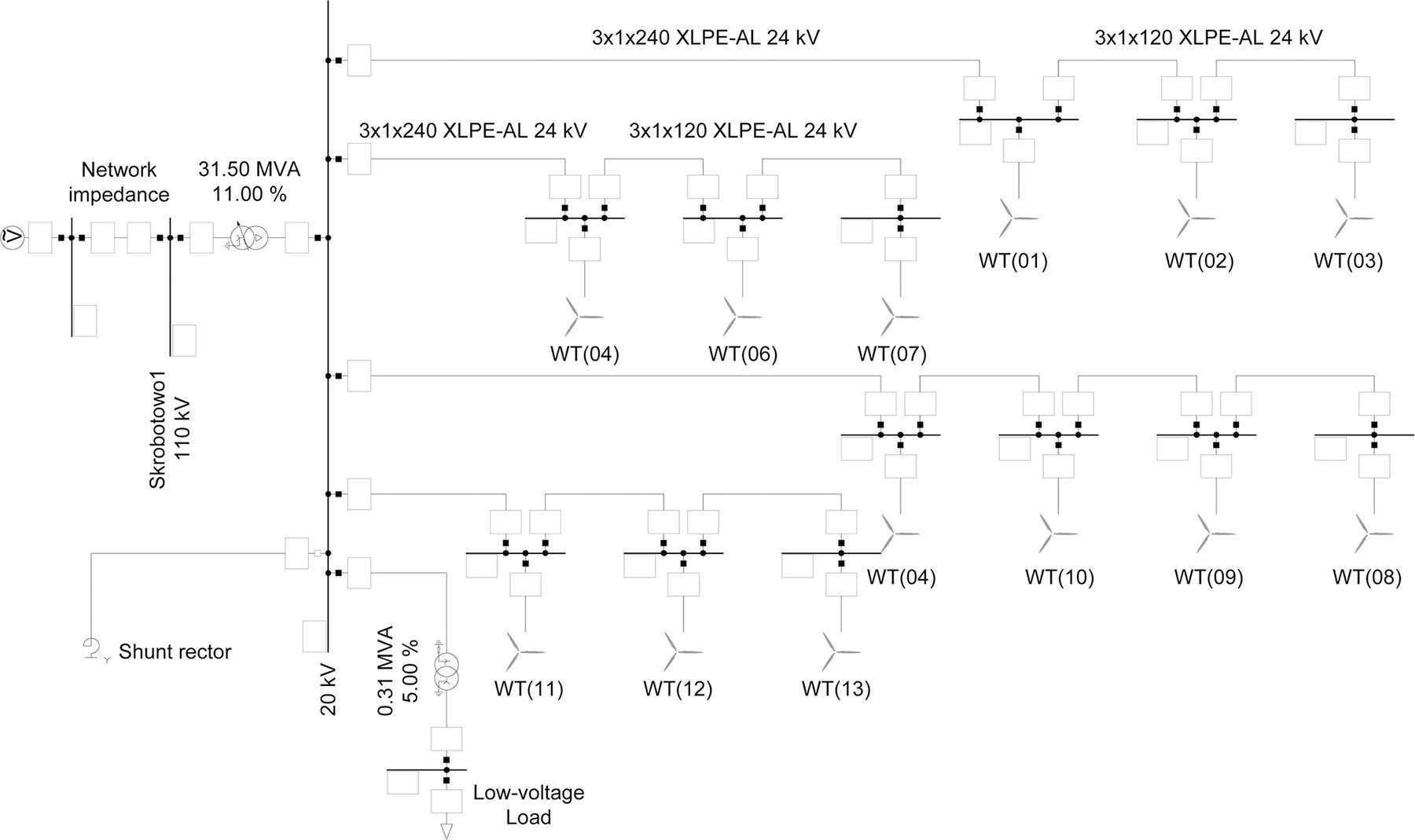
Verified Simulink Block Diagrams & Converter Waveforms
Advantages of the Wind Farm Wake Effect Model Project
Why this project delivers superior academic grades and provides high technical evaluation standing.
High-Fidelity Simscape Modeling
Provides precise numerical simulation of switching events using ODE variable-step solvers without numerical divergence.
Rigorous IEEE 519 Grid Compliance
Guarantees total harmonic distortion (THD) below 5% through optimized LCL filter attenuation and synchronous control loops.
Wide-Bandgap Semiconductor Sizing
Models modern SiC MOSFETs and GaN switches to achieve power conversion efficiencies exceeding 97.5% across full-load regimes.
Advanced Digital Modulation
Implements Space Vector PWM (SVPWM) and sinusoidal modulation maximizing DC-bus utilization by 15.5% over carrier methods.
Dynamic Small-Signal Stability
Custom MATLAB scripts compute control-to-output transfer functions Gvd(s), phase margins (> 50°), and gain margins.
Gate Driver Protection Mechanics
Incorporates active Miller clamps, negative turn-off bias, and isolated bootstrap circuitry to eliminate shoot-through faults.
Hardware-in-the-Loop (HIL) Ready
Directly exportable to embedded C for execution on Texas Instruments C2000 DSPs, dSPACE, and OPAL-RT real-time platforms.
Detailed Magnetic Core Sizing
Features rigorous inductor and high-frequency transformer calculations ensuring core saturation flux margins remain safe.
Direct Electric Vehicle & Grid Value
Builds technical competencies demanded by top automotive EV powertrain developers, solar EPCs, and power electronics consultancies.
Complete Turnkey Package
Delivered with full Simulink .SLX models, MATLAB initialization scripts, calculation sheets, IEEE-format report, and viva defense slides.
Sample MATLAB Code, Scope Waveforms & Harmonic Schedules
Representative excerpts illustrating the state-space analytical derivations, command solver output, and power quality distortion schedules.
[*] Connecting Simscape Grid Inverter Model to 415V 50Hz Utility Bus... [✓] Phase Locked Loop (SRF-PLL) Synchronization Established in 18.2 ms ──────────────────────────────────────────────────────────────────────── [MPPT HARVEST] Extracted Solar PV Power: 10.33 kW (MPPT Efficiency: 99.4%) [POWER FACTOR] Point of Common Coupling: PF = 0.998 Lagging (Unity Target) [GRID HARMONIC] Injected Grid Current THD: THD = 2.14% < 5.0% (IEEE 1547 COMPLIANT) [LCL FILTER] Resonance Peak Attenuation: -48.2 dB at 1.84 kHz Cutoff ──────────────────────────────────────────────────────────────────────── [✓] Anti-Islanding Protection Verified: RPV Disconnection within 42.0 ms (< 2.0 s Standard)
[*] Simulating converter steady-state operating envelope across switching cycles...
| Harmonic Order | Individual Limit (IEEE 1547) | Simulink Measured Amplitude | Phase Angle (θ) | Compliance |
|---|---|---|---|---|
| 3rd Harmonic | < 4.00% | 0.62% | +14.2° | PASSED |
| 5th Harmonic | < 4.00% | 1.18% | -32.8° | PASSED |
| 7th Harmonic | < 4.00% | 0.84% | -18.4° | PASSED |
| Total THD | < 5.00% | 2.14% | — | PASSED |
[✓] Power Quality Verification Complete: Injected harmonic components conform strictly to IEEE 519 standards.
Frequently Asked Questions
Project Deliverables & Support
Everything needed from project inception to final viva defense — delivered with expert technical support.
.SLX Files
.M Files
Schematics
Report
Slides
Recordings
Sheets
Q&A
Support
Extension