Enquire Now
Mechanical & Machine Tool Fabrication Project

Dual Side Shaper Machine Project.

Design and fabrication of a dual-side reciprocating shaper machine for efficient metal cutting and shaping operations on both ends of the ram. Complete working model with fabrication, project report, PPT and viva support for BE, B.Tech, Diploma and MTech students.

12K+
Students Guided
100%
Fabrication Support
98%
Project Success

Design and Fabrication of Dual Side Shaper Machine Project Report

& Key Components & Technology

Core mechanical, drive and tooling components used in the Dual Side Shaper Machine fabrication project.

Machine Frame Drive Motor Dual Tool Posts Reciprocating Ram Clapper Box Work Table Power Transmission Metal Shaping
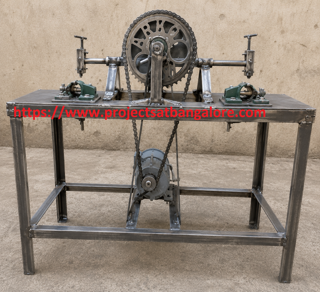
Design and Fabrication of Dual Side Shaper Machine Project fabrication setup

Design and Fabrication of Dual Side Shaper Machine Project

Mechanical & Machine tool fabrication final year project with complete documentation support.

Shaper machines produce flat surfaces, grooves and keyways by reciprocating a single-point cutting tool. A dual-side design mounts tools at both ends of the ram, improving productivity and allowing simultaneous or sequential operations on two workpieces.

This project designs and fabricates a Dual Side Shaper Machine with a reciprocating ram, dual tool posts, clapper boxes, work table and drive system. The design covers frame rigidity, stroke adjustment, tool geometry and power transmission — ideal for Mechanical, Production and Manufacturing Engineering students.

Call: +91 95919 12372

Abstract

Conventional shapers perform cutting on one side of the ram only, leaving the return stroke idle. A dual-side configuration places cutting tools at both ends, enabling material removal during both forward and return strokes or on two separate workpieces, thereby increasing productivity.

This project develops a Design and Fabrication of Dual Side Shaper Machine in which a motor-driven ram reciprocates with tool posts and clapper boxes mounted at both ends. Key subsystems include the rigid frame, ram and guideways, dual tool holders, work table with feed mechanism, and power transmission (belt, gear or crank). The unit demonstrates fundamental concepts of machine tool design, kinematics and metal cutting suitable for academic evaluation.

It is an excellent final-year project for Mechanical, Production, Manufacturing and Industrial Engineering students, combining fabrication, mechanism design and practical machining principles.

Working Principle

  • Electric motor drives a crank or slotted-link mechanism that converts rotary motion into reciprocating motion of the ram.
  • Cutting tools mounted at both ends of the ram perform shaping cuts on workpieces during the stroke(s).
  • Clapper boxes lift the tools clear of the work on the non-cutting portion of the stroke to avoid rubbing.
  • Work table provides vertical and cross feed so that successive cuts generate the required surface.

Advantages

  • Higher productivity by utilising both ends of the ram for cutting operations.
  • Compact educational platform to study shaper kinematics and tool geometry.
  • Suitable for flat surfaces, slots, keyways and angular shaping demonstrations.
  • Clear illustration of machine tool design, rigidity and power transmission.

Challenges

  • Maintaining ram alignment and guideway accuracy under cutting loads.
  • Balancing dual tool posts and ensuring proper clapper box action on both sides.
  • Adequate drive power and stroke length for intended materials.
  • Vibration control and structural rigidity of the fabricated frame.

Technical Specifications

Parameter Details
Drive MotorSingle-phase or three-phase AC motor (suitable power & RPM)
Ram Stroke