Enquire Now
Pneumatic & Mechanical Fabrication Project

Automatic Pneumatic Hammer Machine.

Compressed-air driven reciprocating hammer that delivers controlled impact force for forging, riveting and sheet-metal work. Fully automatic operation with solenoid valves and timer/Arduino control — complete fabrication support for BE, B.Tech, Diploma and MTech students.

12K+
Students Guided
100%
Fabrication Support
98%
Project Success

Automatic Pneumatic Hammer Machine Project Report

& Key Components & Technology

Core pneumatic and mechanical components used in the Automatic Pneumatic Hammer Machine fabrication project.

Pneumatic Cylinder Solenoid Valve Air Compressor Hammer Head Control Timer / Arduino Mild Steel Frame Pressure Regulator Reciprocating Impact
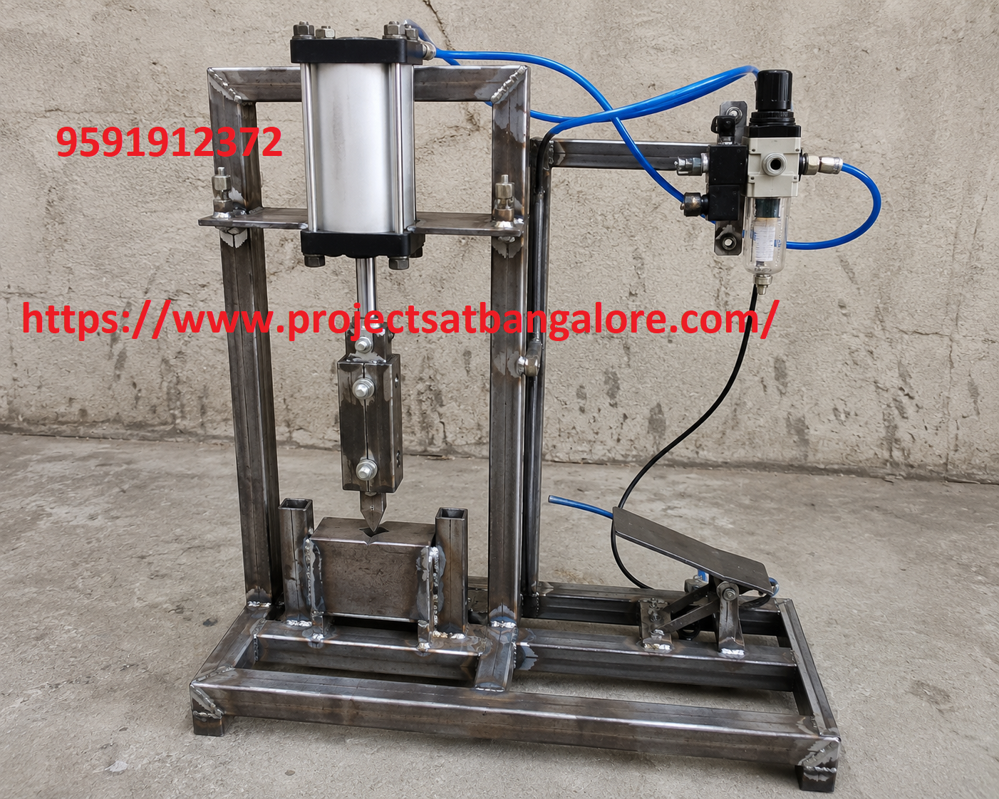
Automatic Pneumatic Hammer Machine Project fabrication setup

Automatic Pneumatic Hammer Machine Project

Pneumatic & Mechanical fabrication final year project with complete documentation support.

Manual hammering is labour-intensive and inconsistent. This project replaces hand-operated hammers with a fully automatic pneumatic system that delivers controlled, high-impact blows at a set frequency.

A double-acting pneumatic cylinder drives the hammer head. Solenoid valves controlled by a timer or Arduino cycle the air supply, producing continuous reciprocating motion. The machine is ideal for light forging, riveting, sheet-metal forming and educational demonstration of industrial pneumatic systems.

Call: +91 95919 12372

Abstract

Pneumatic power is widely used in industry for its cleanliness, safety and high force density. The Automatic Pneumatic Hammer Machine converts compressed air energy into mechanical impact energy through a reciprocating cylinder-driven hammer.

The system consists of a double-acting pneumatic cylinder mounted on a rigid mild-steel frame, a pair of 5/2 solenoid valves, an air compressor with regulator, and an electronic control circuit (timer or Arduino) that alternates the valves to produce continuous up-and-down motion of the hammer head.

It is an excellent final-year project for Mechanical and Mechatronics students to demonstrate pneumatic circuit design, automation and practical fabrication skills.


Working Principle

  • Compressed air from the compressor is regulated and supplied to the solenoid valves.
  • The control circuit energises the valves alternately, directing air to either side of the cylinder.
  • The piston rod extends and retracts, driving the hammer head up and down.
  • Impact force is delivered to the workpiece; stroke rate is adjustable via the timer.

Advantages

  • High impact force with low operator effort and consistent blow rate.
  • Clean, safe and environmentally friendly compared with electric or hydraulic hammers.
  • Simple, robust design using readily available pneumatic components.
  • Stroke frequency and force can be adjusted by pressure and timer settings.

Challenges

  • Proper sealing and alignment of the pneumatic cylinder to avoid air leakage.
  • Vibration isolation of the frame during continuous impact operation.
  • Selection of suitable cylinder bore and pressure for the required impact energy.
  • Safe electrical isolation of the control circuit from the high-pressure air system.

Technical Specifications

Parameter Details
ActuatorDouble-acting pneumatic cylinder (bore 32–50 mm)
Control Valves5/2 solenoid valves (24 V or 12 V)
Air SupplyCompressor / air tank with pressure regulator (4–8 bar)
ControlElectronic timer or Arduino-based sequencing
FrameMild-steel fabricated base and vertical column
Hammer ToolHardened steel head (interchangeable)

What We Provide

ProjectsatBangalore offers complete support for the Automatic Pneumatic Hammer Machine Project including working fabrication, project report, PPT, pneumatic circuit diagram, viva questions, and demonstration guidance for BE, B.Tech, Diploma, and MTech students in Bangalore.

Working Fabrication
Project Report
PPT Presentation
Pneumatic Circuit
Viva Support
Demo Guidance