Enquire Now
Pneumatic & Mechanical Fabrication Project

Design and Fabrication of Pneumatic Bearing Puller.

Compressed-air powered bearing puller that safely and efficiently extracts bearings from shafts and housings. Controlled force, reduced risk of damage and complete fabrication support for BE, B.Tech, Diploma and MTech students.

12K+
Students Guided
100%
Fabrication Support
98%
Project Success

Design and Fabrication of Pneumatic Bearing Puller Project Report

& Key Components & Technology

Core pneumatic and mechanical components used in the Design and Fabrication of Pneumatic Bearing Puller project.

Pneumatic Cylinder Puller Jaws / Arms Solenoid Valve Pressure Regulator Mild Steel Frame Air Compressor Control Switch Safe Extraction
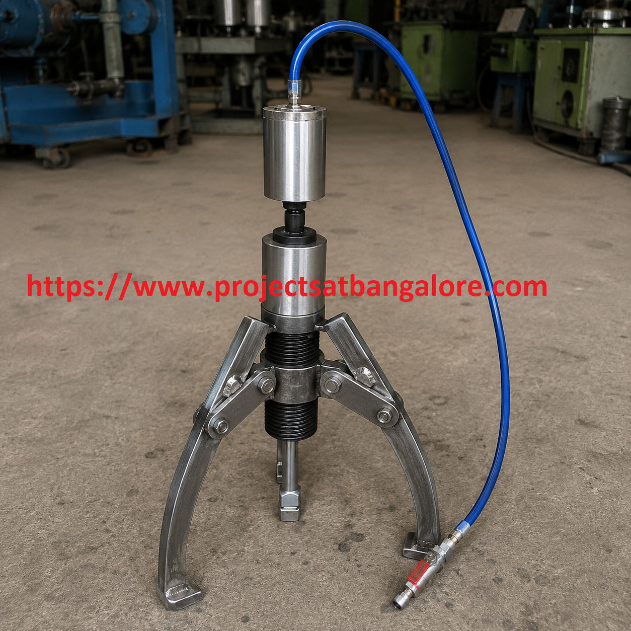
Design and Fabrication of Pneumatic Bearing Puller Project setup

Design and Fabrication of Pneumatic Bearing Puller Project

Pneumatic & Mechanical fabrication final year project with complete documentation support.

Removing bearings from shafts or housings with traditional mechanical pullers can damage components and requires high manual effort. This project develops a pneumatic bearing puller that uses controlled compressed-air force for safe, efficient extraction.

A double-acting pneumatic cylinder actuates adjustable jaws or arms that grip the bearing. Regulated air pressure provides smooth, controllable pulling force, reducing the risk of shaft or housing damage while minimising operator fatigue — ideal for workshop and educational demonstration.

Call: +91 95919 12372

Abstract

Bearing removal is a common maintenance task in automotive, industrial and agricultural machinery. Conventional mechanical pullers rely on screw force and can cause uneven loading or component damage. A pneumatic alternative offers controllable force and reduced physical effort.

This project designs and fabricates a pneumatic bearing puller consisting of a robust mild-steel frame, a double-acting pneumatic cylinder, adjustable gripping jaws, solenoid or manual control valves and a pressure regulator. Compressed air drives the cylinder to pull the bearing smoothly from the shaft or housing.

It is an excellent final-year project for Mechanical and Mechatronics students, combining pneumatic circuit design, structural fabrication and practical workshop application.


Working Principle

  • Adjustable jaws grip the outer race or edge of the bearing to be removed.
  • Compressed air is supplied through a regulator and control valve to the pneumatic cylinder.
  • The cylinder extends or retracts, applying controlled axial force to extract the bearing.
  • Force and speed are adjusted via air pressure for different bearing sizes and fit conditions.

Advantages

  • Controlled, smooth pulling force reduces risk of shaft or housing damage.
  • Significantly lower operator effort compared with manual screw-type pullers.
  • Adjustable jaws accommodate a range of bearing sizes.
  • Clean, reliable pneumatic operation suitable for workshop environments.

Challenges

  • Designing jaws that grip securely without damaging the bearing or shaft.
  • Ensuring structural rigidity of the frame under high pulling loads.
  • Proper sealing and alignment of the pneumatic cylinder.
  • Selecting suitable operating pressure for different bearing interference fits.

Technical Specifications

Parameter Details
ActuatorDouble-acting pneumatic cylinder
ControlManual / solenoid valve with pressure regulator
JawsAdjustable gripping arms (mild steel / hardened tips)
FrameMild-steel fabricated structure
Air SupplyCompressor, typical operating pressure 4–8 bar
ApplicationBearing extraction from shafts and housings

What We Provide

ProjectsatBangalore offers complete support for the Design and Fabrication of Pneumatic Bearing Puller Project including working fabrication, project report, PPT, pneumatic circuit diagram, viva questions, and demonstration guidance for BE, B.Tech, Diploma, and MTech students in Bangalore.

Working Fabrication
Project Report
PPT Presentation
Pneumatic Circuit
Viva Support
Demo Guidance