Enquire Now
Thermal & Mechanical Fabrication Project

Stirling Engine Project.

External combustion heat engine that converts thermal energy into mechanical work through cyclic compression and expansion of a working gas. Complete working model with fabrication, project report, PPT and viva support for BE, B.Tech, Diploma and MTech students.

12K+
Students Guided
100%
Fabrication Support
98%
Project Success

Stirling Engine Project Report

& Key Components & Technology

Core mechanical and thermal components used in the Stirling Engine fabrication project.

Displacer Piston Power Piston Crankshaft Flywheel Regenerator Hot & Cold Ends Heat Source External Combustion
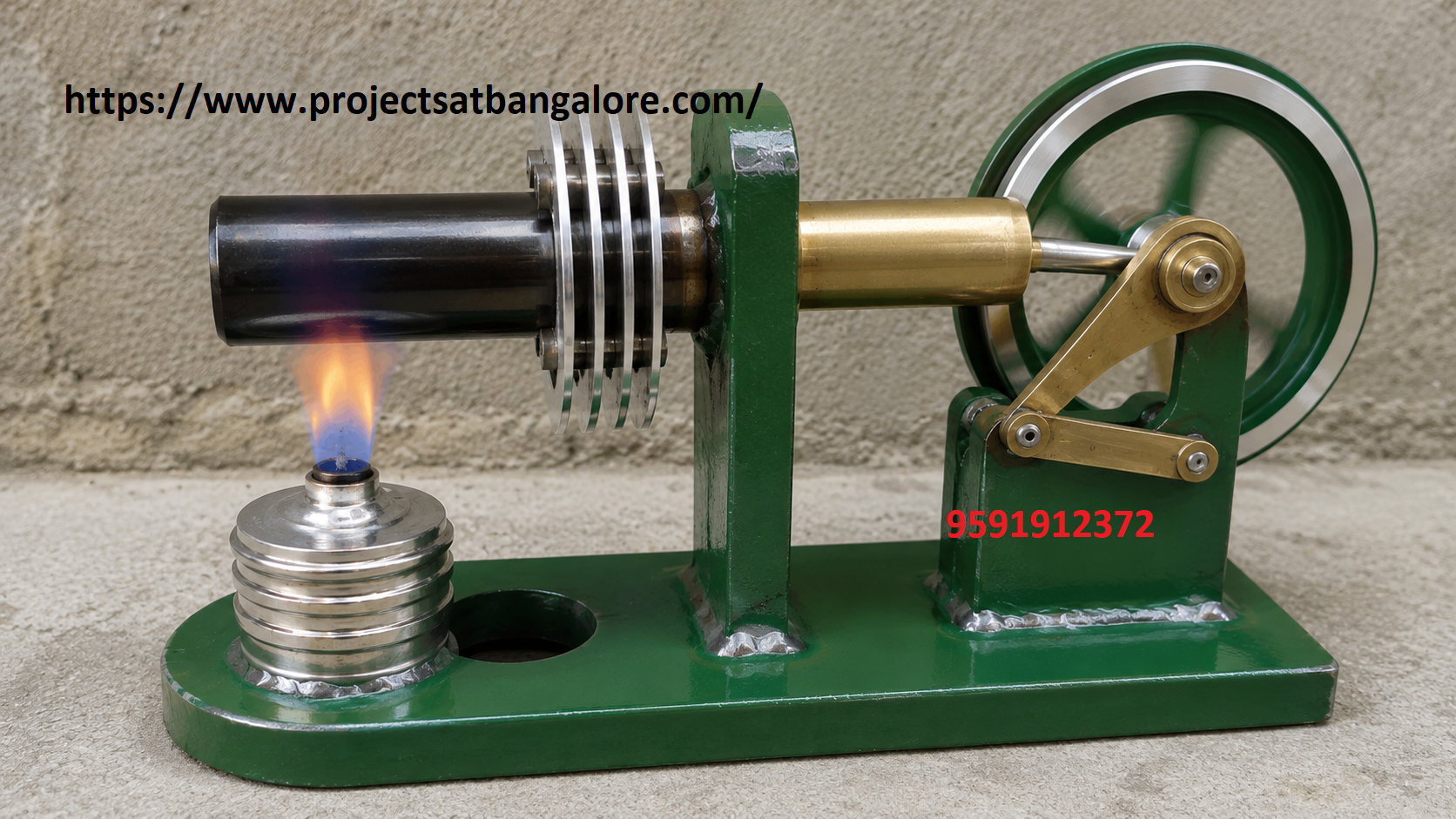
Stirling Engine Project fabrication setup

Stirling Engine Project

Thermal & Mechanical fabrication final year project with complete documentation support.

The Stirling engine is a closed-cycle external combustion engine that converts heat from any external source into mechanical work through the cyclic compression and expansion of a fixed quantity of working gas (usually air).

This project fabricates a working gamma- or beta-type Stirling engine featuring displacer and power pistons, crank mechanism, flywheel and separate hot and cold zones. It demonstrates core thermodynamic principles and can operate on solar heat, waste heat or a simple burner — ideal for Mechanical and Thermal Engineering students.

Call: +91 95919 12372

Abstract

Internal combustion engines dominate modern power generation, yet external combustion engines such as the Stirling engine offer unique advantages: quiet operation, fuel flexibility and potential for high theoretical efficiency. The Stirling cycle involves isothermal compression and expansion with constant-volume heat transfer via a regenerator.

This project designs and fabricates a functional Stirling engine that converts heat energy into continuous rotary motion. Key components include the displacer piston (which shuttles the working gas between hot and cold spaces), power piston (which extracts work), crankshaft, flywheel and heat exchanger surfaces.

It is an outstanding final-year project for Mechanical Engineering students studying thermodynamics, heat engines and renewable energy applications.


Working Principle

  • Heat is applied to the hot end, expanding the working gas and driving the power piston.
  • The displacer moves the gas to the cold end where it contracts.
  • The power piston returns, compressing the cooled gas.
  • The cycle repeats, producing continuous rotary motion at the flywheel.

Advantages

  • Can run on any external heat source (solar, biomass, waste heat, burner).
  • Quiet, smooth operation with low vibration compared to IC engines.
  • Closed cycle — no exhaust gases or internal combustion products.
  • Excellent educational demonstration of thermodynamic cycles.

Challenges

  • Achieving adequate temperature difference between hot and cold ends.
  • Minimizing friction and leakage of the working gas.
  • Proper phasing between displacer and power piston (typically 90°).
  • Material selection for high-temperature components and sealing.

Technical Specifications

Parameter Details
Engine TypeGamma or Beta configuration Stirling engine
Working FluidAir (atmospheric pressure)
PistonsDisplacer + Power piston with crank linkage
FlywheelBalanced flywheel for smooth continuous rotation
Heat SourceSpirit lamp / candle / solar concentrator / electric heater
FrameAluminium / mild steel fabricated base and supports

What We Provide

ProjectsatBangalore offers complete support for the Stirling Engine Project including working fabrication, project report, PPT, thermodynamic analysis, viva questions, and demonstration guidance for BE, B.Tech, Diploma, and MTech students in Bangalore.

Working Fabrication
Project Report
PPT Presentation
Thermodynamic Analysis
Viva Support
Demo Guidance